1
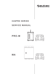
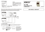
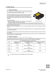
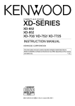
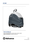
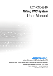
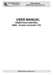
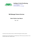
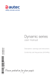
1
CONVENTIONS
Any pieces of text written in bold should be read very carefully.
This symbol highlights extremely important indications and information which, if not observed, can create seriously dangerous situations for people,
equipment or property.
This symbol highlights all important indications and information that deal
with operation.
2
CONFORMITY
The C26 PRO series PRO-M radio remote control is in conformity with the
R&TTE 99/05/EC Directive and its essential requirements.
The radio remote control is also in conformity with the norms given in the EC conformity declaration that is included in this manual.
In Technical Data (see chapter 14) there are the characteristics of safety functions
according with EN 954-1.
It should be remembered that in some countries rules which control
the use and/or possession of a radio remote control must be respected (see the enclosed "Limitations & Authorisations").
Some national limitations may be present for the use of frequencies
which have not yet been harmonised in European countries. Before
using the radio remote control, verify that it works in a frequency
band which is allowed by national radiocommunication laws.
As required by the Machines Directive and relative harmonised standards, all machines must undergo a risk analysis; therefore it is necessary to evaluate, within the limits of this analysis, if the machine can be radio remote controlled.
The machine producer and/or the person who decides upon radio remote control use
and installation is responsible for this analysis.
Autec cannot be held responsible if the risk analysis is not carried out correctly and if the radio remote control is installed on applications that are different from those permitted:
PERMITTED APPLICATIONS:
Hoisting and moving machines installed exclusively on vehicles that
use a battery as electrical power supply source (for example:
hydraulic cranes, concrete pumps . . .)
FORBIDDEN APPLICATIONS
- machines installed in areas where equipment with explosion-proof
characteristics are being used
- AC supplied machines
- machines using a DC supply that does not come from a battery
- machines where risk analysis regarding verification of radio remote control conformity to the application is not possible or has given
a negative or uncertain result.
To guarantee correct radio remote control operation, all current regulations regarding
safety at work and accident prevention should be respected. All current user country
national laws regarding the use of both the machine and the radio remote control
MUST ALWAYS be respected.
Autec cannot be held responsible if the radio remote control is used in unlawful working conditions.
LIPROMU2-01
- 17 -
English
3
RADIO REMOTE CONTROL DESCRIPTION
Industrial radio remote controls are used to
command machines from a distance. Each industrial radio remote control is made up of a
portable transmitting unit, from which the user
can remotely control the machine, and a receiving unit installed on board the machine itself.
The transmitting unit sends a coded message
over radio frequency transmission. This message contains a value called address, which lets
the receiving unit decode only the messages
coming from its own transmitting unit (the one
that has the same address).
This ensures that no interference can activate
any command. If the radio frequency transmission is disturbed, incorrect or interrupted, the
receiving unit autonomously stops the whole
system.
4
Receiving
unit
Transmitting
unit
WARNINGS REGARDING INSTALLATION
Installation must only be carried out by qualified and trained people
and in accordance with installation country rules. Only a correct installation can ensure the necessary level of safety during subsequent radio remote control use.
General
indications Respect the machine operational characteristics when connecting the Radio remote
control. The safety circuits on the radio remote control and/or present on the
machine should not be bypassed (or excluded).
The receiving unit wiring can be configured very easily, therefore it can be installed
without having to modify the machine. Do not modify the machine electric panel
without the machine manufacturer authorisation.
Disconnect the receiving unit by detaching all the electrical connections each time some welding operation is performed on the machine.
Installation
The receiving unit must be placed in a position that favours reception of the
signals issued by the transmitting unit. It should therefore be assembled vertically (antenna upwards). The receiving unit should also be easily accessible to permit
working in safe conditions.
If the receiving unit is covered by metal structures or installed inside metal panels,
use the appropriate extension kit for external antennas.
The antenna must never come into contact with metal parts.
It is forbidden to pierce the receiving unit container. Doing so compromises
the protection degree against external agents (level IP65).
The vehicle creates vibrations, therefore antivibration blocks must always be used to
reduce the effect that these vibrations have on the receiving unit.
The receiving unit must be positioned away from heat sources (exhaust pipes, alternators, radiators, etc.)
Wiring
Most machines are connected to the receiving unit by multiple-pole plugs which let
the radio remote control be disconnected quickly whenever necessary and replaced
by an alternative wired (cabled) control. This connecting technique is advisable even
if the machine is not originally equipped for it.
- 18 -
LIPROMU2-01
The reliability of the installation is largely dependent on the quality of the wiring, and
connections should therefore be made to the highest standards using multi-core or
single-core cables of suitable cross-sectional area for the current to be carried. Cables should also be flame retardant (for futher information refer to EN 60204 - 1).
Cables with anti-oil protection should be used for connections external to the receiving unit.
The receiving unit power supply must pass through an isolation
switch to permit power disconnection during installation, wiring
and/or maintenance operations.
To improve radio remote control operation, connect the receiving
unit immediately downstream of the machine main switch.
It is always advisable to check the supply voltage even under maximum load; in this
way the maximum variations can be verified (the limit values of tolerated deviation
are given both in the Technical Data and on the technical card of the Radio remote
control).
Receiving unit supply voltage fluctuations that exceed the limit values can compromise regular radio remote control operation.
The C26-PRO series radio remote controls are equipped with circuits that protect
against involuntary movements from the actuator rest position (SAFETY function).
This protection is available if the movement commands common of the receiving unit
is in series with the STOP contact and SAFETY contact (which closes when a movement command is transmitted). On the contrary, the selection command common
can not be in series with the SAFETY contact.
Example of
wiring
Proportional
output
setting
Autec supplies the radio remote control with the proportional output values already set depending on type of valves. During installation, these values must be verified and, if necessary, modified
according to how the machine is to user’s working preference (see
chapter 11).
Testing
When installation and wiring have been completed, always do the following:
- make sure that when the radio remote control STOP pushbutton is pressed the machine goes into a situation of safety (through direct action on the general solenoid
valve of the main circuit), the motor possibly switches off and, if present, the
main line contactor opens to remove voltage.
- make sure that the manoeuvres carried out by the machine and which have been
commanded by the transmitting unit correspond exactly (this correspondence is given in the technical data sheet)
- check safety circuit operation (a simple way of doing this is to remove fuse F3,
housed on the main board of the Receiving Unit. Make sure that in these conditions
no movement command can be carried out, then insert the F3 fuse again and check
correct operation)
The installer must also compile and/or verify the two copies of the technical
data sheet, where the wiring layout between the receiving unit and the machine is given. The first copy of the technical card is inside the receiving unit,
the second is annexed to the user's manual. The installer must put the date
of installation, sign and stamp both copies.
LIPROMU2-01
- 19 -
English
5
WARNINGS REGARDING USE
The radio remote control can only be used by operators who:
- have read and understood this manual,
- are qualified and trained,
- know the "radio remote control + machine" system well.
Autec cannot be held responsible if the radio remote control is installed on applications other than those permitted and if used in irregular working conditions.
Each time the transmitting unit is powered, make sure that the
STOP pushbutton operates correctly and that, when pressed, machine movement is interrupted instantly.
If it doesn’t happen, do not use the radio remote control.
The operator should always ensure that both units are whole and
that the gaskets, bellows and hoods of the actuators (joysticks, selectors, pushbutton) are whole. If not, the radio remote control mustn’t be used before being repaired.
To work efficiently and to prevent possible emergency situations, it
is necessary to select a position from where it is possible to:
- remain inside the typical working range of the radio remote control
(see chapter 14)
- visibly follow the machine, its movements and its load at all times.
During
operation
The operator must:
- switch off the transmitting unit each time work is stopped
- NEVER leave the transmitting unit unattended with the starting
key inserted
- avoid working if the battery is almost flat.
The operator should never switch on or activate the transmitting
unit unless ready to start working. A radio link can be created even
outside the active range or within enclosed places, making the radio
remote controlled machine carry out undesired commands.
In case of
danger
If a dangerous situation arises, the operator must intervent immediately by pressing the STOP pushbutton so as to instantly interrupt
machine movement.
As not all dangers are caused by the “radio remote control + machine” system, the operator should be careful even when emercency
situations are present in the work area. The operator should, also in
this case, intervene manually by activating the STOP command.
In case of
fault
6
In case of faults or damaged parts, ALWAYS STOP the “radio remote
control + machine” system until the problem has been resolved.
Any damaged part can ONLY be replaced by authorised Autec personnel and only using original Autec spare parts.
WARNINGS REGARDING ROUTINE MAINTENANCE
All control and maintenance procedures carried out on the radio remote control must
be verified and recorded by the person in charge of carrying out maintenance on the
machine.
While carrying out routine and special maintenance on the radio remote control and the machine, remove the battery from the transmitting unit and disconnect the connection plug from the receiving
unit.
- 20 -
LIPROMU2-01
According to the indications given in this manual, routine maintenance is fundamental for using the radio remote control safely.
After each maintenance procedure, always make sure that only the
expected manoeuvres are carried out when the relative commands
are sent by the transmitting unit.
Prescriptions
summary The prescriptions that follow should be considered as the minimum necessary for safe
and correct radio remote control operation.
Special applications may need more specific routine maintenance procedures to be
carried out at different periods.
These indications can never become a contract, replace regulations and laws regarding safety at work and limit the responsibilities of the purchaser and user of the radio
remote control.
All the mentioned prescriptions must be carried out each time the machine
and the radio remote control are put into service.
Component
Interval
Daily
Transmitting unit
Every 3
months
Every 6
months
Every 12
months
X
Receiving unit
X
Electrical operation
X
External electric conductors
X
If irregularities are noted while carrying out routine maintenance,
put the "machine+radio remote control" system out of order, following the indications given (see chapter 7).
Transmitting
unit
The following must be done daily:
1. remove dust or accumulations of other material from the transmitting unit. Never
use solvents or flammable/corrosive materials to clean, and do not use high pressure
water cleaners or steam cleaners.
2. store the transmitting unit in clean and dry areas.
3. make sure that the transmitting unit gaskets, joystick bellows, selectors caps and
pushbuttons are intact, soft and elastic
4. make sure that the battery seat and the battery contacts are always clean
5. make sure that the transmitting unit are structurally integral
6. make sure that the panel symbols can be easily recognised. If necessary, replace the
panel.
7. check identification plate readability and integrity
Receiving
unit
The following must be done every 3 months:
1. remove dust or accumulations of other material from the receiving unit. Never use
solvents or flammable/corrosive materials to clean, and do not use high pressure water cleaners or steam cleaners.
2. make sure that the receiving unit are structurally integral
3. verify the integrity and connection of the internal wiring to the receiving unit
4. make sure that the panel symbols can be easily seen. If necessary, replace the panel.
5. check identification plate readability and integrity
Electrical
operation The following must be done every 6 months:
1. make sure that all the relay contacts of the receiving unit operate correctly, controlling contact closing when the corresponding manoeuvre is enabled and contact
opening when the manoeuvre is disabled.
2. verify the correct correspondence between the commands that are sent and the
manoeuvres that are carried out.
External
electric
The following must be done every 12 months:
conductors 1. verify integrity along the full length of the cable which connects the receiving unit
to the machine.
2. verify the integrity and the electrical connection of the plugs and the connection socket
LIPROMU2-01
- 21 -
English
3. verify and if necessary replace the strips or other fixing systems
4. make sure that the connecting cable has not deteriorated, above all near the cable
entry
7
WARNINGS REGARDING SPECIAL MAINTENANCE
While carrying out special maintenance on the radio remote control
and the machine, remove the battery from the transmitting unit and
disconnect the connecting plug from the receiving unit.
.
Any fault should be repaired by authorised Autec personnel (contact
Service), using original Autec spare parts only.
The following radio remote control data must be communicated in order to make procedures faster and more reliable:
- serial number
- purchase date (given on the guarantee certificate)
- problem found
- address and telephone number of the place where the device is being used (with the
name of the person to contact)
- supplier.
It is better to have read and understood all parts of this manual, and made
sure that all the instructions it contains have been followed correctly before
contacting the Service technicians.
Scrapping
When scrapping, entrust the radio remote control to the separate scrap collecting services in the user country.
Please pay particular attention when recycling the batteries, applying local rules. Do
not discard along with domestic trash.
8
DOCUMENTATION
The minimum documentation indicated below is always supplied
with the industrial radio remote control:
- instruction and warnings manual
- battery charger manual
- a CE conformity declaration
- a guarantee certificate
- the radio remote control technical data sheet
- the enclosed “Limitations & Authorisations”.
Make sure that these documents are present. If they are not, please
ask them to Autec, specifying the radio remote control serial number.
Instruction
and warnings This manual is an integral part of the radio remote control and its safety functions and
manual
gives the main information necessary for installing, using and carrying out maintenance on the radio remote control.
All installation, usage and maintenance operations must be carried out
exclusively by qualified technicians who are suitably trained in relevant norms and laws.
At least the radio remote control owner, installer, user and the person in charge of its
maintenance must therefore read and understand each part of this manual.
Follow the instructions and warnings given by the machine producer regarding the machine controlled by the radio remote control.
If this manual is lost or damaged, ask for a copy from Autec. Please specify the serial
number of the relative radio remote control.
- 22 -
LIPROMU2-01
The information contained in this manual is subject to modification without notice and
is not binding.
No parts of this manual may be reproduced by any means without the written permission of Autec (including recording and photocopying).
Certificate of
guarantee The conditions of the radio remote control guarantee are given in the "Certificate of
guarantee".
Technical
data sheet The technical data sheet shows the wiring system between the receiving unit and the
machine. It should be filled out and checked by the installer, who has the responsibility of a correct wiring.
Once all necessary checks have taken place the installer must undersign the technical
data sheet, which must be kept with the user's manual (always keep a copy of this
data sheet in case it could be required).
Identification
The radio remote control identification data are written on a technical data plate both
plates
on the transmitting unit and on the receiving unit.
The plates MUST NOT be removed from where they are placed or damaged.
In this case, the warranty will be forfeited.
9
TRANSMITTING UNIT AND HOW IT WORKS
A
L
E
A
B
C
D
E
F
G
H
L
H
D
C
F
actuators (joystick or selector)
STOP push button
START / clacson push putton
starting key
selector rpm +/speed selector
battery
identification plate
two signalling LEDs (green and
red)
G
B
Power on and
Check that the starting key is in position “O”, insert the battery in its houstarting
sing without force. Check that the STOP push button has not been pressed
and that none of the actuactors are out of their respective neutral position.
Turn the key to “I”, activate the START pushbutton and release it when
the green light starts to flash.
The transmitting unit only switches on if the battery is charged
enough and if all the actuators are inactive.
Commands
It is possible to control the radio remote machine only after the transmitting unit has
been radio linked to the receiving unit (signalled by the lighting up of the ENABLE pilot
light on the receiving unit (see chapter 10)).
Once the radio link has been established, machine movements are available by acting
on the related actuators on the transmitting unit.
All commands protected by the SAFETY function are approved category 3 of EN 954
- 1 against the undesired movements when in the standstill position (UMFS - Unintended Movement From Standstill).
Some transmitting unit commands are given below:
Clacson
With the transmitting unit switched on, press the START pushbutton: the machine
horn/alarm activates.
LIPROMU2-01
- 23 -
English
STOP
To immediately stop the machine, press the STOP pushbutton: the transmitting unit
switches off automatically.
To start working again, rotate the STOP button in the direction indicated and repeat
the power on and starting procedures.
The STOP pushbutton must be used each time the machine has to be
stopped immediately because of a dangerous situation.
The STOP circuit is approved in category 4 according to the EN 954 -1.
RPM +/-
Speed
selector
Frequency
change
This selector works in two ways:
1) during normal operation: increases (rpm +) or decreases (rpm -) the
machine motor turns
2) during the setting up phase REMOTE SET UP: see chapter 11
A speed selector may be present, which makes the machine operate at different speeds as necessary. This selector can have two, three or four positions which respectively activate two, three or four speed levels.
In case of interference or conflict with other radio systems, it is possible to change
the radio frequency being used.
With the transmitting unit powered and started, keep the START pushbutton pressed
for 5-6 seconds: a prolonged beep accompanied by the switching on of both signalling
leds indicate that the frequency has changed. During this operation the receiving unit
switches off: press the START pushbutton again to start working normally.
LED
signals
Some transmitting unit operating conditions are signalled by two signalling leds (one
green and one red):
Type
Led
of signal
green
red
Slow
flashing
normal
operation
/
Quick flashing
Warning
that the battery is
almost not charged
Warning
that the battery
is not charged
Continuos
light during
power on *
/
Command
operated during
the power on
Both lights steadily
lit simultaneously *
Frequency
changed
* accompanied by an acoustic signal
When the battery is approximately 90% discharged, the green light will start flashing
at a faster rate to inform the operator that the battery requires recharging. If the operator continues to use the radio control, approximately 3 minutes before the battery
is fully discharged, the red light will start flashing and an acoustic alarm will sound.
In this situation, the operator must return the machine to a condition of safety (by
pressing the stop button), switch off the transmitting unit, and recharge the battery
or fit a fully charged battery.
Power off
Turn the ignition key to "O".
Always remember to extract the starting key and put it in a safe place.
Automatic
power off
The transmitting unit can switch off automatically when:
- the battery is not charged enough and/or
- the radio remote control has not been used for 3 and a half minutes (to deactivate
automatic switching off, please contact Autec authorised personnel).
Recharging
the battery Remove the battery from the transmitting unit and insert in the battery charger.
The "ON CHARGING" light will illuminate to indicate that the battery is being charged.
- 24 -
LIPROMU2-01
Once the battery is fully charged, the "END OF CHARGE" light will illuminate. Battery
charging should be performed at an ambient temperature within the range +5°C to
+45°C.
See the supplied booklet for all instructions, warnings and technical
data regarding the batteries and the battery changer.
10
RECEIVING UNIT
A
P
G
G
B
B
C
C
H
E
F
L
M
N
G
G
D
A
B
C
D
E
F
G
External
signalling
Internal
signalling
LIPROMU2-01
B
C
H
L
M
N
P
antenna
POWER light
ENABLE light
connection plug
identification plate
technical data plate
closing screws
POWER light
ENABLE light
RI97-08 module
fuse F1 (POWER SUPPLY)
fuse F2 (STOP)
fuse F3 (SAFETY)
internal LED
The POWER light indicates the presence (on) or not (off) of the power supply in the
receiving unit
The ENABLE light indicates that the connection between the transmitting unit and the
receiving unit is enabled (on) or disabled (off).
When the receiving unit is powered, proper operation is indicated when :
- POWER and ENABLE lights on, with transmitting unit on;
- POWER light on and ENABLE off, with transmitting unit off.
The leds that are present show when a relay has activated: when a led switches on,
this means that the relative command relay given in the following drawing (also present inside the receiving lid cover) has been activated:
- 25 -
English
SAFETY
The radio remote control is equipped with a safety function called SAFETY which protects the system from involuntary movements caused by possible radio remote control faults.
This function constantly controls the rest position (neutral) of the movement actuators in the transmitting unit and is available on the receiving unit SAFETY relay output.
FLOW
Activating a movement command also activates the FLOW function: this can command the solenoid valve which puts the oil in the hydraulic circuit under pressure.
T.S.
T.S. (TIMED STOP) is the command that switches off the machine diesel motor: it remains active for 10 seconds from the pressing of the STOP pushbutton.
Fuse
The three fuses inside the receiving unit have the following characteristics:
11
Fuse
Function
Technical Data
F1
POWER SUPPLY circuit protection
4A (32Vdc, autofuse)
F2
STOP circuit protection
10A (32Vdc, autofuse)
F3
SAFETY circuit protection
10A (32Vdc, autofuse)
PROPORTIONAL OUTPUT SETTING PROCEDURE (REMOTE
SET UP)
The proportional outputs must only be set by qualified and trained
personnel who understand and respect all the warnings given in
chapters 4, 5, 6 and 7.
Information
about RI97-08 The proportional outputs of RI97-08____ module are programmed at the values gimodule
ven on the relevant technical data sheet. The identification number of the technical
data sheet for each radio remote control is written on data memory (K2))
C3
C5
C1
C2
C4
S
L
K1
P
K2
C1
C2
C3
C4
C5
L
K1
K2
P
S
connector for the proportional outputs
connector for the auxiliar proportional outputs
connector for the power supply
connector for the calibration key
connector for the coonection to the bus board
green led
calibration key
data memory
initial values reset push button
rotaty switch
Never leave the K1 calibration key inserted during radio remote
control use. The key is only needed during the calibration phase
and, when inserted, only one proportional command can be activated at a time.
- 26 -
LIPROMU2-01
To reset the initial proportional output values (i.e. those given in the technical data
sheet), with calibration key K1 inserted, just keep reset button P pressed until the
green LED L stops flashing and remains lit.
To keep the same settings in case of module replacement, move the K2 memory from
the old module to the new one.
Preparation
for setting 1. Make sure that the transmitting unit is switched off.
2. Disconnect the power from the receiving unit.
3. Open the receiving unit and insert the K1 settings key into the C4 connector.
4. Power the receiving unit. ATTENTION: From this moment onwards do not touch
the receiving unit until set up has been completed (otherwise you risk losing the settings that have already been set)
5. Turn the transmitting unit ignition key to "I" and press the START pushbutton.
6. Turn the starting key to the "
" position (REMOTE SET UP).
Setting
7. Select the parameters to be set using the rotary switch S, which can be found on
the RI97-08 module, and the RPM+/- selector, which is present on the transmitting
unit (+ increases the value being set, - decreases it).
In modules with voltaged outputs it is possible to set positions 1, 2,
3, 4 and 5. In modules with current outputs (PWM) it is possible to
set positions 0, 1, 3 and 4.
If the joystick is moved out of its rest position during set-up, the
horn/alarm sounds for 0.5 seconds, indicating that you are in the
minimum setting area.
Each single position of the speed selector present on the transmitting unit must be set.
Setting modules with Position 1: minimum and maximum Z2-Z7
voltage outputWhen the rotary switch S is at 1, it is possible to regulate the maximum and minimum
voltage values of the two semiaxes of a joystick. Proceed as follows:
1. To set the maximum value, take the joystick to the maximum range of the semiaxis
to be calibrated. Use the toggle switch RPM +/- to modify the value while maintaining
the same joystick position.
2. To set the minimum value, take the joystick just out of the rest position of the semiaxis to be calibrated. Use the toggle switch RPM +/- to modify the value while
maintaining the same joystick position.
Position 2: joystick standstill position voltage
When the rotary switch S is at 2 the voltage value which corresponds to the mechanical rest position of the joystick can be regulated. Normally, this value shouldn’t be
modified. Proceed as follows:
- take any joystick out of the rest position
- use the toggle switch RPM +/- to modify the value while maintaining the same joystick position.
Positions 3 e 4: minimum and maximum Z8 and Z9
When the rotary switch S is at 3 and 4, it is possible to regulate the maximum and
minimum voltage values of auxiliary outputs Z8 and Z9 respectively. Proceed as follows:
1. To set the maximum value, turn the Z8 (or Z9) command knob (present in the
transmitting unit) fully clockwise. Use the toggle switch RPM +/- to modify the value
while maintaining the same knob position.
2. To set the minimum value, turn the Z8 (or Z9) command knob (present in the transmitting unit) fully counterclockwise. Use the toggle switch RPM +/- to modify the value while maintaining the same knob position.
Position 5: semi-axis inversion
Semiaxis direction is inverted when the rotary switch S is at 5. Proceed as follows:
- take the joystick of the axis to be inverted out of the rest position
- while maintaining this situation, use the toggle switch RPM +/- on the transmitting
unit. Move it to + in order to invert the semiaxis direction or to - in order to reset
the semiaxis direction.
LIPROMU2-01
- 27 -
English
Setting
modules with Position 0: PWM signal frequency
(PWM) cur- When the rotary switch S is at 0, the PWM (current) signal frequency can be adjusted.
rent outputs Normally this value shouldn’t be modified. If necessary, proceed as follows:
- take one joystick out of the rest position
- use the toggle switch RPM +/- to modify the value while maintaining the same joystick position.
Position 1: minimum and maximum Z2-Z7
When the rotary switch S is at 1, it is possible to regulate the maximum and minimum
voltage (or current) values of the two semiaxes of a joystick. Proceed as follows:
1. To set the maximum value, take the joystick to the maximum range of the semiaxis
to be calibrated. Use the toggle switch RPM +/- to modify the value while maintaining
the same joystick position.
2. To set the minimum value, take the joystick just out of the rest position of the semiaxis to be calibrated. Use the toggle switch RPM +/- to modify the value while
maintaining the same joystick position.
Positions 3 and 4: minimum and maximum Z8 and Z9
When the rotary switch S is at 3 and 4, it is possible to regulate the maximum and
minimum voltage values of auxiliary outputs Z8 and Z9 respectively. Proceed as follows:
1. To set the maximum value, turn the Z8 (or Z9) command knob (present in the
transmitting unit) fully clockwise. Use the toggle switch RPM +/- to modify the value
while maintaining the same knob position.
2. To set the minimum value, turn the Z8 (or Z9) command knob (present in the transmitting unit) fully counterclockwise. Use the toggle switch RPM +/- to modify the value while maintaining the same knob position.
Saving the
setting
8. Switch off the transmitting unit to save the settings.
9. Disconnect power from the receiving unit.
10. Extract the K1 settings key.
11. Close the receiving unit and power on.
12
RADIO FREQUENCIES
The radio frequencies that are programmed in the radio remote control belong to the
frequencies permitted by the European norms that are permitted when the device is
put onto the market.
Check for possible user conutry limitations in “Limitations & Authorisations” enclosure.
A radio remote control can be programmed in AUTOMATIC SCAN or MANUAL SELECTION.
Automatic
scan
Manual
selection
A radio remote control is normally programmed by the producer in the following manner: it can therefore operate in any of the available frequencies. In cases of interference or conflict with other systems, the working frequency can be moved (see
paragraph "Frequency change") without having to touch the inside of either the transmitting or the receiving units.
Only contact Autec authorised personnel if the working radio frequency has to be set in this manner.
Using the radio remote control in the manual selection mode makes it possible to
work at a specific frequency. To set this frequency, you must set the dip switches
present in the transmitting and receiving modules.
13
DIAGNOSTIC
If the "radio remote control + machine" does not start, you should check if the pro- 28 -
LIPROMU2-01
blem is caused by the radio remote control or the machine. Before doing anything
else, therefore, connect the wired control station: if the machine does not start, the
problem is caused by the machine.
If the machine starts normally but only if activated by the wired control station, the
problem lies in the radio remote control. In this case, carry out the following controls.
Diagnostic of
transmitting
unit
Is the green
signalling LED
on flashing
slowly?
Is the green
signalling LED
on flashing
quickly?
Is the red
signalling LED on
with a steady light?
Carry out
receiving unit
diagnostic.
Insert a battery
that is charged.
Deactivate, if active,
the actuactor
and/or the STOP
pushbutton.
If the transmitting unit
does not switch on correctly, CALL FOR
AUTEC SERVICE
Diagnostic of
receiving unit
Is the POWER
light
on?
Is the connection plug
between the receiving
unit and the machine
connected correctly?
Correctly insert
the connection plug
and start the
radio remote control.
Disconnect
the receiving unit
and open it. Is the F1
fuse integral?
Replace the fuse.
Check the power
supply connections.
CALL FOR
AUTEC SERVICE
Power and restart
the radio
remote control.
Is the
ENABLE
light on?
Carry out the
frequency change
procedure. Does the
machine start?
Disconnect
the receiving unit and
open it. Are the F2-F3
fuses integral?
Replace the fuse.
Power and restart
the radio
remote control.
CALL FOR
AUTEC SERVICE
LIPROMU2-01
- 29 -
English
14
TECHNICAL DATA
General
Frequency range .......................................................... 433.050 - 434.790 MHz
............................................................................................ 869.7 - 870 MHz
Programmable radio channel (433 MHz) ........................................................ 64
Programmable radio channel (870 MHz) ........................................................ 12
Channel spacing .......................................................... 25 kHz (option 12.5 kHz)
Hamming distance ..................................................................................... 8
Probability of non-recognition of error .................................................... <10-11
Typical working range ........................................................................... 150 m
Passive emergency time ................................................................. 0.5/1.5 sec
Time of reply to commands ........................................................... 70 - 120 ms
Time of reply to STOP ................................................................... 70 - 120 ms
Safety function category according to EN 954 - 1
STOP protection ..................................................................................... Cat. 4
Protection against unintended movements from standstill position
of the actuators ..................................................................................... Cat. 3
Transmitting
unit
Number of available commands .................... 6+2 analog+12 on/off + start + stop
Antenna ............................................................................................. internal
Type of modulation ................................................................................. GFSK
Transmitting power (433 MHz) .............................................................<10 mW
Transmitting power (870 MHz) ............................................................. < 5 mW
Power supply: battery pack .................................................. NiMH 7.2V - 1.3 Ah
Turn off voltage .................................................................................... 6.0 V
Operation with fully charged battery (at 20°C) ............................. about 10 hours
Battery almost discharged prewarning time .................................. about 15 min.
Warning that the battery is fully discharged .................................... about 3 min.
Working temperature ........................................................... (-20°C) - (+55°C)
Housing ...................................................................................... PA6 fg 20%
Protection grade ..................................................................................... IP65
Dimensions ...................................................................... (236x160x173) mm
Weight (with battery) .............................................................................. 2 kg
Receiving
unit
Power supply ......................................................................8 - 30 Vdc (< 40W)
Antenna .............................................................................................external
Max switching capacity of STOP and SAFETY relay contacts ...............10 A (30 Vdc)
Max switching capacity of movement command relay contacts ........... 4 A (30 Vdc)
Max switching capacity of selection command relay contacts .............. 6 A (30 Vdc)
Receiver sensitivity ........................................................ 0,5µV per 20 dB SINAD
Working temperature ........................................................... (-20°C) - (+70°C)
Housing ....................................................................................... PA6 fg 20%
Protection grade ..................................................................................... IP65
Dimensions .........................................................................(180x230x95) mm
Weight ................................................................................................. 2.8 kg
Drilling template .......................................................................... A = 148 mm
B = 116 mm
C = 253 mm
D = 253 mm
Battery
charger and
battery
Technical data inside dedicated booklet
- 30 -
LIPROMU2-01