1
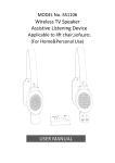
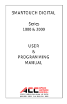
Digital Video Surveillance Center
Management Software
NVClient
User Manual
Revision: V3.2
Updated: 12-2011
User Manual for Digital Surveillance Center Management Software
Contents
Chapter I General ................................................................................................................................. - 3 1.1 INTRODUCTION ............................................................................................................................ - 3 1.2 MAIN FUNCTIONS......................................................................................................................... - 3 Chapter II Software Operating Environment Requirements.......................................................... - 4 2.1 OPERATING SYSTEM .................................................................................................................... - 4 2.2 MINIMUM CONFIGURATION OF HARDWARE ENVIRONMENT .................................................... - 4 2.3 RECOMMENDED CONFIGURATION OF HARDWARE ENVIRONMENT ......................................... - 4 2.4 SOFTWARE ENVIRONMENT CONFIGURATION ............................................................................ - 4 Chapter III Software Installation and Uninstallation ...................................................................... - 4 3.1 SOFTWARE ACQUIREMENT .......................................................................................................... - 4 3.2 SOFTWARE INSTALLATION..........................................................ERROR! BOOKMARK NOT DEFINED.
3.3 SOFTWARE DELETION.................................................................ERROR! BOOKMARK NOT DEFINED.
3.4 SOFTWARE LOGON ....................................................................................................................... - 5 Chapter IV Introduction to Main Interface....................................................................................... - 6 4.1 SYSTEM SETUP AREA ................................................................................................................... - 6 4.2 DEVICE MANAGEMENT LIST AREA ............................................................................................ - 6 4.8 CRADLE HEAD CONTROL AREA.................................................................................................. - 7 4.9 DATE DISPLAY AREA .................................................................................................................... - 7 4.10 IMAGE DISPLAY WINDOW AREA ............................................................................................... - 7 Chapter V: Details for Function Settings ........................................................................................... - 8 5.1 SYSTEM SETUP AREA ................................................................................................................... - 8 5.3 TALKBACK SETUP ...................................................................................................................... - 27 5.4 CRADLE HEAD CONTROL SETUP ...............................................ERROR! BOOKMARK NOT DEFINED.
5.5 IMAGE DISPLAY WINDOW AREA SETUP ....................................ERROR! BOOKMARK NOT DEFINED.
Chapter VI Common Problems in Center Management Software ....... Error! Bookmark not defined.
6.1 UNABLE TO ACCESS THE NETWORK SURVEILLANCE DEVICE VIA THE CENTER MANAGEMENT
SOFTWARE .........................................................................................ERROR! BOOKMARK NOT DEFINED.
6.2 ABNORMAL IMAGE COLOR .........................................................ERROR! BOOKMARK NOT DEFINED.
6.3 CRADLE HEAD AND LENS OUT OF CONTROL ..............................ERROR! BOOKMARK NOT DEFINED.
6.4 NO SOUND WHEN LISTENING ......................................................ERROR! BOOKMARK NOT DEFINED.
6.5 BAD AUDIO EFFECT .....................................................................ERROR! BOOKMARK NOT DEFINED.
Chapter VII Factors Influencing System Performance.................................................................. - 28 -
Chapter I General
1.1 Introduction
Digital surveillance center management software aka. Client Software, is a comprehensive tool for
managing networked surveillance devices including; network video servers, network cameras and
networked digital video recorders. You have complete access to networked devices for centralized
monitoring and storage as well as providing management and control of networked video devices.
This central management software supports video switching of 1, 4, 9, 16, 25, or 36 images,
bi-directional audio, log retrieval, alarm control, and remote retrieval playback. Powerful
functionality, a user friendly interface, and easy operation makes this software ideal for small and
medium sized surveillance systems.
1.2 Factors Influencing System Performance
When designing a system, you must consider the performance of the entire system, the factors
influencing your system, and the settings making your system operate at an optimized
performance level. Bandwidth is your primary consideration, other factors such as frame rate and
an excess of connections to the central management software will influence the frame rate of the
server. Heavy traffic on the network will slow video transmission while the connection to the
servers (DVRs) will also slow the network for other users. One last factor to consider is the
capability of the PC hosting the center management software. Motion video is resource intensive
for a PC, use of a PC with a powerful CPU, maximum RAM and a good graphics card will result
in a better experience with your central management software connection.
1.3 Main Functions
The main functions of this center management software include:
¾ Simultaneously display of up to 36 cameras
¾ Centralized monitoring, storage, data transmission, management and control of all front-end
network video surveillance devices, including network video servers, network cameras, and
networked DVRs
¾ Real-time video monitoring
¾ Video recording modes; pre-video recording, manual video recording, alarm contact video
recording, and timer-controlled video recording
¾ PTZ control, presets, call, and cruise
¾ Supports preset position call when triggered by external alarm
¾ Supports video-loss alarm, video motion alarm, and network error alarm
¾ Log management
¾ Back-end snapshot and front-end snapshot
¾ DDNS(Dynamic Domain Name System)
¾ PPPOE (Dial-up Internet Service)
¾ Support data transparent transmission
User Manual for Digital Surveillance Center Management Software
Chapter II Software Operating Requirements
2.1 Operating System
32-bit/64-bit Simplified Chinese/English Windows 2000, Windows 2003, Windows XP/Vista and
Windows 7
2.2 Minimum Configuration of Hardware Environment
CPU: Pentium 2.0 GHz or higher
Memory: 256 MB
Display Card: TNT2
Sound Card: Necessary for bi-directional audio
Hard Disk: Minimum 40G if the video recording is necessary
2.3 Recommended Configuration of Hardware Environment
CPU: Intel Core2 Duo E7400 2.8 GHz or higher
Memory: 2 GB
Display Card: NVIDIA GeForce 9600GSO or equivalant
Hard Disk: SATA Hard Disk; 2 TB with 8 MB or greater cache memory
2.4 Software Environment Configuration
IE 6.0 or later
DirectX9.0 or later
TCP/IP Internet Protocol
Chapter III Software Installation and Uninstallation
3.1 Software Installation
The central management software is included with your DVR and can be found on the included
software CD. Insert the CD into the CD-ROM drive and locate the installation file in the CMS
folder. Double-click the icon to begin installation, Windows will walk you through installation of
the software. When installation is complete you can launch the software by clicking the NVClient
shortcut on your desktop.
If you choose to remove the software you can do so using "Add/Remove Programs" on your
Windows control panel.
User Manual for Digital Surveillance Center Management Software
3.2 Software Logon
The first time you launch NVClient you will set up a User Name and a Password. This username
and password is for NVClient software only and not used to log into your DVR. You will use this
name and password each time you launch NVClient in the future. The password must be at least
six digits.
Username: Enter a username that you will use each time you launch NVClient.
Password: Enter a password that you will use each time you launch NVClient.
Re Input: Confirm the password that you will use each time you launch NVClient.
When you launch NVClient in the future the log-in dialog box below will be displayed. Enter your
username and password for the NVClient software that you entered in the steps above.
User Manual for Digital Surveillance Center Management Software
Chapter IV Introduction to Main Interface
4.1 System Setup Area
Alarm Info: Click to display any information with regard to an alarm event.
Cycle Switch: Click to activate cyclic switching.
Group Switch: Click to manually switch between video groups; see chapter 5.
Local Setup: Click to enter operating settings for the client software; see chapter 5.
Remote Setup: Click to enter operating settings in the DVR.
Playback: Click to enter playback mode. Play files from remote DVR or local PC.
Lock/Unlock: Click to lock or unlock the screen. Unlock you must enter username and password.
4.2 Device Management List Area
This area is used for centralized management and control of
DVRs; see chapter 5.
4.3 Channel Status
Click to display the status
information of the video device
connected to this client software.
User Manual for Digital Surveillance Center Management Software
4.4 Snapshot
Click to capture an image from the video. The image will be saved in the
specified directory of the computer.
4.5 Sound Switch
Click to toggle sound ON and OFF.
4.6 Audio Interaction
Click to talk through a device connected to the DVR. Refer to Voice
Intercom Setup in chapter 5.
4.7 Screen Display Switch
Click to select multi-screen view; 1, 2 x 2, 3 x 3, 4 x 4, 5 x 5, or 6 x 6.
4.8 PTZ Control
This section is intended for control of a PTZ camera.
Functionality includes; pan left/right, tilt up/down, focus
near/far, iris open/close, preset position setup, wiper control,
and auxiliary lighting.
4.9 Date Display Area
This area displays the current system time and date.
4.10 Image Display Window
Real-time display of DVR video images and client settings.
User Manual for Digital Surveillance Center Management Software
Chapter V: Details for Function Settings
5.1 System Setup
5.1.1 Local Setup
The "Local Setup" tab allows you to enter the specific criteria to view and access a network
connected DVR from a PC.
5.1.1.1 Common Setup
5.1.1.1.1 Local Record Disk
Using the network client you can record video to the hard disk on your PC or a hard disk located
on your network. "Local Record Disk" displays the total size of the hard drive and the amount of
space free for file storage.
Check a disk, click "Apply" and the client will automatically create a file folder in the root
directory named "NVFile" on the drive to store video files. All video and images will be saved to
this folder.
User Manual for Digital Surveillance Center Management Software
5.1.1.1.2 User and Password
If you need to modify a password used to log into the client software, you can do so through this
interface. The first time you launch NVClient you will set up the "admin" password. This
username and password is for NVClient software only and not used to log into your DVR. You
will use this name and password each time you launch NVClient in the future. The password must
be at least six digits.
To change a password click on the "UserName" then click "Set Password". You can change the
user name as you like but the authority listed under "Power" will not change. Enter the new user
name, new password, and confirm the password.
5.1.1.1.3 Record Size
You can limit the video recording by file size or time, saving on hard drive resources.
MaxTime: Minimum 1 minute, maximum 720 minutes
MaxSize: Minimum 1MB, maximum 2048MB
Keep Free Space: Controls the amount of hard drive space cannot be used for video recording.
5.1.1.1.4 Server Manage
User Manual for Digital Surveillance Center Management Software
This field displays the settings for DVRs accessible by the client software and allows you to add a
DVR to the list. Under "Server Manage" click on "Add" to enter the Add Server settings interface.
Add Server Tab
Server Type: Click to choose the DVR server type; select 37DVR.
Address: Enter the IP address of the DVR from the network setup menu.
Local Name: Assign a name to easily recognize a DVR if you have more than one.
CMD Port: Enter the port number used on your router to stream video from the DVR.
Stream Type: Select Main Stream.
Enable Auto Logon: Click to allow NVClient to log into the DVR.
Channel Num: Select the active number of channels in the DVR.
User Name: Enter the user name used to log into the DVR.
Password: Enter the password used to log into the DVR.
Search Tab
If you have a large installation, you can search your network for DVRs and IP Cameras. Click
"Search" to bring up a list of video servers located on your network.
User Manual for Digital Surveillance Center Management Software
Select a device from the search box and click "Add", the "Add Server" screen will open. Follow
the steps on the previous page for the "Add Server" tab.
User Manual for Digital Surveillance Center Management Software
5.1.1.1.5 Environment
Enable Prestore Record: The system will save the preset amount of time leading up to an alarm
event.
Enable Auto Reconnect: The system will automatically reconnect to the DVR (server) when it is
available again on the network.
Enable Sound Alarm: The system will emit an audible alarm from the PC to alert that an alarm
event is occurring.
Enable Auto Logon Client: The system will enable you to launch the client software without the
need to enter username and password.
5.1.1.2 Local Picture View
The client software allows you to take "snapshots" of suspicious activity and save the image to
your hard drive. "Local Picture View" is used to browse and view images you have saved.
User Manual for Digital Surveillance Center Management Software
Disk: Search the storage location for an image.
Date: Search for an image picture by the date saved.
Server: Search for an image picture by the DVR (server) name.
Loop Show: Preview the images saved in the disk.
Print: Print the selected picture.
5.1.1.3 Video Switch On Group
Groups allow you to view cameras from multiple DVRs at one time. For example, if you have
several DVRs in your facility you can set a group named "Entrances" and have all exterior door
cameras in the group. Groups can be switched manually or automatically in a cyclical routine.
Note: It is necessary to enable "Auto Logon" for any DVR added to a group.
Group Name
Add: Click "Add" and enter the name you wish to identify the group then click OK.
Modify: Click a group name (highlight in blue) then click "Modify" to change the group settings.
Delete: Click a group name (highlight in blue) then click "Delete" to remove the group.
Channel Setup
Set: Click a channel from the list, click "Set" to add a camera or edit an existing camera
Clear: Click a channel from the list, click "Clear" to remove the camera from the list
Clear All: Click "Clear All" to remove all cameras from the list
User Manual for Digital Surveillance Center Management Software
Option For Switch On Group
This function allows you to set the "Dwell Time", the time a group is displayed on the screen.
Switch Group Cycle Time: Set the "Dwell Time" from 5 to 30 Seconds for groups to display
Open Group On Open Soft
This function allows you to select the group to open first when you launch the client software.
Click the radio button to activate the "Open Group On Open Software" function
Select the group from the list of groups in the drop-down menu that will open first
Example
Set DVR for Auto Logon
1. Click the "Common Setup" tab
2. Click on a DVR to select in the "Server Manage" list
3. Click "Modify" to enter the "Modify Server" setup menu
4. Click "Enable Auto Logon"
5. Enter the number of channels available from the DVR; i.e.: 4, 8, 16…
6. Enter the DVR "User Name"
7. Enter the "Password" associated with the user name
8. Click "OK"
9. Click "Apply" then click "OK" to save settings.
User Manual for Digital Surveillance Center Management Software
Add a Group
1. Click the "Video Switch On Group" tab
2. Click "Add" below the "Group Name" list
3. Assign a recognizable "Group Name"
4. Click "OK"
User Manual for Digital Surveillance Center Management Software
Add Cameras to a Group
For each camera added to a Group, first assign the channel location by clicking on a Channel from
the Channel List.
1. Click on the "Group Name" to assign cameras to that group
2. Click "Set" to select DVRs and Cameras
3. Select a DVR from the Server list
4. Select a Camera from the Channel list
5. Click OK to add to the Group
6. Repeat to add additional cameras to the Group
NOTE: Only DVRs set for "Auto Logon" will display in the "Server Select" drop–down menu.
Set the "Dwell Time" under "Option For Switch On Group"
Select a group to display when you launch the client software
Click "Apply" then click "OK" to save settings.
5.1.1.4 On Time Record
The On Time Record function allows you to set specific days and times NVClient will record from
the DVR to the host computer.
NOTE: Only DVRs set for "Auto Logon" will display in the Server list.
User Manual for Digital Surveillance Center Management Software
Task Setup
Server: Select the DVR/s that you want to record by day and time from the drop-down menu
Channel: Select the channel/s of the DVR that will be recorded
Begin Time: Set the time the client software will begin recording from the DVR
Stop Time: Set the time the client software will end recording from the DVR
Run Fre: Set the frequency to run the task
Delete All: Removes all DVRs from the server list
Add All: Add all servers monitored by the client software and are set for auto logon
Add Task: Click to save the task as set
Modify Task: Click to enter the task and modify the settings
Delete Task: Click to remove the task
5.1.1.5 Service
The Service interface controls interaction between the DVR and an internal or external alarm
device. The client software allows the local PC to react to an alarm event notifying the user and
beginning to record based on set criteria.
User Manual for Digital Surveillance Center Management Software
5.1.1.5.1 Alarm Linkage
Enable Alarm Record: During an alarm the client software can record video to the local PC.
Enable Record On Alarming: Links recording to alarm trigger
Record Time: Set the duration of the recording from 30 to 600 seconds
Server: Select the DVR that will that will trigger recording of an alarm event
Alarm Type: Select Probe Alarm, Motion Alarm, or Video Loss
Channel: Select the video channel an alarm is linked to
Record Channel List: Select the DVR channels to record if an alarm is present
Click "Apply" then "OK" to save settings.
5.1.1.5.2 Alarm Sound Setup
Allows the user to select sounds associated with an alarm event; Motion Detect, Video Loss, and
Probe Alarm.
5.1.1.5.4 Local PC Display
Enable Auto Show Alarm Channel: When logged on and connected to a DVR, this function
allows the client software to open the channel with an alarm event present in full screen mode.
Enable Show Alarm Info: Displays the status of an alarm event on the local PC.
If Break Keep Last Image: Continues to display the last image captured prior to loss of video.
Enable Channel Name As Record Path: Uses the DVR channel name in the file name of
recorded video.
5.1.1.5.5 Hardware Decode
For large installations with multiple DVRs and monitors, this function allows a decoding card to
display the status of a DVR channel. Resolution modes are 640 x 520 and 704 x 576.
User Manual for Digital Surveillance Center Management Software
5.1.1.6 Local Log View
Local Log View provides access to view a data log of all activity on a DVR.
The settings are made as below:
Date: Select the date for the log you wish to review.
Server: Select the DVR for the log you wish to review.
Type: Select the type of information you wish to review; All Information, Alarm Information,
System Operation, Server Operation, or Alarm Read.
Click OK to exit Local Log View.
User Manual for Digital Surveillance Center Management Software
5.1.1.7 Setup Ex
Setup Ex is primarily used to set up communications between the server (DVR) and the PC
running the client software.
5.1.1.7.1 Enable Transparence (Local Com) and Send Com Data to All Server
These functions are primarily used for large surveillance systems that are centrally monitored.
When the "Enable Transparence (Local Com)" function is enabled, the date collected from the
server control port is transmitted to the serial port of the computer in the surveillance center via
the video server's (DVRs) RS-485 or RS-232 interface.
When the “Send Com Data to All Server” function is enabled, you can connect a keyboard to the
serial port of the computer via an RS-485 to RS-232 converter. This will allow direct control of a
PTZ camera connected to the video server (DVR).
It is necessary that the parameters of serial port devices connected to the computer match. The
parameters to be set are; Com, Data Bit, Parity, Rate, and Stop Bit.
5.1.1.7.2 Enable Sync Time On Server Open
Allow synchronization of the server (DVR) time/date with the local PC.
User Manual for Digital Surveillance Center Management Software
5.1.1.7.3 On Start App Auto Open Server
Allow the client software to automatically logon to the video server (DVR) and video encoder that
are preset to auto logon when the client software is opened. Servers that are not set for auto
logon, the client software will attempt auto logon using the default admin username and password.
5.1.1.7.4 Enable Back Connect
This function is primarily used for surveillance systems that incorporate Network Video Servers
and IP Cameras. This function allows the remote video server to make a connection with the client
and report the video data to the client software. The user can connect to the remote video server
without port mapping each server, only the PC hosting the client software.
5.1.1.7.5 Enable Change Screen On Software Start
If the client software does not support the resolution of your display, this function allows the client
software to automatically modify the PC output resolution to allow the software to display in full
screen.
5.1.1.7.6 Open Channel No Show Video On Record Task
Video recording is resource intensive on a PC; to save on PC resources, especially when the PC is
older and not powerful, enable this function. The PC will be able to record multiple channels of
video without viewing live video resulting in smoother video recordings.
5.1.1.7.7 Start Record On Open Channel
After logon to the video server (DVR) and opening a video channel, the client software will
automatically start recording.
5.1.1.7.8 Use Overlay Show Video Stream
Select this option only when using the client software on a powerful PC fitted with a graphics card
featuring graphics hardware acceleration.
Back Connect Settings
Router Settings
Map the port of the computer, hosting the client software, to the wide area network (internet). For
example, port 7777.
User Manual for Digital Surveillance Center Management Software
Network Video Server Settings
Log on to the Network Video Server, open the Network Settings menu, and click the radio button
"Enable Send Notify to NVClient" or "Enable Back Connect". In the box "Object Host" enter the
IP address of the PC hosting the client software.
Port: Input the listen port of client (for example 7777).
Time: The interval that the video server reports the back connection. It is recommended to set the
interval between 3 and 10 seconds.
Click "Save" to save settings.
User Manual for Digital Surveillance Center Management Software
5.1.1.8 Stream Matrix
The stream matrix is used with video decoders where each video decoder matches a channel of
surveillance center. This option is not available for networked DVRs.
Stream Matrix settings:
1. Connect to the video decoder (for detailed information refer to the Decoder user manual).
2. Click the indexes. There are indexes 1 – 96 available.
3. Select the decoder from the "NVD Server" drop-down menu, and then input the Port, Username,
and Password of the decoder.
4. Select the data get mode; Direct Connect or Center Relay.
5. Click "Modify" and then select "Apply" and "OK" to save settings.
User Manual for Digital Surveillance Center Management Software
5.1.1.9 Virtual Matrix
The stream matrix is used with video decoders where each video decoder matches a channel of
surveillance center. This option is not available for networked DVRs.This option makes the video
encoder channel match the video decoder channel.
Virtual Matrix settings:
1. Double click the desired "Video Encode" and select the desired encoder channel.
2. Double click the desired "Video Decode" and select the desired decoder channel.
3. Click "Connect".
4. Click "OK" to save settings.
User Manual for Digital Surveillance Center Management Software
5.1.2 Remote Setup
The "Remote Setup" is used to configure functional parameters and to remotely access video
encoders, video servers and DVRs.
5.1.3 Playback
"Playback" controls playback of recorded video files and supports simultaneous playback of four
channels and retrieval of video files.
Functions
Local Search: Search for video files on the local PC
Remote Search: Search for video files on a remote server (DVR)
Server: Select the server containing the video files to search
Channel: Restrict search to a specific channel
Begin Time: Restrict search to a specific beginning time
End Time: Restrict search to a specific ending time
Record Type: Restrict search to a specific recording type
User Manual for Digital Surveillance Center Management Software
5.2 Device Management List Area Setup
The "Device Management List" area is the lower right corner of the screen. In this area you can og
into or out of any server (DVR) on your list.
5.2.1 Pop-Up Menu
Right click on the video server (DVR) or channel (camera) to open the pop-up dialog box.
Refresh: Click to restart the coonection sequence to a server (DVR)
Login Server: Click to into a server (DVR), enter username and password when prompted
Close Server: Click to close the selected server (DVR)
Close Channel: Click to close a camera
Look On: Click to reopen a camera
Sensor Output Setup: Click to configure an external sensor
Sensor Output Control: Click to control an external sensor
Begin Auto-Patrol On All Opening Servers: Click to toggle function On or Off
Stop Auto-Patrol On All Opening Servers: Click to toggle function On or Off
Server Information: Click to modify sever (DVR) log-on settings
Control: Click to open the Remote Setup menu interface
User Manual for Digital Surveillance Center Management Software
5.3 Talkback Setup
The Talk-Back feature is reserved for DVRs that feature intercom capability. The DVR will have
an input for a microphone that will be used by the person monitoring the surveillance system.
Refer to the drawing below for connection of microphone and speakers for an intercom system.
User Manual for Digital Surveillance Center Management Software
Click the microphone icon to open the "Talkback Manager" control interface.
All Server List: Select the server (DVR) you will communicate through
Talk: Click "Talk" tobroadcast your voice through the selected server (DVR)
The screen will display "Talking" when the talk button is pressed and the microphone is active.