1
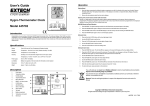
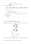
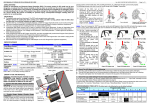
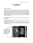
Leah Pruzinsky BME 4910 -‐ Report V March 2nd, 2012 This week my focus has still been in the machine shop trying to accomplish most of our machining work as soon as we can. On Friday Stephany and I came to the machine shop for a little bit to sand off the base edges, because welding leaves excess material on the sides. We also filed down the Plexiglas bath edges as there was excess material from the CNCed part. This takes a little bit to smooth the metal and plastic to give it enough finish. Also on Friday we met with Brittany Depoi about load cells. She was very helpful in explaining the step by step procedure, showing us all of the materials needed and breaking down how to perform the load cell calibration. From this I typed up a report that can be used as a preliminary protocol for calibrating load cells specific to our device, something that can work towards our user manual and also help us when we proceed to calibrating ourselves. This protocol will be updated if anything is missing once we do testing. We are waiting on the load cells to arrive to do the calibration. This write up is attached at the end of the report for reference. On Monday I came in to work on assembling the motor mounts. The method we had chosen for the motor mounts was to have one “L-‐piece” of Aluminum, a 2x2in angle which the motors sit on top of and two legs that were thinner pieces of bent Aluminum. Previously, I had worked on bending the aluminum and punching holes in it to line up with holes in the top L-‐piece and bottom base. However, in working further on this I found the bending to be very inaccurate. I worked on perfecting this method, and got one motor mount assembled and is shown in Figure 1. at the end of this report. After struggling with this I came in on Tuesday to discuss with my partner Stephany. We determined that this would not be a robust method and not accurate enough for our purposes. The top piece had some slight rotation to it and was not very secure. We discussed with Pete and decided on a new alternative to mounting motors. This new method includes more of the 2in angle aluminum (0.125in thick) to support the top piece (made from the same stock). On Tuesday I cut 8 about ¾ in wide pieces of this material. Our new procedure uses two of these pieces screwed into the base and the motor mount top to support it. A picture (Figure 2.) taken simply holding it in position is shown for demonstration. Wednesday I was in the machine shop from 9am to 5pm to work on the motor mounts and other tasks. It took a while to mill the edges and ensure we were cutting exactly even pieces. I worked with Pete to develop a good method. It took a few practices and by the end of the day I was able to complete 5 out of the eight pieces with a width of 0.7 ± .02in. One side was milled first to get an even edge, and then the other side had to be done much more precisely. The pieces were continuously filed so that no burrs would interfere with measurements or alignment. A picture of these finished pieces is shown in Figure 3. I was also able to create a Solid Works drawing demonstrating the hole alignment for these pieces, with one hole to screw into the base, and two holes to screw into the top mount piece (Figure 4.) I sent this to Stephany, who included it into our overall design, also editing the length so that our motor shafts are still in a good location. Also on Wednesday we had a team meeting for all of us to share our progress and individual work for the week. I am responsible for updating the Gantt Chart and finances. I made edits to the Gantt Chart so it matched Team 19’s style to include in the presentation. Finally, on Thursday I am going into the machine shop from about 9am to 12pm to continue working on the motor mount pieces. I hope to finish the remaining pieces and work on drilling the necessary holes along with Stephany. The total time I spent on these tasks this week was 19 hours; breakdown included in our presentation. Figure 1. Mount Assembly Trial #1 Figure 2. Revised mount assembly (demo) Figure 3. Finished Mount arms Figure 4. Solid Works hole placement Load Cell Calibration Background : The Futek Cantilever Load Cell has four wires, 2 input voltages (positive, negative) and 2 output voltages (positive, negative). The wiring diagram is on the spec sheet which can be found via the following link : http://www.futek.com/files/pdf/Product%20Drawings/lbb200.pdf. The wires are put into a female connector, and additional where longer wire strips can be placed as well to make connections. The positive and negative input voltages are connected from the load cell to the female connector, and the longer wire piece connected to a proto-‐board which supplies power from a power supply. The maximum excitation voltage for the load cell is 18V. Next, the two output voltage wire which are in the same female connector have longer additional wiring connected to a male piece. This male piece can be placed in the NI module. The function of the load cell is to measure a voltage (positive and negative) based on the amount of load it is subjected to. This differential output is recorded using NI Data Acquisition (DAQ) in LabVIEW. As different loads are applied, different voltages will result a series of trials and data can be collected. This data will create a voltage vs. mass calibration curve in excel which can be referenced each time the load cell is used. The force on the beam can be calculated simply using Newton’s second law, and the resultant deformations of the tissue will be calculated via Green strain equations. Protocol : 1. Set up the wiring of the load cell according to the specifications sheet, using male / female connector pieces and extra longer wires if necessary. You have two input (excitation) and two output voltages. 2. All four wires will be connected to one female terminal block 3. The output voltages will be connected to a male terminal block which goes into the SCC-‐SG24 module. 2. Carefully clamp the load cell onto a stable surface using an aluminum bar making sure the load is applied in the direction of the groove on the back, also see spec sheet. 3. Make sure that while calibrating it is in the exact position which it will be used during testing and include any additions as well. 4. Tie thread around the bottom two holes and onto the pulley system from which weights will be hung. 5. Once you are set up open the “voltag_force_out3.vi” on the computer in LabVIEW. 6. open the DAQ assistant and choose measurement and automation → Config → Voltage 7. Choose the + icon to add a task → VOLT → Mod1 8. Choose ao or a1 making sure you know where the output wires from the load cell are in the module (the ao slot are the top 2, 6 and 5, and the a1 location is 4 and 3). 9. You will test 5 different weights : 0, 10, 20, 50, and 100g (the max for the load cell is 113g → NEVER exceed this). 10. placing the first weight over the pulley play the VI to record your results, these will be saved in a .txt file and can then be copied into excel. 11. Perform for all weights once through collecting 2000 data points for each, and then repeat two times (for a total of three trials for each weight). 12. In excel, choose the mode of each data collection to represent that set, then take the average of the modes from each of the three trials. 13. Plot these points as a voltage vs. mass graph and find a linear fit equation in excel. 14. Congratulations! This calibration curve can now be used each time you test with this load cell, matching a recorded voltage to a corresponding mass.