1
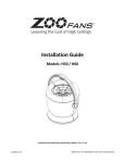
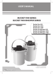
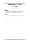
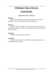
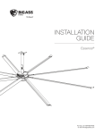
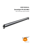
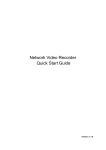
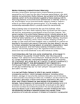
User Manu User Manuall al LIZA Compact Moving Light Enclosures LIZA Projector Enclosures Tempest 11845 Wicks Street Sun Valley, CA 91352, USA Tel +1 818 787 8984 Fax +1 818 252 7101 [email protected] For the following products, manufactured after January 2015 LIZA 6425H LIZA 6450H LIZA 6475H www.tempest.org In the interest of continuous product improvement, the information in this document is subject to change without notice. Neither Tempest Lighting, Inc. nor its representatives or agents may be held liable for expense or injury arising from it. © Tempest Lighting Inc. All Rights Reserved LIZA Enclosure User Manual January 2015 page 1 Declaration of Conformity This is to certify that the following products 64xxH LIZA Projector Enclosures are in Compliance with the following standards or specifications according to the Electro Magnetic Compatibility Directive 2004/108/EC. EN55015, Cispr 16 and are in compliance with the following standards or specifications according to the Low Voltage Directive 2006/95/EC. EN60598-1 This declaration is made by the manufacturer Tempest Lighting, Inc. 11845 Wicks Street, Sun Valley, CA 91352, USA This declaration is based on tests that were conducted on the submitted samples of the above mentioned products. Detailed results can be referred to test reports C27963_11, C27963_12, C27963_13, C27963_14 Dated: January 21st, 2015 Signature . . . . . . . . . . . . . . Tempest Lighting Inc 1 Introduction LIZA Enclosure User Manual page 2 1 Introduction Thank you for purchasing the LIZA projector enclosure. It will serve you for many years, protecting your projector from dust, thieves and vandals, and operating at extremely low sound levels. Products Covered By this Manual: LIZA 6425H 90-264VAC, 50/60Hz LIZA 6450H 90-264VAC, 50/60Hz LIZA 6475H 90-264VAC, 50/60Hz Using This Manual Please read this manual in its entirety before starting work. All the information contained is important, and should be read carefully before proceeding. Heed all warnings and advisories. Icon Key: Valuable information Electrical Warning Safety Information LIZA Enclosure User Manual page 3 2 Installation 2.1 Safety and Warnings These warnings are for your protection. Failure to comply may result in serious injury or death. Tempest Lighting, Inc. assumes no responsibility for damages or injury incurred by misuse or mishandling of product. Do not attempt to install or operate the enclosure before fully reading and understanding this manual Never allow anyone who has not read this manual to open the enclosure or perform maintenance on the equipment within. Never leave the enclosure unattended when open. Always make sure all bolts and latches are tight and safety locks are in place after performing any form of maintenance on the unit. Do not open any electrical boxes until power has been shut off to all supply lines to the enclosure (including the one powering the equipment). Do not open any outdoor enclosure in wet weather. 2.2 Tools and Equipment To install the enclosure, you will need the following items: Crescent wrench Phillips screwdriver Terminal screwdriver Proper wiring installation equipment (for line power and signal wiring) Any equipment listed in the equipment manufacturer’s equipment-specific installation directions LIZA Enclosure User Manual page 4 2.3 Mounting the LIZA Enclosure The LIZA enclosure must be mounted under a solid structure rated for the weight of the enclosure and the equipment inside it. All suspensions over personnel must be approved by the appropriate safety authorities in the jurisdiction of the installation. Tempest Lighting, Inc., its agents and employees will not be held responsible for unsafe installation practices by others. LIZA will generally be installed in three ways: a) In a suspended ceiling, using the industry-standard GrippleTM hardware supplied b) Under a hard ceiling or structure, using four M6 or ¼” bolts or dropper rods c) Suspended from a vertical pole or horizontal pole or truss, using a Tempest XYZ Mount It is the responsibility of the installer to ensure that all mounting points are secure and conform to local safety regulations. Tempest Lighting Inc. accepts no responsibility for damage or injury arising from inappropriate or unsafe installation. LIZA Enclosure User Manual page 5 Suspended Ceiling 1. Remove ceiling tiles 2. Attach the looped ends of all four Gripple wires around structural members above the ceiling tiles. If there are no suitable attachment points, you will need to add them, in accordance with local building codes. Take the looped end of the Gripple wire and thread it around a structural support in the ceiling, rated for the weight of the LIZA enclosure and projector. 20-30˚ 3. IMPORTANT: In order for the projector to be held securely without movement, the Gripple wires must attach to hanging points that are OUTSIDE the footprint of the LIZA enclosure, using an angle 20-30 degrees from vertical. 4. Thread the Gripples onto the four eye bolts on the enclosure base and tighten until the enclosure is level and its base is touching the ceiling T-bars 5. Do not replace tiles until installation is complete. LIZA Enclosure User Manual page 6 Hard Ceiling or Superstructure 1. Remove all four eyebolts, lock nuts and washers from the top of the LIZA enclosure 2. Mark out the ceiling/structure for mounting points and air ducts, according to the drawing below. NOTE: This drawing is the top view. 3. Use the eye bolt holes to attach the LIZA frame to the underside of the ceiling/structure, using M6 or ¼” bolts or dropper rods (not supplied). LIZA Enclosure User Manual page 7 Tempest XYZ Mount There are two types of Tempest XYZ mount, to attach either to a vertical pole or to a horizontal pipe or stage truss. Either way, the XYZ mount allows precise positioning at any angle, with adjustment for pan, tilt and roll. 1. Use a hammer and a screwdriver to remove the four ½” knockouts on top of the LIZA base (see drawing above). 2. Using M12 or ½” hardware, bolt through the LIZA base to the slots on the Tempest XYZ mount. 3. Hang the XYZ mount in accordance with the instructions supplied with it. LIZA with Tempest XYZ Truss Mount. Order Tempest Part # 6500.XYZ.T LIZA with Tempest XYZ Pole Mount. Order Tempest Part # 6500.XYZ LIZA Enclosure User Manual page 8 3 Wiring 3.1 Electrical Preparation All electrical work must be carried out by a properly licensed electrician. Failure to observe this point will void the factory warranty for the Tempest Enclosure and possibly the equipment housed inside. 1 Before starting work, switch off power to the branch circuit, carefully following lockout and tag-out procedures. Failure to do so could cause serious injury or death. 2 Two electrical junction boxes will be required within a short distance of the LIZA enclosure for: AC supply wiring DMX control wiring Your LIZA enclosure is supplied fitted with two cable entry points, for Power and signal cables. The cable entries are suitable for use with standard conduit fittings. US size ½”, international 20mm. All junction boxes must be installed in accordance with local electrical codes and should be located near the permanent installation of the enclosure. The AC supply must be protected by a fuse or circuit breaker of a rating suitable for the equipment. The user may connect the enclosure and the equipment enclosed to the same switched supply, or run them separately, according to preference (see below). Note that for temporary installation, the conduit fittings may be replaced with suitable cable entry glands, at the user’s discretion. LIZA Enclosure User Manual page 9 3.2 Remove the Fan Control Cover, and pull AC and Signal control wires through conduit entries, as shown here. Duplex IEC C13 Outlet LIZA Fan Control Board Power Conduit Entry Signal Conduit Entry Power Connections – Single or Split Feed Single Feed: Enclosure and projector are on the same power circuit. The enclosure will move air in the event that the enclosure gets warm when the projector is off (recommended). The circuit must be fused to protect the projector load plus 40W. Split Feed: Enclosure and projector are on separate power circuits. It is the user’s responsibility to ensure that the enclosure power is on when the projector is in use. In Split feed operation the LINE circuit will pull 40W maximum and the SPLIT circuit must be protected to suit the projector load. IMPORTANT: Split Feed – you MUST cut this link at both ends Line: 90-265VAC Split Feed (Projector Power) 90-265VAC* Neutral Protective Ground/Earth * Split feed is NOT CONNECTED for Single Feed operation Replace the Controller Cover. LIZA Enclosure User Manual page 10 3.3 LIZA Operation The LIZA Fan Controller monitors current going to the projector inside the LIZA enclosure, and also heat inside the enclosure. When it detects that the projector is on and/or the internal temperature is getting warm, LIZA starts to run its fan(s), increasing speed as power and/or heat increases, and reducing fan speed (and therefore noise) whenever possible with a safe margin of error. LIZA Operation is completely automatic. LIZA Enclosure User Manual page 11 4 Mounting the Projector in the LIZA Enclosure This must be done by two people. LIZA is equipped with an innovative and very robust universal projector mount that will safely support any suitable projector, as well as offering precise fingertip alignment of pan, tilt and roll. To mount the projector, first remove the LIZA projector frame: 1. Rotate each of the three blue projector mount cams so that they are clear of the projector mount bolts 2. Lift the three bolts clear of the mounting hooks to remove the projector frame. Projector Mount Hook Projector Mount Bolt 1. Projector Mount Cam Projector Mount Adjustment Knob Set the projector top down (ceiling mode) on a flat surface. It may be helpful to remove the projector feet wherever possible. 2. Determine the layout and thread type of the mounting holes in the projector base. They are usually M4, M5, M6 or M8 (larger projectors). 3. Select the appropriate mounting screws from the LIZA hardware kit. Locate the mounting screw plates (flat plates with three holes). LIZA Enclosure User Manual page 12 4. Lay the mounting frame over the projector and adjust the projector mounting bars to align with the projector mounting holes. 5. Using the mounting screw plates as washers, screw the mounting screws into the projector base. Note that LIZA comes with 20mm (3/4”) mounting screws. Longer screws are easily obtainable if needed. 6. Adjust the frame so that the projector is centered and tighten all screws. 7. Attach the completed frame and projector to the LIZA Base and lock in place by swinging the projector mount cams Projector Mount Cam in closed position back over the projector mount bolt heads. LIZA Enclosure User Manual page 13 4.5 Connect Projector Power and Signal Cables Connect projector signal cables by pulling through the signal conduit entry and terminate per the projector manufacturer’s instructions. LIZA provides two universal IEC C13 outlets to feed your projector an also any ancillary equipment you may need to house in the enclosure. Since no-one ever has an IEC C14 plug handy, we include two for you with your LIZA enclosure! IEC C13 outlets for projector and aux equipment Signal Cable conduit entry Coil any excess cable neatly and wrap with a zip tie to prevent snagging when replacing the enclosure cover. Power up enclosure and test projector. LIZA Enclosure User Manual page 14 5 Finishing Off Attach Ceiling Baffle Hoses (optional) to the air inlet and exhaust hose adapters on top of the LIZA enclosure, stretch them out to full length, and lay them out in the ceiling, in approximately an S pattern. This will further reduce fan and airflow noise, but is not essential to the enclosure’s operation. Clamp the hoses in place with the hose clamps provided. Suspended Ceiling Installations Replace tiles around LIZA, trimming as needed around fixings and air duct hoses. Replace LIZA Cover SAFETY FIRST: THIS MAY TAKE TWO PEOPLE. 1 Check that all four cover latches are open, by turning a quarter turn anti-clockwise, using the 8mm hex key provided. 2 Lift the cover in place and turn each latch clockwise until you hear a positive click. LIZA Enclosure User Manual page 15 6 Maintenance Annually or when changing projector lamp, check the two electrostatic inlet air filters and clean them if necessary. 1 To access the filters remove the two thumb screws above the projector lens and pull out the filter assembly 2 Examine the two filters for dust and grease. They may be washed with warm water and a mild detergent. 3 Obtain replacement filters from your Tempest supplier if needed. Filter Assembly Filters may be washed out with warm wayer and a mild detergent as needed Filter Assembly LIZA Enclosure User Manual page 16 7 Limited Warranty INSPECTION/WARRANTY/RETURNS. A. Customer, at its sole expense, shall inspect all Goods promptly upon receipt and accept all Goods that conform to the specifications or catalog. All claims for any alleged defect in or failure of the Goods or Seller's performance to conform to the Contract, capable of discovery upon reasonable inspection, must be set forth in a written rejection notice detailing the alleged non-conformity, and be received by Seller within thirty (30) calendar days of Customer's receipt of the Goods. Failure by Customer to notify Seller of the alleged non-conformity within thirty (30) days will be conclusive proof that the Goods have been received by Customer without defects or damage, and in the quantities specified on the bill of lading and shall constitute an irrevocable acceptance of the Goods and a waiver of any such claim in connection with the Goods. B. Seller warrants to Customer only that the Goods will be free from defects in material and workmanship at the time of delivery and, subject to the exceptions and conditions set forth below, for the following period (the "Warranty Period"): twelve (12) months from the date of shipment by Seller. Seller may provide additional years of warranty coverage beyond 12 month, at the rate of 2.5% of the net sale price per year, up to a total of four additional years’ coverage beyond the standard 12 month warranty period. Seller will remedy a defect as set forth in paragraph 7 D, below, (the "Warranty"). The Warranty is subject to each of the following exceptions and conditions: 1. Customer must promptly (and in all events within the Warranty Period) notify Seller of any alleged defect in a written notice (the "Notice") which shall set forth the quantity, catalog number, finish, original purchase order number, Seller's invoice number on which Goods were originally billed and a statement of the alleged defect, along with digital photographs showing such defects where feasible. 2. The Warranty shall not apply: (i) to any claimed defect that was capable of discovery upon reasonable inspection and deemed to be waived under paragraph A, above; (ii) to any Goods that have been subject to misuse, abnormal service or handling, or altered or modified in design or construction; (iii) to any Goods repaired or serviced by any person other than Seller's authorized service personnel or to Goods installed other than according to installation instructions, or (iv) with respect to normal wear and tear. 3. Seller makes no Warranty with respect to parts or components that are not the product of Seller, and specifically makes no warranty whatsoever for equipment housed inside enclosure products manufactured by Seller. 4. The Warranty is Seller's exclusive warranty with respect to the Goods. Seller makes no warranties, guarantees or representations, express or implied, to Customer except as set forth in this section. ALL OTHER WARRANTIES, EXPRESS OR IMPLIED, INCLUDING, WITHOUT LIMITATION ANY IMPLIED WARRANTY OF MERCHANTABILITY OR OF FITNESS FOR USE OR FOR A PARTICULAR PURPOSE, ARE HEREBY EXCLUDED AND DISCLAIMED. C. Seller will accept the return of Goods properly rejected under paragraph A, above, or as to which Notice of an alleged breach of Warranty has been timely given and such Goods may be returned to Seller, freight prepaid, but only upon Customer's receipt of Seller's written return material authorization ("RMA") and shipping instructions. The RMA shall be void if the Goods are not received within 45 days after issuance of the RMA. No deduction or credit in respect of any rejected or returned Goods shall be taken until Customer has received Seller's further written deduction or credit/authorization following Seller's inspection to confirm nonconformity or defect. Seller will charge to Customer any and all costs incurred by Seller in connection with the handling, shipping, inspection and disposition of any returned Goods that are determined by Seller not to have been nonconforming upon Delivery or as to which the warranty hereunder is not applicable. D. UPON ANY PROPER RETURN PURSUANT TO PARAGRAPH C, ABOVE, WHETHER IN CONNECTION WITH A REJECTION OF GOODS OR AN ALLEGED BREACH OF WARRANTY AND BASED UPON THE CONDITIONS SET FORTH IN THIS PARAGRAPH 7, SELLER AGREES THAT IT WILL, AS THE SOLE AND EXCLUSIVE REMEDY UNDER THE CONTRACT OR OTHERWISE, FOR ANY NONCONFORMITY OR BREACH OF WARRANTY, AND AT SELLER'S SOLE ELECTION: (i) REPAIR SUCH GOODS; OR (ii) REPLACE SUCH GOODS. LIZA Enclosure User Manual page 17 8 Tempest Product Support. Step 1: First contact your local Dealer for support. Your dealer is best placed to respond quickly to your needs. Step 2: If your dealer is unable to answer your questions please contact Tempest: Tempest Lighting, Inc. 11845 Wicks Street Sun Valley, CA 91352, USA Tel +1 818 787 8984 Fax +1 818 252 7101 [email protected] Visit our web site for current information and specifications: www.tempest.org LIZA Enclosure User Manual page 18