1
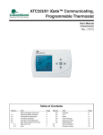
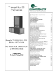
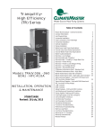
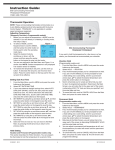
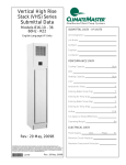
997-060180-1
User’s Manual
ATP32U01, ATP32U02 Programmable Thermostats
ATA32U01 Non-Programmable Thermostats
Menu Driven Display
997-060180-1
Heat Pump Thermostat
User Information
VACATION HOLD (Programmable models only)
1.
From the Main Menu, scroll to MENU and press the center button ■ on
the keypad.
2.
Select HOLD → VACATION
3.
First, the thermostat prompts you for a temperature to hold. If you are in
AUTO MODE you will be prompted for both a heat setting and a cool
setting. Use the up and down arrows keys ▲▼ to select the desired
temperature and press the center button on the keypad.
4.
Next it will prompt you for a date and time that you wish to return to
programmed operation. Returning to the Main Screen, you will notice
that in the upper part of the screen is alternating HOLD TIL *date and
time you specified* and the actual date and time.
5.
To cancel this hold, scroll to CANCEL HOLD from the Main Menu and
press the center button ■.
PERMANENT HOLD (Programmable models only)
1.
From the Main Menu, scroll to MENU and press the center button ■ on
the keypad.
2.
Select HOLD → PERMANENT
3.
First, the thermostat prompts you for a temperature to hold. If you are in
AUTO MODE you will be prompted for both a heat setting and a cool
setting. Use the up and down arrows keys ▲▼ to select the desired
temperature and press the center button on the keypad.
4.
Returning to the Main Screen, you will notice that in the upper part of
the screen is alternating PERMANENT HOLD and the actual date and
time.
5.
You can adjust to permanent hold temperature at will, and the
temperature you select will remain until the permanent hold is canceled.
6.
To cancel this hold, scroll to CANCEL HOLD from the Main Menu and
press the center button ■. This will revert to the programmed settings.
I.
THERMOSTAT OPERATION
ADJUSTING TEMPERATURE (Temporary Override in Programmable
models)
1.
Before you can adjust the temperature, a MODE must be selected. If
you are already in a Heating or Cooling mode, then skip to step 5.
2.
To select a MODE, use the keypad arrows to scroll to MODE, and then
press the center button on the key pad to enter
8/08/05
8:45 AM
OUTDOOR
FAN AUTO
the operating mode menu.
93°
HEATING
3.
Select the desired mode by scrolling up or
down, with the arrows, and then press the
AUTO
SETPOINT
center button on the keypad to enter into that
HEAT 62
COOL 85
mode.
4.
You are now returned to the Main Menu and
RH TEMP MODE FAN MENU
Figure 1 is a similar view. NOTE: Outdoor
temperature is only displayed if an outdoor sensor
Figure1
73°
is installed.
5.
To increase the temperature set point, use the arrow up button. To
decrease the set point, use the arrow down button. Press the center
button on the key pad for the new set point to be effective1.
SETTING DATE AND TIME
1.
From the Main Menu, scroll to MENU and press the center button ■ on
the keypad.
2.
Select SET DATE AND TIME
3.
If your area observes daylight savings time, select AUTO DAYLIGHT
SAVING, scroll to ON, then press the center button ■ to save. You will
be returned to the select SET DATE AND TIME menu. Scroll to SET
DATE AND TIME and press the center button ■ on the keypad.
4.
SET MONTH by using the up and down arrows ▲▼, and then press the
center button on the keypad to save the month.
5.
SET DAY by using the up and down arrows ▲▼, and then press the
center button on the keypad to save the day.
6.
SET YEAR by using the up and down arrows ▲▼, and then press the
center button on the keypad to save the year.
7.
SET HOUR by using the up and down arrows ▲▼, and then press the
center button on the keypad to save the hour.
8.
SET MINUTE by using the up and down arrows ▲▼, and then press
the center button ■ on the keypad to save the minute.
9.
Date and Time are now set. You can return to the Main Menu by
pressing the left arrow key to return to the previous menu.
HOLD SETTING -- Vacation & Permanent (Programmable models only)
This section describes the HOLD functions. You can program the
thermostat to hold the temperature for a period of time. If you want to hold
the temperature for a few hours or a few weeks, your thermostat can
accommodate your schedule.
FAN OPERATION
The thermostat can operate the fan in three ways:
AUTO (on only during heating and cooling calls)
ON (always on)
PROGRAMMED FAN (fan follows the program set in the program
screen) (programmable models only)
1.
From the Main Menu, scroll to MENU and press the center button on the
keypad ■.
2.
Select FAN.
3.
Select the operation you desire as described above.
CHANGING MODES
OPERATING MODE MENU
1.
From the main screen select MODE.
OFF
2.
Select the operating mode you need and press
AUTO
the center button ■.
COOL
NOTE: If selecting EMERGENCY HEAT,
HEAT
EMERGENCY HEAT
the backlight color will change from blue to red
indicating that auxiliary heat is operating instead of
CHANGE MODE ∇∆
⊲ PREVIOUS
the heat pump compressor. Auxiliary/emergency
heat is significantly more expensive to operate than the heat pump
compressor, and should not be selected unless the heat pump compressor is
not operational.
FAHRENHEIT OR CELSIUS
1.
From the Main Menu, scroll to MENU and press the center button ■ on
the keypad.
2.
Select SETINGS → SCREEN SETTINGS → FAHRENHEIT OR
CELSIUS
3.
Select which scale you prefer.
12 OR 24 HOUR CLOCK
Within this menu option, you can change the timed displayed by your
thermostat to 24 Hour time (Military Time).
1.
From the Main Menu, scroll to MENU and press the center button ■ on
the keypad.
2.
Select SETINGS → SCREEN SETTINGS → 12 OR 24 HOUR CLOCK
3.
Select which time base you prefer.
CONTRAST ADJUSTMENT
You can change the contrast level of your thermostat screen to be displayed
to your preference.
1.
From the Main Menu, scroll to MENU and press the center button on the
keypad.
2.
Select SETINGS → SCREEN SETTINGS →CONTRAST
1
Review PROGRAM and HOLD sections to know effects of changing the set point
2
997-060180-1
3.
4.
Use the up and down arrows ▲▼ to increase or decrease the contrast
level.
Press the center button to accept the new setting.
6.
7.
BACKLIGHT ON TIME
This thermostat has a two color backlight feature. Anytime a button is
pressed, the blue backlight stays on for a certain amount of time. A red
backlight is visible if you are selecting Emergency Heat mode. You can
adjust the amount of time the backlight stays on in the menu options.
1.
From the Main Menu, scroll to MENU and press the center button ■ on
the keypad.
2.
Select SETINGS → SCREEN SETTINGS →BACKLIGHT ON TIME
3.
You can change the backlight on time by using to up and down arrows
▲▼. 30, 60, 90, 120, and ON (all the time) are your choices. Press the
center button to save the new backlight on time.
II.
PROGRAMMING YOUR THERMOSTAT (programmable
models only)
PROGRAMMING A DAY OR A SERIES OF DAYS
After selecting the programming screen, you have the option of
programming everyday, weekdays, weekends, or individual days. Once
you’ve selected a certain day to program, a screen appears that allows you
to set the time, heat setting, cool setting, and fan operation for each event.
1.
From the Main Menu, scroll to MENU and press the center button ■ on
the keypad.
PROGRAM MENU
2.
Select PROGRAM
SAVE
3.
You can program each day differently
MONDAY
TUESDAY
WEDNESDAY
by going through each day and
THURSDAY
FRIDAY
personalizing them. Or, you can program
SATURDAY
SUNDAY
EVERY DAY
everyday the same by scrolling to
WEEKDAYS
WEEKENDS
EVERYDAY. Or, you can program
COPY
SELECT OPTION ∇∆
the weekdays or weekends the same by
⊲ PREVIOUS
selecting the appropriate menu item.
4.
To program everyday the same, select
EVERY DAY
EVERYDAY and then press the center
WAKE
HEAT COOL FAN
70
78
AUTO
6:00A
button ■.
LEAVE
8:00A
62
85
AUTO
5.
Using the right arrow button ►, highlight
RETURN
the WAKE time, and change to desired
5:00P
70
78
AUTO
time by using the up and down arrow ▲▼
SLEEP
10:00P 62
82
AUTO
buttons. Move to the next entry by using
SAVE
the right arrow button ►. To change the
⊲ PREVIOUS
HEAT set point, use the up and down
arrows. Continue this process until all settings are to your liking.
6.
To save these setting, scroll to SAVE, and press the center button ■.
COPYING A PROGRAM FROM ONE DAY TO ANOTHER
In the PROGRAM menu, there is an option to COPY. The option can
be used to copy the program from one day to another day. After COPY
is selected, the thermostat will prompt you for which day to copy from.
Next, it will prompt you for which day to copy the program to. After
these selections, it will then confirm what is being copied to where. At
this point you have the option of canceling the copy process, by pressing
◄ to return to the copy menu, or saving what you have by pressing the
center button ■. The SAVED screen will appear returning you to the
copy menu. Pressing ◄ will return you to the PROGRAM menu.
Pressing ◄ again will return you to the MAIN MENU.
V.
ADVANCED SETTINGS
SECURITY LOCKOUT
This thermostat has the option to set security
features to lockout everything but the adjustment
of the temperature or a total keypad lockout.
1.
From the Main Menu, scroll to MENU and
press the center button ■ on the keypad.
2.
Select SECURITY LOCKOUT.
3.
Select whether you want to lockout everything
but TEMP ADJUST ONLY or TOTAL
KEYPAD LOCKOUT.
4.
Either selection will bring you to the Enter Pin
Number screen.
5.
Using the up and down arrows ▲▼, select a
pin number to lock out the thermostat. The
right arrow ► moves you to the next pin digit.
SECURITY LOCKOUT
TEMP ADJUST ONLY
TOTAL KEYPAD LOCKOUT
SELECT OPTION ∇∆
⊲ PREVIOUS
SECURITY LOCKOUT
ENTER PIN NUMBER
0000
CHANGE NUMBER ∇∆
⊲ PREVIOUS
8.
9.
Once you’ve entered the 4-digit pin number, press the center button ■ to
save the pin. The screen will display LOCKED and return to the main
Screen.
Once you return to the Main Screen, in the upper left of the screen will
alternate between LOCKED and the date and time.
If you selected TEMP ADJUST ONLY, you will only be able to adjust
the set point temperature. Any other operation will require the pin
number to unlock the thermostat.
Once unlocked, you’ll have to set a pin number again to lockout the
thermostat again.
OFFSETS
1.
MENU → SETTINGS → OFFSETS
TEMPERATURE OFFSETS
This option allows calibration (or deliberate miscalibration) of the room
temperature sensor(s). There are various reasons why the displayed
temperature would be adjusted to a higher or lower value. NOTE: Do
not adjust for 30 minutes after installation because board may be heated
by handling. The selected number is the number of degrees, plus or
minus, which will be added to actual temperature. The numbers can
range between -5˚ and +5˚. Default values are set to 0˚ offset.
Temperature Offset
Remote Indoor Offset (if sensor is attached)
Outdoor Offset (if sensor is attached)
HUMIDITY OFFSET
This option allows calibration of the humidity sensor. Adjustments can
range between -10% and +10%. Default is 0% offset.
ANTICIPATOR
This adjustment controls the sensitivity and cycle rate of the
thermostat. Higher numbers decrease the cycle rate. Lower numbers
increase the cycle rate. Default value is 4, and the range is 0-9.
DIFFERENTIAL
This adjustment will vary the number of degrees, from the set point,
before a call for heating or cooling is made. Adjustments can range
between 1˚ and 4˚ differential. Default is 2˚ offset. (If your set point is
70˚F in heating, your thermostat will not call for heat until the
temperature is 68˚F, with a 2˚ differential).
CYCLES PER HOUR
This feature will not allow more than the specified number of equipment
cycles per hour. Values can range from 4 or 6 (or 1 cycle every 15 minutes
(default) or 1 cycle every 10 minutes, if 6 is set). Factory default setting is 4.
This default selection will provide optimum performance in nearly all
installations.
MENU → SETTINGS → CYCLES PER HOUR
AUTO CHANGEOVER
With auto changeover, the thermostat automatically switches itself from
heating to cooling, or vise versa, based on the setpoints. When setting up the
thermostat you have to enter both a cooling setpoint and a heating setpoint.
The thermostat will also prevent the user from setting the cooling setpoint
lower than the heating setpoint. Mode is set to AUTO for this operation to
work.
MENU → SETTINGS → AUTO CHANGEOVER
Auto Changeover Time - This setting sets the minimum off time before the
thermostat can change from one mode to another.
Default is 60 minutes. Range is from 0-120 minutes
in 15 minute increments.
Auto or Manual Change – Default is AUTO. If MANUAL is chosen, you will
need to change from heating to cooling or vise versa.
When MANUAL is set, AUTO is removed from the
MODE screen as a choice.
PROGRAM SETTINGS
1.
MENU → SETTINGS → PROGRAM SETTINGS
SMART RECOVERY
Smart recovery is a feature of your thermostat designed to save energy by
gradually adjusting temperatures. When it’s time for a programmed
1
Review PROGRAM and HOLD sections to know effects of changing the set point
3
997-060180-1
temperature change, smart recovery begins working in advance, turning the
system on and off as needed to slowly adjust the indoor temperature.
During these transition periods, you may notice that the actual temperature
and your temperature setting don’t match. That’s smart recovery in action,
adjusting temperatures in small increments for greater energy efficiency.
This is more energy efficient than simply allowing the system to operate at
full capacity until the desired temperature has been met. Smart Recovery
helps avoid excessive use of auxiliary heat when recovering from night
setback in the heating mode.
SERVICE INFORMATION
These screens help an installer or contractor to have
a good understanding of what problems might be
occurring before arriving for service.
SERVICE INFORMATION
FAULT STATUS
SAFETY STATUS
INPUT STATUS
OUTPUT STATUS
TEMPERATURE STATUS
CLEAR FAULT HISTORY
SELECT OPTION ∇∆
⊲ PREVIOUS
EVENTS PER DAY
This is where you can set the number of events per
EVENTS PER DAY
day. (An event is a period of time scheduled with a
4 - RESIDENTIAL
certain heating and cooling setpoint.) For instance if
2 – RESIDENTIAL
you are away from your home from 8am to 5pm,
2 - BUSINESS
make this period of time an event and set the
SELECT OPTION ∇∆
thermostat at an energy saving setting. You have the
⊲ PREVIOUS
option of setting the events per day to 4RESIDENTIAL (4 events), 2-RESIDENTIAL (2 events) or 2-BUSINESS
(2 events).
EVERY DAY
WAKE
HEAT COOL
70
78
6:00A
LEAVE
8:00A
62
85
FAN
AUTO
AUTO
RETURN
5:00P
70
78
AUTO
SLEEP
10:00P
62
82
AUTO
EVERY DAY
DAY
6:00A
NIGHT
10:00P
HEAT COOL
70
78
62
82
EVERY DAY
FAN
AUTO
ACTIVE
6:00A
AUTO
IDLE
10:00P
HEAT COOL FAN
70
78
AUTO
62
SAVE
SAVE
SAVE
⊲ PREVIOUS
⊲ PREVIOUS
⊲ PREVIOUS
4-RESIDENTIAL
(Default)
2-RESIDENTIAL
82
AUTO
2-BUSINESS
SMART HEAT STAGING (HEAT PUMP ONLY)
This will allow the thermostat to engage in 3rd stage heating if needed.
Options are ON or OFF. Default is OFF. Range for this are 0-120 minutes
in 5 minute increments, if set to ON. 30 minutes is the default time. This
is the time before the electric heat is engaged.
COOLING LOCKOUT
When an outdoor temperature sensor is installed, you can set it up so
cooling option doesn’t energize if the outdoor temperature is below a
certain temperature. Ranges for this are NONE (default), 45˚F, 50˚F, or
55˚F.
ELECTRIC HEAT LOCKOUT
When an outdoor temperature sensor is installed, you can set it up so the
electric heat option doesn’t energize if the outdoor temperature is above a
certain temperature. Ranges for this are NONE (default), 5˚F to 60˚F in 5˚
increments.
INTERMITTENT FAN
Temperature conditions can vary widely between the thermostat location
and extremities of the space the thermostat serves. This air stratification
problem can be especially pronounced during mild outdoor conditions
when long periods elapse between space conditioning demands from the
thermostat. This intermittent fan operation can also improve the
performance of air cleaning or special filtration systems that locate the
cleaning or filtration media at the return air side of the fan.
1.
2.
3.
4.
5.
MENU → SETTINGS → INTERMITTENT
INTERMITTENT FAN
NO HEAT OR COOL CALL
FAN
FAN ON TIME
If the FAN hasn’t been on for an hour, the fan
will start cycling based on these times. Default is
MINUTES
OFF. The first screen is the amount of time you
CHANGE SETTING ∇∆
want the fan to be energized. Ranges are OFF, or
⊲ PREVIOUS
5-20 minutes in 5 minute increments.
After entering this time and pressing the center button ■, the next screen
is the amount of time the fan is OFF. Ranges are
INTERMITTENT FAN
0 minutes, or 5-40 minutes in 5 minute
NO HEAT OR COOL CALL
FAN OFF TIME
increments.
After entering this time and pressing the center
button ■ you will be returned to the Setting Menu
MINUTES
screen.
CHANGE SETTING ∇∆
⊲ PREVIOUS
Fan ON and OFF cycles will continue until the
fan has been energized by a call for heating or cooling.
5
10
1
Review PROGRAM and HOLD sections to know effects of changing the set point
4
997-060180-1
INSTALLER
INFORMATION / ADVANCED
FEATURES
SAFETY CONSIDERATIONS
Improper wiring or installation may damage thermostat. Wiring must
conform to local and national electrical codes
WARNING: Before installing thermostat, turn off all power to unit. There
may be more than one power disconnect. Electrical shock can cause personal
injury or death.
INTRODUCTION
The thermostat is a wall mounted, low-voltage thermostat which maintains room
temperature by controlling the operation of a heating and air conditioning
system. Batteries are not required; temperature and mode settings are preserved
with the power off.
INSTALLATION CONSIDERATIONS
The thermostat requires no batteries. The thermostat is not a power stealing
device and MUST have both R and C connected.
INSTALLATION
III.
THERMOSTAT LOCATION
Thermostat should be mounted:
- Approximately 5 ft. (1.5m) from floor.
- Close to or in a frequently used room, preferably on an inside
partitioning wall.
- On a section of wall without pipes or duct work.
Thermostat should NOT be mounted:
- Close to a window, on an outside wall, or next to a door leading
to the outside.
- Exposed to direct light and heat from a lamp, sun, fireplace, or
other temperature-radiating object which may cause a false reading.
- Close to or in direct airflow from supply registers and return-air grilles.
- In areas with poor air circulation, such as behind a door or in an alcove.
IV.
INSTALL THERMOSTAT
1. Turn off all power to unit.
2. If an existing thermostat is being replaced:
A. Remove existing thermostat from wall.
B. Disconnect wires from existing thermostat, one at a time. Be
careful not to allow wires to fall back into the wall.
C. As each wire is disconnected, record wire color and terminal marking.
D. Discard or recycle old thermostat.
NOTE: Mercury is a hazardous waste and MUST be disposed of properly.
3. Separate the front and back pieces of plastic.
4. Route thermostat wires through hole in back piece of plastic. Level plastic
against wall (for aesthetic value only - thermostat need not be leveled for
proper operation) and mark wall through 2 mounting holes.
5. Drill two 3/16-in. mounting holes in wall where marked. (Note: Mounting
holes on thermostat are designed to fit on a horizontal J-box).
6. Secure back plastic to wall with 2 anchors and screws provided making sure
all wires extend through hole in plastic.
7. Connect wires to proper terminal of the connector block in the front plastic.
8. Push any excess wire back into wall. Excess wire inside the thermostat
plastic case can interfere with proper air flow across the temperature sensor.
Seal hole in wall to prevent air leaks. Leaks can affect operation.
9. Snap front and back pieces of plastic together.
10. Turn on power to the unit.
WIRING DIAGRAMS
All excess wire should be pushed back into the wall as far as possible. Excess
wire inside the thermostat plastic case may interfere with the air flow across the
temperature sensor.
NOTES:
1. Single compressor units with CXM control only (No ECM fan) do not use terminal Y2.
2. Thermostat terminal W1 only used for backup electric heat. For residential units,
thermostat terminal is wired to CXM, DXM or ECM
board. For commercial units, thermostat terminal W1 is wired to an external duct heater.
3. For units with ClimaDry modulating reheat, thermostat terminal DH is wired directly to
DXM terminal H.
4. For units with ECM fan, thermostat terminal DH is wired to terminal DH on the ECM
board.
5. For units with ClimaDry and ECM fan, thermostat terminal DH is wired directly to DXM
terminal H (not to the ECM board).
THERMOSTAT CONNECTIONS
C – 24V Common for Control Circuit
DH – Dehumidify Output (ATP32U02 only)
R – 24V Supply for Control Circuit
W1 – Auxiliary Heat
H – Humidifier (ATP32U02 only)
O – Reversing Valve - energized in COOL mode
Y2 – 2nd Stage Compressor / Cooling / Heating
Y1 – 1st Stage Compressor / Cooling / Heating
G – Fan
L – Alarm Input
V – Not Used
A+, B – Not Used.
GND – Ground
OD – Outdoor Temperature Sensor
ID – Indoor Temperature Sensor
VI.
INSTALLER SETTINGS
NOTE: These options are intended to be used by the installer. End users are
not advised to change or modify any of these settings. Doing so may make
your equipment stop working properly and/or may void the warranty of the
thermostat as well as the equipment hooked up to the thermostat. To access
the installer setting menu, the mode must be set to OFF. Then, press both the
up and down arrows keys at the same time for at least 5 seconds to enter the
installer screen.
MODEL CONFIGURATION
Options to select from: HEAT / COOL, Single Stage or Multi Stage
or HEAT PUMP, Single Stage or Multi Stage, Electric or Multi Fuel.
ACCESSORIES
1
Review PROGRAM and HOLD sections to know effects of changing the set point
5
997-060180-1
Each of these options has settings for Cumulative Run Time and Calendar
Time. Messages will flash at the top of the Main screen when these events are
met to alert the owner that it is time service these options.
Air Filter - Cumulative Run Time default is 1000 hours and Calendar Time is
6 months. Values can range from 400-3600 hours for Cumulative
Run Time (in 100 hour increments), or Calendar Time can be set to
OFF, or 3-48 months (in 3 month increments).
Humidifier - Cumulative Run Time default is 0 hours (OFF) and Calendar
Time is OFF. Values can range from 400-3600 hours for
Cumulative Run Time (in 100 hour increments), or Calendar Time
can be set to OFF, or 3-24 months (in 3 month increments).
UV Lamp - Cumulative Run Time default is 0 hours (OFF) and Calendar Time
is OFF. Values can range from 400-3600 hours for Cumulative
Run Time (in 100 hour increments), or Calendar Time can be set to
OFF, or 3-48 months (in 3 month increments).
Air Cleaner - Cumulative Run Time default is 0 hours (OFF) and Calendar
Time is OFF. Values can range from 400-3600 hours for
Cumulative Run Time (in 100 hour increments), or Calendar Time
can be set to OFF, or 3-24 months (in 3 month increments).
INPUT DEALER INFO
Contractors are able to input Brand Name, Model Number, Contractor
Name, and Contractor Phone number into these screens. This way, the
owner could give this information to the contractor so that he would know
what system the owner has prior to the service visit.
1.
2.
3.
4.
INPUT DEALER INFO
DEALER INFO
BRAND NAME
MODEL NUMBER
CONTRACTOR NAME
CONTRACTOR PHONE
SAVE
BRAND NAME
USE ∇∆ TO SCROLL
THRU CHARACTERS
SELECT OPTION ∇∆
⊲ PREVIOUS
CHANGE LETTER ∇∆
⊲ PREVIOUS
ECM - Operates only when there is a cooling call. This logic will allow
thermostat to operate with ECM motor and no ClimaDry option. The ECM
control board works on reverse logic. Reverse logic implies that when the
humidity is greater than the set point, thermostat energizes the DH output with 0
VAC. ECM fan will run at a slower speed when the DH terminal at the ECM
board is energized with 0VAC. When humidity is below setpoint, the 24 VAC
output to the ECM board will return the airflow to normal speed. The ECM
interprets the 0VAC call, which is actually 13.3VAC at the DH terminal on the
ECM control board.
BOTH – Same as the ClimaDry logic.
NONE – The DH output is not active.
REVERSING VALVE OPTION
Option of the reversing valve (O output) being on when in cooling or
heating. Default is COOLING.
RESTORE DEFAULTS
This will allow you to revert to the factory default settings.
A
A
_____________________________
Scroll to the info you want to enter and press the center button ■.
Enter the information by scroll through the characters using the up &
down arrows ▲▼. Once the character you want is set, press the right
arrow ► to move to the next space and begin entering another character.
Once you’ve completed filling out the field, press the center button ■ to
save the entry and return to the INPUT DEALER INFO screen. Repeat
this process for all fields you want saved.
Once all fields have been entered, scroll to SAVE and press the center
button ■.
FAN WITH HEAT OPTION
Options are ON or OFF. This selection determines whether G (fan) output
is to be ON or OFF when W (auxiliary heat) output is ON. ClimateMaster
auxiliary heaters require a separate G signal from the thermostat to turn on the
blower. In this case, select ON.
HUMIDITY OPTION
If your system is setup with a humidifier, or a
dehumidification option (ClimaDry or ECM
dehumidification mode), select the appropriate setting.
CLIMADRY
ECM
BOTH
NONE
HUMIDITY SETTINGS
HUMIDIFY ONLY
DEHUMIDIFY ONLY
BOTH
NONE
SELECT OPTION ∇∆
⊲ PREVIOUS
To adjust the Set Point for Humidification or Dehumidification, Select the RH
from the Main menu. The values can be selected and adjusted from that screen.
NOTE: If you have an outdoor sensor attached to the thermostat, the
Humidification setting is adjusted automatically based on the outdoor
temperature.
CLIMADRY - Operates independent of a cooling call. This logic will allow
thermostat to operate with DXM using the ClimaDry option. Standard logic per
the DIPs on the DXM implies that when the humidity is greater than the set
point, thermostat energizes the DH output with 24 VAC (acts as a dehumidistat).
DH output will be 0VAC when humidity is below setpoint. Reverse logic per the
DIPs on the DXM implies that when the humidity is greater than the set point,
thermostat energizes the DH output with 0 VAC (acts as a humidistat). DH
output will be 24VAC when humidity is below setpoint.
1
Review PROGRAM and HOLD sections to know effects of changing the set point
6