1
Introduction to STM8S BLDC control
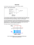
Figure 3.
UM0708
Current mode
CURRENT
REFERENCE
TOINVERTER
LOWSIDE
/PERATIONAL
!MPLIFIER
#URRENT
#OMPARATOR
T
T
CLOCK
SHUNT
34-
-OTOR
6OLTAGE
T
'AIN
SETTING
2.2
0ROGRAMMABLECURRENT
LIMITORCURRENT
REFERENCE
STEPTIME
STEPTIME
44
44
Rotor speed measurement
When the motor is running, the rotating magnetic field of the rotor induces a BEMF signal in
the stator windings. If the motor is intrinsically sinusoidal or trapezoidal, the induced BEMF
signals are periodic, and their frequency is proportional to the frequency of the motor turns.
The proportional coefficient is the number of motor pole pairs.
The motor speed can consequently be calculated by measuring the frequency of the BEMF
signals as shown in Equation 1:
Equation 1
BEMFfreq × 60
Moto ( rpm ) = -----------------------------------------PolePairs
The measurement of the rotor speed is performed by counting the time delay between two
consecutive zero crossings of the BEMF signal. This computation is also called “step time
measurement”. It is implemented in the BLDC firmware by means of a software counter
managed by the timer update interrupt service routine (TIM1 UPD ISR). The TIM1 UPD ISR
routine is executed during each PWM period.
The precision of the step time measurement is always proportional to the PWM period since
zero crossings are sampled only once during each PWM cycle, with the resolution of the
closest cycle.
16/85
Doc ID 15773 Rev 1