1
C ZECH T ECHNICAL U NIVERSITY I N P RAGUE
FACULTY OF E LECTRICAL E NGINEERING
BACHELOR THESIS
Development Methods for the STM32
Microcontroller
Prague, 2009
Author: Jan Svoboda
Declaration
I hereby declare that this bachelor thesis is completely my own work and that I used only the
cited sources.
In Prague 8.6.2009
Jan Svoboda
i
Annotation
Bachealor thesis concern on development methods for the STM32 processor from STMicroelectronics. Provide the overview of avaibale development tools and important features of STM32
processor. Contain example programs to make beginings with processor easier and debugging
tool to support application development with tools provided for free.
Anotace
Bakalářská práce se zabývá metodami vývoje aplikací pro procesoru STM32 od firmy STMicroelectrocnics. Podává prěhled dostupných vývojových nástrojů a důležitých vlastností procesoru
STM32. Obsahuje vzorové programy pro usnadnění prvních kroků s procesorem a základní
ladící nástroj pro podporu tvorby aplikací s využitím volně dostupných nástrojů.
iii
Thanks
I would like to thank those who support me, working on this thesis. Especially to my bachelor
thesis leader Ing. Jan Fischer CSc. for giving me lots of advice and providing me with all
needed materials and documentation.
iv
Contents
List of Figures
vii
List of Tables
ix
List of Shortcuts
x
1
Introduction
1
2
Introduction to STM32 microcontroller
3
2.1
Cortex-M3 processor . . . . . . . . . . . . . . . . . . . . . . . . . . . . . . .
3
2.1.1
Cortex-M3 core . . . . . . . . . . . . . . . . . . . . . . . . . . . . . .
4
STM32 Microcontroller . . . . . . . . . . . . . . . . . . . . . . . . . . . . . .
5
2.2.1
STM32 peripherals overview . . . . . . . . . . . . . . . . . . . . . . .
6
Measured port reading/writing characteristics . . . . . . . . . . . . . . . . . .
8
2.3.1
Maximal pin toggling speed . . . . . . . . . . . . . . . . . . . . . . .
9
2.3.2
Port reading speed with direct software access . . . . . . . . . . . . . .
10
2.3.3
Port reading speed with DMA access . . . . . . . . . . . . . . . . . .
10
2.2
2.3
3
4
Comparison of development tools for STM32 microcontroller
12
3.1
IDE μVision - Keil . . . . . . . . . . . . . . . . . . . . . . . . . . . . . . . .
12
3.2
IDE Ride 7 - Raisonance . . . . . . . . . . . . . . . . . . . . . . . . . . . . .
14
3.3
Primer - Raisonance development platform . . . . . . . . . . . . . . . . . . .
14
3.4
National Instruments for ARM . . . . . . . . . . . . . . . . . . . . . . . . . .
16
3.5
Downloading the code to the microcontroller . . . . . . . . . . . . . . . . . .
17
3.6
My personal opinion on tools selection . . . . . . . . . . . . . . . . . . . . . .
18
Demonstration of STM32 peripherals
19
4.1
Basic I/O and clock setting . . . . . . . . . . . . . . . . . . . . . . . . . . . .
19
4.1.1
RCC - Clock unit . . . . . . . . . . . . . . . . . . . . . . . . . . . . .
20
4.1.2
GPIO - standard I/O ports . . . . . . . . . . . . . . . . . . . . . . . .
23
4.1.3
Main program logic . . . . . . . . . . . . . . . . . . . . . . . . . . . .
24
v
4.2
Timer unit demonstration . . . . . . . . . . . . . . . . . . . . . . . . . . . . .
24
4.3
Debugging with USART unit . . . . . . . . . . . . . . . . . . . . . . . . . . .
26
4.4
ADC unit demonstration . . . . . . . . . . . . . . . . . . . . . . . . . . . . .
28
4.5
Interfacing EEPROM with STM32 I2C unit . . . . . . . . . . . . . . . . . . .
30
4.5.1
I2C EEPROM example description . . . . . . . . . . . . . . . . . . .
32
4.6
Interfacing shift register with STM32 SPI unit . . . . . . . . . . . . . . . . . .
34
4.7
USB based communication with PC . . . . . . . . . . . . . . . . . . . . . . .
38
4.8
Realization of measurement instruments with STM32 . . . . . . . . . . . . . .
41
4.8.1
STM32 ADC unit as voltmeter . . . . . . . . . . . . . . . . . . . . . .
41
4.8.2
Oscilloscope realization with STM32 ADC and DMA . . . . . . . . .
43
4.8.3
Realization of frequency counter with STM32 . . . . . . . . . . . . . .
46
Controlling of stepper motor . . . . . . . . . . . . . . . . . . . . . . . . . . .
49
4.9
5
Monitor STM32
54
5.1
Implementation overview . . . . . . . . . . . . . . . . . . . . . . . . . . . . .
54
5.2
CoreSight unit . . . . . . . . . . . . . . . . . . . . . . . . . . . . . . . . . . .
55
5.2.1
Flash patch breakpoint unit . . . . . . . . . . . . . . . . . . . . . . . .
56
5.2.2
Alternative way of breakpoint implementation . . . . . . . . . . . . .
58
5.2.3
Data Watchpoint and Trace unit . . . . . . . . . . . . . . . . . . . . .
58
5.3
Function description . . . . . . . . . . . . . . . . . . . . . . . . . . . . . . .
59
5.4
Monitor application user manual . . . . . . . . . . . . . . . . . . . . . . . . .
60
5.4.1
Installation . . . . . . . . . . . . . . . . . . . . . . . . . . . . . . . .
61
5.4.2
Debugged application needed modifications . . . . . . . . . . . . . . .
61
5.4.3
Commands overview . . . . . . . . . . . . . . . . . . . . . . . . . . .
63
Possible improvements . . . . . . . . . . . . . . . . . . . . . . . . . . . . . .
64
5.5
6
Summary
66
Bibliography
I
A Content of accompanied CD
II
B List of source codes
III
vi
List of Figures
2.1
Block diagram of Cortex-M3 processor . . . . . . . . . . . . . . . . . . . . .
4
2.2
Block diagram of Cortex-M3 core . . . . . . . . . . . . . . . . . . . . . . . .
5
2.3
Block diagram of STM32 MCU . . . . . . . . . . . . . . . . . . . . . . . . .
6
2.4
Shape of 18 MHz output signal . . . . . . . . . . . . . . . . . . . . . . . . . .
9
2.5
Principle of port reading with DMA access . . . . . . . . . . . . . . . . . . .
11
2.6
Reading speed measurement result (with DMA), f = 100kHz . . . . . . . . . .
11
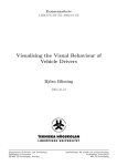
3.1
STM32 Primer 1 . . . . . . . . . . . . . . . . . . . . . . . . . . . . . . . . .
14
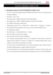
3.2
STM32 Primer 2 . . . . . . . . . . . . . . . . . . . . . . . . . . . . . . . . .
17
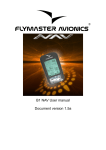
3.3
Flash Loader Demonstrator . . . . . . . . . . . . . . . . . . . . . . . . . . . .
18
4.1
Breadboard with STM32 development board, 3.3 Volt stabilizer and EEPROM
connected via I2C bus . . . . . . . . . . . . . . . . . . . . . . . . . . . . . . .
20
4.2
STM32 RCC unit . . . . . . . . . . . . . . . . . . . . . . . . . . . . . . . . .
21
4.3
STM32 GPIO pin . . . . . . . . . . . . . . . . . . . . . . . . . . . . . . . . .
23
4.4
Timer diagram, internal clock divided by 4, up counting . . . . . . . . . . . . .
25
4.5
USART data frame . . . . . . . . . . . . . . . . . . . . . . . . . . . . . . . .
27
4.6
ADC calibration timing diagram . . . . . . . . . . . . . . . . . . . . . . . . .
29
4.7
I2C data validity . . . . . . . . . . . . . . . . . . . . . . . . . . . . . . . . . .
31
4.8
Terminal user interface of I2C demonstration program . . . . . . . . . . . . . .
31
4.9
I2C example HW realization . . . . . . . . . . . . . . . . . . . . . . . . . . .
32
4.10 I2C demonstration flowchart . . . . . . . . . . . . . . . . . . . . . . . . . . .
32
4.11 EEPROM - Random address read diagram . . . . . . . . . . . . . . . . . . . .
34
4.12 EEPROM - Page write diagram . . . . . . . . . . . . . . . . . . . . . . . . . .
34
4.13 SPI bus interconnection . . . . . . . . . . . . . . . . . . . . . . . . . . . . . .
34
4.14 SPI driven stopwatch HW realization . . . . . . . . . . . . . . . . . . . . . . .
35
4.15 Implementation of LED display driven by SPI bus . . . . . . . . . . . . . . . .
36
4.16 Stopwatch program flowchart . . . . . . . . . . . . . . . . . . . . . . . . . . .
36
4.17 Full speed device with pull up resistor connected to D+ . . . . . . . . . . . . .
39
4.18 STEVAL - ILL015V1 board . . . . . . . . . . . . . . . . . . . . . . . . . . .
39
vii
4.19 Virtual COM Port driver structure . . . . . . . . . . . . . . . . . . . . . . . .
40
4.20 Voltmeter flowchart . . . . . . . . . . . . . . . . . . . . . . . . . . . . . . . .
42
4.21 Oscilloscope application flowchart . . . . . . . . . . . . . . . . . . . . . . . .
44
4.22 NRP viewer 4096 samples of 1 kHz sine wave . . . . . . . . . . . . . . . . . .
46
4.23 Counter application structure diagram . . . . . . . . . . . . . . . . . . . . . .
47
4.24 Counter application flowchart . . . . . . . . . . . . . . . . . . . . . . . . . . .
47
4.25 Stepper motor driver realization . . . . . . . . . . . . . . . . . . . . . . . . .
50
4.26 Stepper motor main program logic . . . . . . . . . . . . . . . . . . . . . . . .
50
4.27 Stepper motor main program logic . . . . . . . . . . . . . . . . . . . . . . . .
51
4.28 Stepper motor half-step control sequence . . . . . . . . . . . . . . . . . . . . .
52
4.29 Stepper motor client application . . . . . . . . . . . . . . . . . . . . . . . . .
53
5.1
Monitor program Flash usage . . . . . . . . . . . . . . . . . . . . . . . . . . .
55
5.2
Monitor program RAM usage . . . . . . . . . . . . . . . . . . . . . . . . . .
56
5.3
Monitor breakpoint event . . . . . . . . . . . . . . . . . . . . . . . . . . . . .
57
5.4
Leaving breakpoint . . . . . . . . . . . . . . . . . . . . . . . . . . . . . . . .
57
5.5
Alternative way of breakpoint implementation . . . . . . . . . . . . . . . . . .
58
5.6
Watchpoint implementation . . . . . . . . . . . . . . . . . . . . . . . . . . . .
59
5.7
STM32 - Monitor, main program logic . . . . . . . . . . . . . . . . . . . . . .
60
5.8
STM32 - Monitor main window . . . . . . . . . . . . . . . . . . . . . . . . .
61
5.9
STM32 - Monitor, Putty setting . . . . . . . . . . . . . . . . . . . . . . . . . .
63
viii
List of Tables
2.1
The most important STM32 documentation . . . . . . . . . . . . . . . . . . .
3
2.2
Measured port reading/writing characteristics . . . . . . . . . . . . . . . . . .
9
3.1
Comparison of the most important IDE for STM32 . . . . . . . . . . . . . . .
13
4.1
Stepper motor PC client commands . . . . . . . . . . . . . . . . . . . . . . .
51
5.1
General commands . . . . . . . . . . . . . . . . . . . . . . . . . . . . . . . .
63
5.2
Watchpoint related command
. . . . . . . . . . . . . . . . . . . . . . . . . .
64
5.3
Watchpoint related command
. . . . . . . . . . . . . . . . . . . . . . . . . .
64
5.4
Memory related command . . . . . . . . . . . . . . . . . . . . . . . . . . . .
64
ix
List of Shortcuts
Shortcut
ADC
ALU
ARR
BKPT
CAN
CRC
DAC
DMA
DWT
EGR
EEPROM
GPIO
FPB
HSE
HSI
IDE
I2C
LSB
MCU
MSB
PLL
PROM
RTC
SDIO
UEV
USB
Description
Analog to digital converter
Arithmetic logic unit
Auto reload register
Breakpoint instruction
Controller–area network
Cyclic redundancy check
Digital-to-analog converter
Direct memory access.
Data Watchpoint and Trace unit
Event generation register - Timer unit
Electrically erasable programmable read-only memory
General purpose I/Os
Flash Patch and Breakpoint unit
High speed external oscillator
High speed internal oscillator
Integrated development environment
Inter-Integrated Circuit bus
Least significant bit
Microcontroller
Most significant bit
Libraries used in examples and programs.
Programmable read-only memory
Real time clock
SD/SDIO MMC card host interface
Update event
Universal serial bus
x
Chapter 1
Introduction
Development in microelectronics is making huge progress nowadays. This also has an effect
on the area of microcontrollers. A few years ago the biggest disadvantage of 32-bit microcontrollers was their price, but today the price of 8-bit and 32-bit microcontrollers has become
almost the same and the gap is going to be unnoticeable in a short time. This is the main reason
the industry is looking to move to 32-bit microcontrollers. Because CTU is the leading technical
university in the Czech Republic, the need to implement these microcontrollers in education instead of 8051 has arisen. Microprocessors 8051 have been used in basic microprocessor courses
until now.
Programming of modern 32-bit microprocessors is not easy to start with. Usually these microprocessors are quite complex and have many peripherals. An example of this complexity might
be the general documentation for STM32F10x - which consists of four documents with more
than 1500 pages altogether. As result of this, it is not possible to learn everything about microprocessor and then start developing as with the 8-bits. Instead, everyone has to study MCU
fundamentals first and then learn other necessary details during the development.
One of the targets of this thesis is to provide beginner with a summary of the most important knowledge about STM32 MCU programming, and to be specific about available development and debugging tools (both hardware and also software) and fundamental STM32 features.
The aim is not to go into depth but to give the reader an overview of topics and allow him to
choose the right IDE, debugger and sources of information right at the beginning.
The most important aim is to describe the behavior of important peripherals and their implementation, to prepare a set of examples and demonstration programs which would make the first
steps with STM32 easier, to write a so called “cookbook” or “howto” on STM32 applications in
1
embedded development. These examples and programs should be easy to understand and help
the reader with all the obstacles which might slowdown his/her progress in microprocessor
studding.
The purpose of this bachelor work lies also in the implementation of USB as a communication
bus between PC and MCU, especially because the RS-232 interface is becoming less available
on new PCs and laptops and modern devices usually provide USB communication interface.
The intention is to provide a communication tool capable of using a PC application based on
serial (COM) communication without the need of hardware USB to RS-232 converter.
Another important aim is to develop a Monitor program (debugging tool). The motivation is
to prepare a software debugging tool which needs no additional hardware on the development
board, only the USART interface. This tool should provide at least a breakpoint capability
and an option to read and modify internal memory and register space.
An important output of this thesis should be to clarify the concept of how to start using STM32
microprocessor in education, to propose a possible prospective modification of the development
board and the selection of the right tool set.
2
Chapter 2
Introduction to STM32 microcontroller
ST Microelectronics is one of the producers offering ARM Cortex-M3 based processor. Other
producers are, for example, Luminary Micro and NXP. This chapter is trying to provide the
reader with fundamental information about STM32 and Cortex-M3 in general. Detailed information can be found in documents listed in table 2.1.
Document name
STM32F103x8/B Data-sheet
RM0008 Reference manual
UM0427 User manual
Cortex™-M3 Technical
Reference Manual
Description
Used microprocessor data-sheet
STM32F101xx, STM32F102xx and
STM32F103xx reference manual
STM32F101xx and STM32F103xx
firmware library
Reference manual for Cortex-M3
core
Table 2.1: The most important STM32 documentation
2.1
Cortex-M3 processor
The Cortex-M3 processor (figure 2.1) is the central processing unit of a Cortex-M3 based MCU.
In addition, a number of other components are required for the whole Cortex-M3 based microcontroller. Chip manufacturers license the ARM Cortex-M3 processor and put this processor in
their silicon designs, adding memory, peripherals, I/O’s and other features. These are different
based on MCU manufactures but the core, including interrupt handling and memory map, will
be the same.
3
Figure 2.1: Block diagram of Cortex-M3 processor
2.1.1
Cortex-M3 core
The central CM3Core is based on the Harvard architecture (physically separate storage and
signal buses for instructions and data). The processor differs from the von Neumann architecture based ARM7 family of processors which use the same signal and memory bus for both
instructions and data.
The core pipeline has 3 stages: Instruction Fetch, Instruction Decode and Instruction Execute.
The processor fetches the branch destination instruction during the decode stage itself. Later,
during the execute stage, the branch is resolved and deal which instruction is to be executed
next. If the branch is not to be taken, the next sequential instruction is already available. If the
branch is to be taken, the branch instruction is made available at the same time as the decision
is made, restricting idle time to just one cycle [1].
The CM3Core contains a decoder for Thumb and Thumb-2 instructions, an ALU with support
for hardware multiply and divide, control logic and interfaces to the other components of the
processor (figure 2.2). The Cortex-M3 is a 32-bit processor, with a 32-bit wide data path,
register bank and memory interface. There are 13 general-purpose registers, two stack pointers,
a link register, a program counter and a number of special registers including a program status
4
register [1, 2].
The Cortex-M3 processor supports two operating modes, Thread and Handler and two levels
of access for the code, privileged and unprivileged, enabling the high security of the developed
application.
The Cortex-M3 processor is a memory
mapped system with a simple, fixed memory map for up to 4 gigabytes of addressable memory space with predefined,
dedicated addresses for code (code space),
SRAM(memory space),
external memo-
ries/devices and internal/external peripherals.
There is also a special region to provide for
vendor specific addressability. The processor
Figure 2.2: Block diagram of Cortex-M3 core
also enables direct access to single bits of data
in simple systems by implementing a tech-
nique called bit-banding. The memory map includes two 1MB bit-band regions in the SRAM
and peripheral space that map on to 32MB of alias regions. Load/store operations on an address in the alias region directly get translated to an operation on the bit aliased by that address.
Additionally, this operation is atomic and cannot be interrupted by other bus activities [1].
Traditional ARM7 based systems support only aligned data access, allowing data to be stored
and accessed only along aligned word boundaries. The Cortex-M3 processor implements unaligned data access that enables unaligned data transfers in a single core access. When unaligned transfers are used, they are converted into multiple aligned transfers and remain transparent to application programmers [2, 1].
In addition the Cortex-M3 processor supports 32-bit multiply operations in a single cycle and
also supports signed and unsigned divide operations with the SDIV and UDIV instructions that
take between 2 and 12 cycles depending upon the size of the operands [2].
2.2
STM32 Microcontroller
ST Microelectronic have their solution based on Cortex-M3 processor - STM32 Microcontroller. There are four main production lines (101, 103, 105 and 107) of STM32. These production lines differ in integrated peripherals. All versions are provided with different flash and
5
RAM size and also different kinds of packages. But the fundamental structure is similar for all
of these MCU (figure 2.3).
Figure 2.3: Block diagram of STM32 MCU
The following section will sum-up STM32 features and important facts useful for microprocessor application point. I would like to emphasize that details can be found in [3, 4].
2.2.1
STM32 peripherals overview
STM32 contain peripherals base on aforementioned production line and also on device density.
Between standard peripherals we can find Timer, USART, USB, ADC, SPI and IIC. These basic
peripherals are explained in more detail in chapter 4. In addition to these STM32 peripherals
also include 1 :
• CRC calculation unit
The CRC (cyclic redundancy check) calculation unit is used to get a CRC code from a
32-bit data word and a fixed generator polynomial.
• Backup registers
These registers could be used to store some setting information while the microprocessor
1 Summary
of information available in document[3]
6
is without power. Registers are secured against random deletion. The backup registers
are forty two 16-bit registers for storing 84 bytes of user application data. They are
implemented in the backup domain that remains powered on by VBAT when the VDD
power is switched off. They are not reset when the device wakes up from Standby mode
or by a system reset or power reset.
• DMA controller
Direct memory access (DMA) is used in order to provide high-speed data transfer between peripherals and memory as well as memory to memory. Data can be quickly moved
by DMA without any CPU actions. This keeps CPU resources free for other operations.
• DAC unit
The DAC module is a 12-bit, voltage output digital-to-analog converter. The DAC can be
configured in 8- or 12-bit mode and may be used in conjunction with the DMA controller.
• RTC unit
The real-time clock is an independent timer. The RTC provides a set of continuously
running counters which can be used, with suitable software, to provide a clock-calendar
function. The counter values can be written to set the current time/date of the system.
• Watchdog unit
The STM32F10xxx has two embedded watchdog peripherals which offer a combination
of high safety level, timing accuracy and flexibility of use. Both Watchdog peripherals (Independent and Window) serve to detect and resolve malfunctions due to software
failure, and to a trigger system reset or an interrupt (window watchdog only) when the
counter reaches a given timeout value.
• Flexible static memory controller
The FSMC block is able to interface with synchronous and asynchronous memories and
16- bit PC memory cards. Translate the AHB transactions into the appropriate external
device protocol and meet the access timing requirements of the external devices.
• SDIO interface
The SD/SDIO MMC card host interface (SDIO) provides an interface between the AHB
peripheral bus and Multimedia Cards (MMCs), SD memory cards, SDIO cards and CEATA devices.
7
• CAN controller
The Basic Extended CAN peripheral, named bxCAN, interfaces the CAN network. It
supports the CAN protocols version 2.0A and B. It has been designed to manage a high
number of incoming messages efficiently with a minimum CPU workload. It also meets
the priority requirements for transmit messages.
This bachelor thesis is based on F101/103 product line, but there are also F105/107 product
lines which include additional features:
• USB 2.0 OTG
Implement USB 2.0 OTG concept that a ’Device’ can perform both the master and slave
roles, and so subtly changes the terminology. STM32 provide Full Speed 12 Mbps USB
2.0 OTG.
• Ethernet
Ethernet MAC 10/100 Mbps with Precise Time Protocol IEEE1588 HW support.
• Dual CAN 2.0
Extend CAN capability up to 2 interfaces.
• Audio Class I2S
Up to 2 Audio Class I2S interfaces. Providing (16-32bit data) Master Clock support with
better than 0.5% accuracy and Audio sampling frequencies from 8 kHz to 96 kHz.
2.3
Measured port reading/writing characteristics
In the point of view of measurement technologies and interaction with sensors the maximal
input/output capabilities of STM32 are very important. For this reason I made a few measurements to provide valid information about input/output speed possibilities of STM32. The
problem with these characteristics is that it is quite difficult to find them in official ST Microelectronics material. Port writing speed was measured by direct program port writing. Reading
speed was measured in two ways. First direct program port reading and then reading of the port
with DMA in memory-to-memory mode. Results of measurements are summarized in table 2.2.
Source codes of all testing programs are available on accompanying CD.
8
Direct port access
Access with DMA
Input/reading speed
9 MHz
6 MHz
Output/writing speed
18 MHz
———
Table 2.2: Measured port reading/writing characteristics
:
2.3.1
Maximal pin toggling speed
One of the important processor characteristics is maximal pin toggling speed2 . One output pin
was toggled and the output signal was watched on the oscilloscope. The pin was toggled by
following algorithm:
while(1)
{
GPIOx->ODR = 0x00000001;
GPIOx->ODR = 0x00000000;
//repeated about 500 times
GPIOx->ODR = 0x00000001;
GPIOx->ODR = 0x00000000;
}
The frequency/speed I was able to reach was 18 MHz. This information was also confirmed in
STM32 presentation materials. The shape of the signal is on the scope screen-shot (figure 2.4).
Figure 2.4: Shape of 18 MHz output signal
2 Test
didn’t concern on maximal possible PWM frequency.
9
2.3.2
Port reading speed with direct software access
In a similar way to the writing speed, the reading speed was measured. Principle of measurement is in reading input data register of given port (the squared signal from the generator was
attached to one of the pin’s on the port) and storing results into the internal RAM, when sufficient number of samples has been taken. The readings were terminated and data were sent
in to PC. On computer data was viewed in Ing. Pribula NRP viewer (in logic analyzer mode)
(figure 2.6) and from number of samples per period of signal the reading speed was calculated
(equation 2.1).
Reading Speed = samples/period ∗ f [sampes/second ]
(2.1)
The maximal reading speed I was able to reach with this approach was about 9 MHz. The
principle of software realization of the port reading is proposed here:
PortInputValues[0] = GPIOA->IDR;
PortInputValues[1] = GPIOA->IDR;
................................
PortInputValues[62] = GPIOA->IDR;
PortInputValues[63] = GPIOA->IDR;
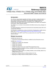
2.3.3
Port reading speed with DMA access
Also another approach to implement the port reading was tested. This measurement (figure 2.5)
was (instead of direct reading) based on memory to memory DMA transfer. Once the DMA
was initiated, 1024 samples were taken and stored into internal RAM. Once the transfer was
terminated data was send in to PC. In the PC data was again shown with Ing. Pribula NRP
viewer (in logic analyzer mode).
10
Figure 2.5: Principle of port reading with DMA access
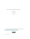
Then the number of samples per signal period were measured and the “sampling” (reading)
frequency was calculated (equation 2.1) in the same way as in the approach without DMA.
This measurement was repeated for different signal frequencies. The maximal reading speed
possible to reach with this approach was 6 MHz. Result on provided figure 2.6 is for frequency
f = 100kHz. Surprisingly the measured reading speed with DMA was 33% less than with direct
input data register reading.
Figure 2.6: Reading speed measurement result (with DMA), f = 100kHz
11
Chapter 3
Comparison of development tools for
STM32 microcontroller
There are many development tools available for STM32 microcontrollers. The aim of this
chapter is to sum-up the advantages and disadvantages of some of them and choose the best one
for the needs of microcontroller’s courses on Department of Measurement on CTU in Prague.
Table 3.1 provide comparison of some of IDE available for STM32.
3.1
IDE μVision - Keil
μVision is the Keil Integrated Development and Debugging Environment. μVision is available for ARM7, ARM9, Cortex-M3, C16x, ST10, XC16x, C251, and C51 embedded microcontrollers. It combines all aspects of embedded project development including source code
editing, project organization and management, revision control, target debugging, simulation
and Flash programming [5].
μVision is a fully commercial product which is quite expensive but on the other side it’s the best
one you can find on the market today. The price of the full version might be as high as a few
thousand US dollars. However a free version is available. This version is quite limited (in
size of compiled application and also maximal size of debugged code) (table 3.1). The biggest
advatage of using this tool is the fact that Keil company is owned by ARM (designer of CortexM3 core). The Keil compiler is considered to be the best one in point of view of output binary
size and application speed.
12
Table 3.1: Comparison of the most important IDE for STM32
13
LabView module
for ARM
Natinal Instruments
EWARN
IAR
RIDE
μVision
Keil
Raisonance
IDE name
Vendor
Keil,
GNU C/C++,
ARM (ADS and RVDS)
GNU C/C++
IAR’s ISO C/C++ and
Extended Embedded C++
Used
compiler
Keil,
GNU C/C++,
ARM (ADS and RVDS)
Keil ULink
Debugging
tools
Keil ULink,
iSYSTEM iC3000,
Hitex Tanto,
Nohau EMUL-ARM
AnbyICE,
J-Link,
ARM RealView ICE,
Macraigor Wiggler,
RDI-based
JTAG interfaces
RLink
unlimited compiler,
<32Kb debugging
60 day
evaluation
30 day
evaluation
or 32 Kb limited
version
Free version
limitation
<32 Kb debugger
<32 Kb compiler
no
yes
yes
yes
yes
Simulator
My personal opinion on Keil μVision is generally positive, but there is reason (described in
section 3.2) why I choose different IDE for this bachelor thesis purposes - RIDE 7.
3.2
IDE Ride 7 - Raisonance
Ride7 is the latest release version of Raisonance Company IDE. This environment is
also a commercial product as the Keil
μVision. On the other side it’s limitation are
less significant than the Keil μVision one (table 3.1). An advantage of Raisonance product is the strong connection to the producer of
STM32 microcontroller – ST Microelectronics. RIDE 7 is one of recommended IDEs by
ST Microelectronics and all source code examples and Libraries published by ST Micro-
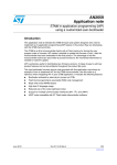
Figure 3.1: STM32 Primer 1
electronics contain RIDE 7 project file. This
makes RIDE 7 the best one IDE for learning STM32 processor.
IDE itself is quite similar to the Keil μVision and it isn’t difficult to transfer from one to the
other. However RIDE 7 supports only one compiler - GNU GCC compiler and only one JTAG
interface - RLINK. This is the biggest disadvantage of RIDE 7. In this point of view Keil
μVision is much handier.
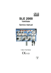
3.3
Primer - Raisonance development platform
I would like also to write a few words about a quite interesting product of Raisonance Company
- STM32 Pimer. The STM32 Primer is an innovative, low-cost evaluation and development
package that is designed to provide an easy introduction to the features of the STM32. The
Primer’s design with MEMS-based controls (navigate by tilting the tool left, right, backward or
forward) and LCD display provide easy control of the included demonstration firmware that includes graphical user interface and games based on the resources of the STM32 microcontroller.
The included firmware (CircleOS task scheduler, system services and demonstration applications) implements low level functions driving the various STM32 peripherals. In addition, it
14
includes features for dynamic loading and management of new applications. All firmware, demos (C sources and projects) and more future applications are available for free download at the
STM32-Primer dedicated site, http://www.stm32circle.com/. STM32 Primer is now available in
two versions. The older one called “STM32 Primer 1” and newer one called “STM32 Primer 2”.
Primer 1 has following features[6]:
• An LCD color monitor (64K colors, 128x128 pixels)
• Two USB connectors:
– "Debug" for connection to a PC running for
programming and debugging
– "STM32" for embedded applications that communicate
with an external USB host
• One push button to switch on the power supply and to launch
menu commands,
• MEMS accelerometer for capture of the 3D-position
information (implemented in navigation controls on the Primer1)
• NiMH batteries for operation when not connected to a host PC
• IrDA transceiver
• Connector for some unused I/O pins
Primer 2 has following features[7]:
• STM32F103E (512 Kbytes Flash)
• Li-Ion battery with smart loading control for improved current
management, battery autonomy (more than 6 hours), charging
time and battery lifespan
• 128x160 pixel touch screen TFT display
• Codec-based audio record and playback with headset connector
and integrated microphone
15
• 4-direction joystick and push button
• 4 additional push buttons based on touch screen capability
• Micro SD card connector
• IrDA transceiver
• 20-pin add-on connector for access to SPI, I2C, USART, CAN
and analog/digital I/Os
• MEMs accelerometer for capture of the 3D-position information
(implemented in navigation controls on the Primer)
• Two USB connectors:
– "Debug" for connection to a PC running for programming
and debugging
– "STM32" for embedded applications that communicate with an
external USB host
I opinion is that the Primer products are great to start with embedded programming, because
almost no knowledge about circuit design is needed. On the other hand programming could
be done on a very low level and it depends on personal choice how many library functions are
going to be used.
3.4
National Instruments for ARM
LabVIEW is a fully featured programming environment produced by National Instruments. It is
a graphical language (called "G") is quite unique in the method by which the code is constructed
and saved. There is no text based code as such, but a diagrammatic view of how the data flows
through the program. Thus LabVIEW is a much loved tool of the scientist and engineer who
can often visualize data flow rather than how a text based conventional programming language
must be built to achieve a task.
LabVIEW programs are called virtual instruments, or VIs, because their appearance and operation imitate physical instruments, such as oscilloscopes and multimeters. LabVIEW contains
16
a comprehensive set of tools for acquiring, analyzing, displaying, and storing data, as well as
tools to help you troubleshoot your code. In LabVIEW, you build a user interface, or front
panel, with controls and indicators. The controls are knobs, push buttons, dials, and other input
devices. Indicators are graphs, LEDs and other displays. After you build the user interface, you
add code using VIs and structures to control the front panel objects. The block diagram contains
this code. In some ways, the block diagram resembles a flowchart.
All this features are available for embedded programming now.
National Instru-
ments together with Keil introduced embedded module for ARM. This module offers
way to program STM32 processor in G language and integrate your embedded design in
LabVIEW[8].
It is effective way of embedded programming. Preparing/programming basic application with minimal knowledge of G language
took me only few minutes. So I would recFigure 3.2: STM32 Primer 2
ommend to everyone who is not interested in
embedded designee itself but need to modify
his application design quite often, to try to use
this solution for embedded programming.
3.5
Downloading the code to the microcontroller
There are many ways to download prepared program in to microcontroller. You can for example
use JTAG interface like RLINK (Raisonance), ULINK (Keil) or others. These tools are usually
quite expensive and their purchase is sometimes related to buying a license for IDE. If you
are not using commercial product with hardware JTAG interface there is a tool called Flash
Loader Demonstrator (figure 3.3). This tool provide Flash writing capability, supports HEX,
Bin and s19 files and also is able to lock STM32 internal memory (write protect). Flash Loader
Demonstrator is available no ST Microelectronics website and copy is also on accompanying
CD.
17
Figure 3.3: Flash Loader Demonstrator
Flash Loader Demonstrator is easy to use and I haven’t had any problems with this tool during
work on this thesis. I think that this tool is very useful and it is very handy. The Flash Loader
Demonstrator uses on-chip USART programming unit [9]. Protocol used by this unit is open to
everyone and available on ST Microelectronic website. So this capability could be used in your
design for firmware update.
3.6
My personal opinion on tools selection
My personal choice was Raisonance RIDE 7. The biggest advantages of this development
tool are the smallest code and debugging limitations between commercial products. But some
problems occurred later during work on this thesis. Simulator in RIDE 7 became sometimes
unstable and so the IDE frees-up. On the other hand I had no other problems with programming
in this integrated development environment.
The ARM module for LabVIEW seems to be quite interesting. With the possibility to be customized for almost any development board, provide NI quite fast tool for design testing. A disadvantage of this tool is the compiled code size but this is the price for the level of abstraction
man has in LabVIEW.
18
Chapter 4
Demonstration of STM32 peripherals
Because Cortex-M3 is a 32-bit RISC processor, it isn’t an easy to start with. Following examples provide step-by-step cookbook how to start developing applications for STM32. Examples
on basic peripheral (GPIO, AD, USART and Timer), were prepared in two versions. The first
one use FWLib and the second one use only files “stm32f10x_map.h”, “stm32f10x_conf.h”,
“stm32f10x_type.h”, “cortexm3_macro.s” and standard start-up code. Examples on more sophisticated peripheral (SPI, I2C, USB,....) and complex demonstration programs (Voltmeter,
Oscilloscope, Frequency counter and Stepper motor drive) were prepared only in version with
FWLib 1 . Source codes of all prepared examples are available on the accompanying CD.
The development board prepared by Bc. Viktor Csörgö was used for purposes of this thesis but
all examples are easily portable on another HW 2 .
4.1
Basic I/O and clock setting
When someone starts to study new programming language, there is always a “Hello world!”
program. In embedded word the equivalent to this is LED blinking program. However, the
STM32 (Cortex-M3 generally) is a very complex microcontroller. The first program which was
prepared to explain basic concepts and ideas of STM32 embedded programming also explain
clock setting.
1 Or
other libraries provided by ST Microelectronics company (USBLib,...).
four examples could be also used on second CTU development board prepared by Bc. Roman Táborský
without any modification.
2 First
19
Figure 4.1: Breadboard with STM32 development board, 3.3 Volt stabilizer and EEPROM
connected via I2C bus
4.1.1
RCC - Clock unit
After start-up the microcontroller is using an internal 8 MHz oscillator. But 8MHz is only 1/9of
maximal possible MCU speed. So in my point of view it is important to explain straight at the
beginning how to reach the best possible microcontroller performance.
RCC unit (figure 4.2) provide clock signal for all peripherals. The example provided in this
thesis explains general principles of RCC unit configuration. Detailed information, if needed
for special setting can be found in [3].
The following lines provide a step by step manual of how to set the MCU clock system to
reach maximal 72 MHz speed. These steps probably became part of all programs which are
going to be developed by you. In this manual the 8 MHz HSE must be connected to the MCU.
Information on howto connect the external crystal can be found in [4], and description of used
registers in [3].
20
Figure 4.2: STM32 RCC unit
RCC unit setting to reach full speed performance
• First we need to enable external oscillator and wait until is frequency is stable.
//HSE enable
RCC->CR |= 0x10000;
//wait until HSE stable
while(!(RCC->CR & 0x00020000))
{
}
• Because of Flash operation timing the Flash unit have to be set properly based on system
clock setting.
21
//flash access setup
FLASH->ACR &= 0x00000038;
//mask register
FLASH->ACR |= 0x00000002;
//flash 2 wait state
FLASH->ACR &= 0xFFFFFFEF;
//mask register
FLASH->ACR |= 0x00000010;
//enable Prefetch Buffer
• Then the next step is to set PLL unit. After necessary setup is complete, unit is enabled
and we have to wait until PLL is ready. My solution isn’t robust (we should wait only for
given period of time) but appropriate in this case.
// setup PLL
RCC->CFGR &= 0xFFC3FFFF;
//mask register
RCC->CFGR |= 0x001D0000;
//PPL x 9
RCC->CR
//PPL enable
|= 0x01000000;
// wait till PLL is ready
while(!(RCC->CR & 0x02000000))
{
}
• Now the PLL unit could be chosen as the source of system clock signal.
RCC->CR
|= 0x0000001;
//remaining need setup
RCC->CFGR &= 0xFFBF000F;
//select PPL as system clock
//APB Low-speed prescaler HCLK divided by 2
RCC->CFGR |= 0x005D0402;
//wait till PLL is chose as system clock
while(!(RCC->CFGR & 0x00000008))
{
}
• Enable clock signal for necessary peripherals. In this example we need two I/O ports
based on board type and AFIO unit.
//enable needed clock
RCC->APB2ENR |= 0x0004;
//GPIO PORT A
RCC->APB2ENR |= 0x01;
//AFIO enable
RCC->APB2ENR |= 0x0008;
//GPIO PORT B
22
4.1.2
GPIO - standard I/O ports
Once we finish RCC unit setting we should configure standard I/O ports (exactly pins - all pins
could be configured independently).
Figure 4.3: STM32 GPIO pin
GPIO unit setup
• Disabling the SWJ-DP port - this step is necessary on CTU development board when the
on-board LED is going to be used. It is connected to one of JTAG pins.
//disable the Serial Wire Jtag Debug Port SWJ-DP
AFIO->MAPR &= 0x001FFFFF;
AFIO->MAPR |= 0x04000000;
• Configuration of input pull-up pin (Port B pin 9) used for push button.
//configure (PB9) as input pull up
GPIOB->CRH &= 0xFFFFFF0F;
//mask port
GPIOB->CRH |= 0x00000080;
//push-pull input mode
GPIOB->ODR |= 0x00000200;
//set in pull up mode
• Configuration of output push-pull pin (Port A pin 13) used for onboard LED.
GPIOA->CRH &= 0xFF0FFFFF;
//port in 10MHz general output
GPIOA->CRH |= 0x00100000;
//push-pull mode
23
4.1.3
Main program logic
Program itself configure GPIO and RCC and than control LED stat base on button status:
4.2
Timer unit demonstration
All timer units are based on a 16-bit counter with a 16-bit prescaler and auto-reload register.
The timer counter can be configured as count up, count down or centered counting (count up
then count down). The clock input to the timer counter can be selected from eight different
sources. These include: a dedicated clock generated from the main system clock, a trigger out
clock from one of the other timers or an external clock through the capture compare pins. The
timer trigger inputs and the external clock sources have a gated input to the timer counter which
is controlled by an external trigger pin ETR.
In addition to the basic timer counter, each timer unit has a four channel capture compare unit.
This unit can perform simple capture and compare functions but also has a number of special
modes that allow common operations to be performed in hardware. Each of the timers has both
interrupt and DMA support. The timers could be split in to three groups based on the functionality. Which counter units are available depends on the exact variety of used microprocessor
unit.
Function of timer is going to be explained on provided LED blinking example. Timer is also
used in these examples:
• Counter
• 6_SPI_Stopwatch
24
Figure 4.4: Timer diagram, internal clock divided by 4, up counting
In this example timer is in up-counting mode, that mean the counter counts from 0 to the autoreload value (content of the ARR - Auto-reload register), then restarts from 0 and generates a
counter overflow event. An update event can be generated at each counter overflow or by setting
the UG (Update generation) bit in the EGR (Event generation register) register (by software or
by using the slave mode controller). The UEV (Update event) event can be disabled by software
by setting the UDIS (Update Disable) bit in CR1 (Control register 1) register.
Timer unit setting as timebase for LED blinking program
• First we need to enable clock signal for used Timer (TIM2)
RCC->APB1ENR |= 0x0001;
//TIM2
• Then the timer unit is set to generate Timer events of given frequency:
f=
fintenal clock
ARR ∗ PSC
(4.1)
Two values of ARR register were chosen to generate of two frequencies/timebases (slower
and faster) for LED blinking.
#define SLOWER
1000
#define FASTER
300
#define PRESCALER 65000
In the end the TIM 2 unit is initialized
TIM2->ARR = FASTER;
//setting of TIM2_ARR
TIM2->PSC = PRESCALER;
//setting of TIM2_PSC
TIM2->CR1 = 0x0081;
//enable TIM2 and auto-reload preloade
25
• Than based on counter overflow event flag in Timer SR (Status register) register the LED
status is toggled (flag is cleared on read).
//toggle LED status on overflow event
if(TIM2->SR & 0x0001 != 0)
{
GPIOA->ODR ^= 0x2000;
}
4.3
Debugging with USART unit
The Universal Asynchronous/Synchronous Receiver/Transmitter (USART) controller is the key
component of the serial communications subsystem of computers, MCUs and other devices.
The USART takes bytes of data and transmits the individual bits in a sequential fashion. At the destination, a second USART re-assembles the bits into complete bytes. Serial transmission is
commonly used with modems and for non-networked communication between computers, terminals and other devices. There are two primary forms of serial transmission: Synchronous
and Asynchronous. Depending on the modes that are supported by the hardware, the name
of the communication sub-system will usually include ’A’ if it supports Asynchronous communications and ’S’ if it supports Synchronous communications. Both forms are described below:
• UART Universal Asynchronous Receiver/Transmitter
• USART Universal Synchronous-Asynchronous Receiver/Transmitter
STM32 has up to 3 USART interface and up to 2 additional UART interfaces. These interfaces
are one of the most important from an application development point of view. I think that
everyone who has ever been developing any embedded application will have to agree - UART
communication is a fundamental debugging tool. I will now examine the function. Almost all
examples and application provided use USART for communication with PC especially because
no additional software on PC (not on Windows Vista) is needed.
USART setting as debugging tool
• As usually first the clock signal need to be enable for dedicated USART interface
RCC->APB2ENR |= 0x4000;
//USART1
26
• Then needed I/O ports must be set appropriately
//configure USART1 Tx (PA9) as alternate function push-pull
GPIOA->CRH &= 0xFFFFFF0F;
GPIOA->CRH |= 0x000000B0;
//onfigure USART1 Rx (PA10) as input floating
GPIOA->CRH &= 0xFFFFF0FF;
GPIOA->CRH |= 0x00000400;
• USART unit setting is quite straight forward only the baudrate setting is little bit complicated. The baudrate for the receiver and transmitter are both set to the same value
as programmed in the Mantissa and Fraction values of USARTDIV. USARTDIV is an
unsigned fixed point number that is coded on the USART_BRR register[3].
Baudrate =
fPCLK
16 ∗USART DIV
(4.2)
Register USARTx_BRR contain 12 bit of mantissa and 4 bits fraction. Calculation example is provided for baudrate = 9600 (USARTDIV = 468.75d ):
1. DIV_Fraction = 16*0.75d = 12d => nearest integer 12d = 0x10h
2. DIV_Mantissa = mantissa (468.75d) = 468d = 0x1D4
Figure 4.5: USART data frame
All other values are set based on required communication setting, meaning of particular
values is illustrated on following figure 4.5.
USART1->BRR
= 0x1D4C;
USART1->CR1 &= 0xEFFF;
//baudrate value
//8 data bits
27
USART1->CR2 &= 0xCFFF;
//1 stopbit
USART1->CR1 &= 0xFBFF;
//no parity check
USART1->CR3 &= 0xFCFF;
//HardwareFlowControl disable
USART1->CR1 |= 0x000C;
//Rx,TX enable
USART1->CR1 |= 0x2000;
//USART1 enable
• Now you can send char over USART. In fact this is the fundamental debugging tool in
embedded development (lot of people, including me, use only this debugging tool, also
in quite complex projects).
//send one byte by USART1
USART1->DR = char;
/wait until USART1 DR register is empty
while(!(USART1->SR & 0x00000080))
{
}
The description provided in this chapter is only an illustration of the unit’s capabilities. For communication software on PC I recommend to use Putty, available on address http://www.putty.org,
or Windows terminal which is unfortunately unavailable in new Windows Vista.
4.4
ADC unit demonstration
ADC represent fundamental interface for many sensors and so it’s quite important to understand
it especially on Department of Measurement. The STM32 features up to two independent analogue to digital converters, depending on variant. The ADC has an independent supply which
can be between 2.4V to 3.6V, depending on the package type. The ADC reference is connected
internally to the ADC supply, or brought out to a dedicated pin. The ADC converters offer a
12 bit resolution with a 1 MHz conversion rate. With up to 18 multiplexed channels, 16 can
be available to measure external signals. Of the remaining two, one is connected to an internal
temperature sensor and the second is connected to an internal reference voltage.
28
ADC unit is used in two examples:
• Oscilloscope
• Voltmeter
Implementation description concern on general setting principles
• The samples are taken measured PORT B pin 1
• Clock signal for ADC1 unit have to be enables
RCC->APB2ENR |= 0x0200;
//ADC1
• Than the required pin configuration
//Configure PB1 (ADC Channel 14) as analog input
GPIOB->CRL &= 0xFFFFFF0F;
//mask port and set for anlog input
• And ADC1 configuration
ADC1->CR1 &= 0xFFF0FFFF;
//Independent mode
ADC1->CR1 &= 0xFFFFFEFF;
//Scan conversion mode disable
ADC1->CR2 &= 0xFFFFFFFD;
//Continuous conversion mode disable
ADC1->CR2 &= 0xFFEFFFFF;
//External triger conversion disable
ADC1->CR2 &= 0xFFFFF7FF;
//Data alignment right
ADC1->SQR1 &= 0xFF0FFFFF;
//# of channel = 1
//ADC1 regular channel 14 configuration
ADC1->SMPR1 |= 0x38000000;
//Sample time 239,5 cycles
ADC1->SQR3 &= 0xFFFFFFE0;
//mask and set 9th chanel as first
ADC1->SQR3 |= 0x00000009;
• ADC needs calibration after hardware start-up or reset (figure 4.6)
Figure 4.6: ADC calibration timing diagram
29
//Enable ADC1
ADC1->CR2 |= 0x00000001;
//Enable ADC1 reset calibaration register
ADC1->CR2 |= 0x00000008;
//Check the end of ADC1 reset calibration register
while(ADC1->CR2 & 0x00000008);
//Start ADC1 calibaration
ADC1->CR2 |= 0x00000004;
//Check the end of ADC1 calibration
while(ADC1->CR2 & 0x00000004);
• Now unit is ready to start sampling analogue signal
ADC1->CR2 |= 0x00000001;
//Start ADC1
while(!(ADC1->SR & 0x0002));
//wait until conversion is done
data = ADC1->DR;
//read result
ADC unit is capable to make up to 1 Ms/s. Howto take 1 Ms/s is shown on the Oscilloscope
application on the accompanying CD. Details are provided in chapter 4.8.2.
4.5
Interfacing EEPROM with STM32 I2C unit
I2C bus was developed by NXP (Philips Semiconductors). The I2C interface standard defines
both the electrical layer and protocol layer. The I2C bus uses a bi-directional SCL (Serial Clock
Line) and SDA (Serial Data Lines). Both the SCL and SDA lines are pulled high. No other
lines are specified. Any device may be a Transmitter or Receiver, and a Master or Slave. Data
and clock are sent from the Master. Data is valid while the clock line is high (figure 4.7). The
link may have multiple Masters and Slaves on the bus, but only one Master may be active at any
one time. I2C Slaves may receive or transmit data to the master [10].
30
Figure 4.7: I2C data validity
The I2C bus is used in this example to connect EEPROM (electrically erasable programmable
read-only memory) to STM32. EEPROM is a special type of PROM that can be erased by
exposing it to an electrical charge. Like other types of PROM, EEPROM retains its contents
even when the power is turned off. Also like other types of ROM, EEPROM is not as fast as
RAM.
The AT24C512B EEPROM is used for demonstration of I2C communication. AT24C512B
provides 524,288 bits of serial EEPROM organized as 65,536 words of 8 bits each [11]. This
EEPROM memory is connected to the STM32 I2C1 unit. STM32 provide terminal user interface (figure 4.8) via USART and provide capability of writing and reading string in/from
memory. Write sequence is terminated by pressing of ESC key on terminal keyboard.
Figure 4.8: Terminal user interface of I2C demonstration program
31
4.5.1
I2C EEPROM example description
The hardware realization of example is on the figure 4.9. It’s important to remember that that
the EEPROM is supply from 3,3 V and the I2C lines have to by pulled up also with 3,3 V, but
the STM32 development board is supplied with 5 V.
Figure 4.9: I2C example HW realization
In software realization, there are critical points which are described in more details here. The rest
of the demonstration program is easy to understand from commented source code available on
the accompanying CD or provided simplified flowchart (figure 4.10).
Figure 4.10: I2C demonstration flowchart
Setting I2C peripheral
• Configuration of required I/O pins and RCC unit. It’s quite a common mistake (it happened to me a few times) to not forget to enable clock source for used peripherals and
configure I/O pins properly
//I2C1 GPIO configuration
GPIO_InitTypeDef
GPIO_InitStructure;
32
//Configure I2C1 pins: SCL and SDA
GPIO_InitStructure.GPIO_Pin =
GPIO_Pin_6 | GPIO_Pin_7;
GPIO_InitStructure.GPIO_Speed = GPIO_Speed_50MHz;
GPIO_InitStructure.GPIO_Mode = GPIO_Mode_AF_OD;
GPIO_Init(GPIOB, &GPIO_InitStructure);
• I2C1 interface configuration is similar to the configuration of other interfaces like USART, ADC...
//Deinitialize I2C2 interface
I2C_DeInit(I2C2);
I2C_InitTypeDef
I2C_InitStructure;
//I2C configuration
I2C_InitStructure.I2C_Mode = I2C_Mode_I2C;
I2C_InitStructure.I2C_DutyCycle = I2C_DutyCycle_16_9;
I2C_InitStructure.I2C_OwnAddress1 = I2C1_ADDRESS;
I2C_InitStructure.I2C_Ack = I2C_Ack_Enable;
I2C_InitStructure.I2C_AcknowledgedAddress = I2C_AcknowledgedAddress_7bit;
I2C_InitStructure.I2C_ClockSpeed = I2C_Speed;
//I2C Peripheral Enable
I2C_Cmd(I2C1, ENABLE);
//Apply I2C configuration after enabling it
I2C_Init(I2C1, &I2C_InitStructure);
For demonstration purposes two the most important functions are described
• Random read function
The first complication of this function is in dummy write before reading. First the internal
counter must be set on the appropriate address - write operation (only if the actual value
of internal pointer’s going to be changed) and after that the read operation can start. The
second complication is the need to ask I2C unit to generate STOP condition and disable
ACK before the last byte is read.
33
Figure 4.11: EEPROM - Random address read diagram
• Memory Write function
The write operation is complicated by the fact that the memory supports only 128 byte
page write[10] - all frames could contain only up to 128 byte. So any data buffer will have
to be split in N 128 bytes long parts and these parts are written independently. Also it is
important to not forget to wait for write operation to finish inside the EEPROM before
the next communication starts.
Figure 4.12: EEPROM - Page write diagram
4.6
Interfacing shift register with STM32 SPI unit
The Serial Peripheral Interface Bus or SPI bus is a synchronous serial data link standard, named
by Motorola that operates in full duplex mode. Devices communicate in master/slave mode
where the master device initiates the data frame. Multiple slave devices are allowed with individual slave select (chip select) lines. Sometimes SPI is called a "four wire [3].
Figure 4.13: SPI bus interconnection
In this example four LED panels are driven by SPI via shift register. All panels are connected
to the latch register in parallel but only one is activated at any time. Activation is done by PNP
34
transistors which are controlled by the GPIO pins. The LED panels function as a stopwatch
display (time base is generated by TIM2). Stopwatch is controlled by one push-button.
Figure 4.14: SPI driven stopwatch HW realization
Used in hardware realization:
• 1x latch register - 74HC595
• 4x LED panels - VQE 24 D
• 4x PNP transistor -BC556B
The circuit diagram is on figure 4.14 and realization on breadboard is on figure 4.15.
35
Figure 4.15: Implementation of LED display driven by SPI bus
In a simple LED panel, each LED segment is typically connected with one terminal to its own
pin on the outside of the package and the other LED terminal connected in common with all
other LEDs in the device and brought out to a shared pin. This shared pin will then make up
all of the cathodes (negative terminals) or all of the anodes (positive terminals) of the LEDs in
the device; and so will be either a "Common Cathode" or "Common Anode" device depending
how it is constructed. Hence an 8 segments package will only require nine pins to be present
and connected.
The structure of LED panels is very useful. This allows us to use segments independently,
and reduce the number of necessary wires. The idea is very simple (same as for TV and PC
screens). The human eye is unable to recognize very fast events. So I used one shift register
and PNP transistors as switch for each segment. Each time only one segment is turned on and
shows data. Segments are activated in cycle so it looks like all of them are turned on and show
inputted data. To reduce blinking, data is fetched to the shift register output during short break
between switching from one to another segment.
Figure 4.16: Stopwatch program flowchart
This process of panel display controlling is shown on flowchart figure 4.16. Implementation of
this process brings one problem. It’s necessary to reduce computation, which add delays in to
segment refresh. I solved this problem by using interrupt from TIM2 (time base timer). This
interrupt increase the seconds variable treat possible overflow into minutes variable.
36
Initialization of SPI interface and other important peripherals
• As usual, first we need to enable appropriator clock systems and configure needed GPIO
//Enable SPI1 clock
RCC_APB2PeriphClockCmd(RCC_APB2Periph_SPI1, ENABLE);
//Configure SPI1 pins: NSS, SCK, MISO and MOSI
GPIO_InitStructure.GPIO_Pin = GPIO_Pin_5 | GPIO_Pin_6 | GPIO_Pin_7;
GPIO_InitStructure.GPIO_Speed = GPIO_Speed_50MHz;
GPIO_InitStructure.GPIO_Mode = GPIO_Mode_AF_PP;
GPIO_Init(GPIOA, &GPIO_InitStructure);
• Configuration of SPI interface
SPI_InitTypeDef
SPI_InitStructure;
//SPI1 configuration
SPI_InitStructure.SPI_Direction = SPI_Direction_1Line_Tx;
SPI_InitStructure.SPI_Mode = SPI_Mode_Master;
SPI_InitStructure.SPI_DataSize = SPI_DataSize_8b;
SPI_InitStructure.SPI_CPOL = SPI_CPOL_Low;
SPI_InitStructure.SPI_CPHA = SPI_CPHA_1Edge;
SPI_InitStructure.SPI_NSS = SPI_NSS_Soft;
SPI_InitStructure.SPI_BaudRatePrescaler = SPI_BaudRatePrescaler_32;
SPI_InitStructure.SPI_FirstBit = SPI_FirstBit_LSB;
SPI_InitStructure.SPI_CRCPolynomial = 7;
SPI_Init(SPI1, &SPI_InitStructure);
//Enable SPI1
SPI_Cmd(SPI1, ENABLE);
• Enabling of required interrupt for timer TIM2
//Enable the TIM2 gloabal Interrupt
NVIC_InitStructure.NVIC_IRQChannel = TIM2_IRQChannel;
NVIC_InitStructure.NVIC_IRQChannelPreemptionPriority = 0;
NVIC_InitStructure.NVIC_IRQChannelSubPriority = 0;
NVIC_InitStructure.NVIC_IRQChannelCmd = ENABLE;
NVIC_Init(&NVIC_InitStructure);
37
Displaying number on LED panel:
• Loading char in to shift register via SPI interface is quite straight forward and understandable
//SPI send data
SPI_I2S_SendData(SPI1, ch);
//Wait for SPI1 Tx buffer empty
while (SPI_I2S_GetFlagStatus(SPI1, SPI_I2S_FLAG_BSY) == SET);
Once the data is loaded into the serial input of latch register, they have to be propagated
in to the latch register output by toggling the RCK pin [12].
//Toggle pin A4 to load data in from shift register in to
GPIO_SetBits(GPIOA, GPIO_Pin_4);
delay(0xFF);
GPIO_ResetBits(GPIOA, GPIO_Pin_4);
• Once data has been loaded in shift register output, it could be displayed on the appropriate
LED panel by toggling pin with dedicated NPN transistor.
GPIO_ResetBits(GPIOB, GPIO_Pin_X);
delay(0xFFF);
GPIO_SetBits(GPIOB, GPIO_Pin_X);
The main program logic uses interrupt driven timebase generated by TIM2 and flag to indicate
if time variables have to be update or not. Program loop has 3 states: stopwatch is running,
stopwatch is stopped and stopwatch cleared. These three states are toggled in infinite loop.
4.7
USB based communication with PC
The USB unit is one of most complex macro-cell of STM32 microprocessor. But as we can
see around us, USB it is also one of the most important buses. I don’t expect that USB interface will be part of basic microprocessor courses, so this chapter provides a basic overview
of possibilities and resources for future projects. However, this doesn’t mean that no example
38
program would be provided - the provided example allows the reader to use USB communication in his/her project without any knowledge about USB in general. For details on USB
implementation I would recommend everyone to go through [13].
A USB device must indicate its speed by
pulling either D+ or D- line high to 3,3 V. A
full speed device, (figure 4.17.) will use a pull
up resistor attached to D+. This pull-up resistor will also be used by the host or hub to detect the presence of a device. Without a pull
up resistor, USB host assumes there is nothing connected to the bus. Some devices have
Figure 4.17: Full speed device with pull up re-
this resistor built in their silicon design, then
sistor connected to D+
it can be turned on and off under firmware
control, others require an external resistor.[13]
In STM32 case pull-up isn’t part of silicon design. It must be added externally, so the additional hardware needed for implementation of USB is 1,5 K resistor and USB connector. In
finale design also the static electricity protection might be added it isn’t the case of breadboard
realization.
USB device example use ST Microelectronic Virtual COM Port driver3 . Microcontroller is
waiting in infinite loop until character ’A’ is received via USB and then replayed with “STM32
- USB demonstration”. Example is realized on STEVAL - ILL015V1 board (figure 4.18).
Figure 4.18: STEVAL - ILL015V1 board
This example is prepared to be easily modified for future Virtual COM Port usage in other applications. Virtual COM Port provides the API for USB communication (figure 4.19). Without
3 Virtual
COM Port driver is available on the accompanying CD.
39
any modification of driver and with only a few steps you can use USB Virtual COM Port in
your design.
Figure 4.19: Virtual COM Port driver structure
Using Virtual COM Port in your design:
1. Add the USBLib into your project, the library is available on accompanying CD or it can
be downloaded from ST Microelectronic web site.
2. Add Virtual COM Port dedicated files in to your project:
• serial.c, serial.h
• usb_desc.c, usb_desc.h
• usb_endp.c, usb_endp.h
• usb_istr.c, usb_istr.h
• usb_prop.c, usb_prop.h
• usb_pwrc, usb_pwr.h
• hw_config.c, hw_config.h
3. Add following lines in to your project
#include "hw_config.h"
#include "serial.h"
4. Modify stm32f10x_it - add the following to the beginning of the file
#include "stm32f10x_it.h"
#include "usb_int.h"
extern void USB_Istr(void);
and edit the USB_LP_CAN_RX0_IRQHandler
40
void USB_LP_CAN_RX0_IRQHandler(void)
{
USB_Istr();
}
5. Call Virtual_Com_Setup(); in your application main function after the RCC unit is set
The application must have proper system clock frequency setting - USB unit need 48 MHz. The
driver provides following four functions:
• void Virtual_Com_Setup(void)
Configure the Virtual COM Port driver.
• u8 sendChar(char ch)
Send char to the computer.
• u8 sendString(char *String, u8 numberOfDataToSend)
Send string of given length to the computer.
• u8 readChar(char *ch)
Read one char received from computer.
Now your application is ready to use USB on MCU side. On PC the Virtual COM Port driver
has to be installed before the device is connected. Then the communication is ready to use.
4.8
Realization of measurement instruments with STM32
Following demonstration programs will show how STM32 can be used with no additional circuits as small measurement station. This might be improved in future bachelor thesis, for example as low-cost school measurement board for students.
4.8.1
STM32 ADC unit as voltmeter
A voltmeter is an instrument used for measuring the electrical potential difference between
two points in an electric circuit. This application was prepared to demonstrate possibility to
use STM32 build-in ADC unit together with STM32 communication capability as a voltmeter
device with output on terminal screen. The application was prepared in two versions. One uses
41
as communication interface USB and second USART. The USB version of the application was
prepared for Stelaris Evaluation Board.
In the demonstration application the potentiometer connected to PORT B pin 1 is used as the source
of voltage. The voltage is measured with ADC unit implemented in the same way as in chapter
4.4. In each cycle, voltage is measured with ADC and the sample is send into computer via
USB (Virtual COM Port device) or USART. On the computer, results are shown on the terminal screen. The difference between USB and USART version is only in called communication
functions. The ADC implementation is the same in both voltmeter versions. The application
core (figure 4.20) is explained below.
Figure 4.20: Voltmeter flowchart
Taking one ADC sample and converting it in to string (char array)
• Constant MULTIPLIER is used to calculate voltage value from result of conversion.
#define
MULTIPLIER
805
The constant represent the relation between conversion result and voltage in Volts. It
could be calculated with this equation:
MULT IPLIER =
Ure f [V ]
∗ 1000000
resolution
(4.3)
The operation of multiplying by 1000000 and dividing by 10000 is to have the result in
integer representation and simplified the calculations.
• The conversion result is transfer in volts.
//calculate voltages from AD conversion result
data = ADC_GetConversionValue(ADC1);
data = (data*MULTIPLIER)/10000;
Then the result is converted into char array.
42
//make string from measured volage
str[2] = data % 10 + ’0’;
data /= 10;
str[1] = data % 10 + ’0’;
data /= 10;
str[0] = data % 10 + ’0’;
The conversion result is then send via USB/USART as string of decimals on the terminal screen.
To clear screen before next result is send to the terminal needed number of Backspace character
is send. I also recommend reduce blinking of terminal by adding a short delay after each
conversion loop.
//return cursor
for(i = 0; i < 6; i++ )
{
printChar(0x08);
}
This application is not difficult to understand but explain fundamental concepts how to implement communication with analog sensors like temperature sensors are.
4.8.2
Oscilloscope realization with STM32 ADC and DMA
An oscilloscope is a type of electronic test instrument that allows signal voltages to be viewed
as a two-dimensional graph of one or more electrical potential differences plotted as a function
of time. The oscilloscope is one of the most versatile and widely-used electronic instruments.
Digital oscilloscopes use an ADC and memory to record and show a digital representation
of a waveform, yielding much more flexibility for analysis, and display than is possible with
a classic analog oscilloscope. The following example shows howto implement digital oscilloscope based on STM32 ADC, DMA and internal RAM without any additional circuit required.
STM32 ADC is capable of sampling 1Ms/s in continuous mode with usage of DMA transfer.
ADC is 10-bit but only 8 MSB are used (PC client application is capable to precede only 8 bit
long samples). The signal input in this case is port B pin 1 and the sampled data is sent to the
computer via USART. Then the data is viewed on computer in NRP viewer.
The main program (figure 4.21) first does the initialization of ADC, RCC, USART and DMA
units and then wait for the command to start signal sampling. Once the command is received
43
samples are recorded. After a given number of samples (4096) are taken they are sent via
USART to the computer, where they are proceed and displayed. It’s important to reconfigure DMA after each cycle by calling function DMA_Configuration();. As PC client was used
Ing. Pribula’s NRP viewer. This viewer was chosen, because it’s going to be used in STM32
courses.
Figure 4.21: Oscilloscope application flowchart
Explanation of important application parts
• First the proper configuration of peripheries is needed. For analog-to-digital conversion
ADC1 was used. ADC was configured in continuous mode and the FWLib was used for
configuration.
//ADC1 configuration
ADC_DeInit(ADC1);
ADC_InitStructure.ADC_Mode = ADC_Mode_Independent;
ADC_InitStructure.ADC_ScanConvMode = ENABLE;
ADC_InitStructure.ADC_ContinuousConvMode = ENABLE;
ADC_InitStructure.ADC_ExternalTrigConv = ADC_ExternalTrigConv_None;
ADC_InitStructure.ADC_DataAlign = ADC_DataAlign_Right;
ADC_InitStructure.ADC_NbrOfChannel = 1;
ADC_Init(ADC1, &ADC_InitStructure);
• Provided configuration suppose appropriate clock and GPIO configuration. It’s necessary
to underline here that the fastest ADC performance is not reached if the MCU is running
on 72 MHz but only 56 MHz. So as indicated a different clock setting is required.
//PLL configuration
RCC_PLLConfig(RCC_PLLSource_HSE_Div1, RCC_PLLMul_7);
RCC_PLLCmd(ENABLE);
• Oscilloscope input pin configuration is required.
44
//Configure PB1 (ADC Channel 9) as analog input
GPIO_InitStructure.GPIO_Pin = GPIO_Pin_1;
GPIO_InitStructure.GPIO_Mode = GPIO_Mode_AIN;
GPIO_Init(GPIOB, &GPIO_InitStructure);
• DMA was configured as shown below to transfer data from ADC1 in to RAM memory.
Details on setting are provided in [3].
//DMA channel1 configuration
DMA_DeInit(DMA1_Channel1);
DMA_InitStructure.DMA_PeripheralBaseAddr = ADC1_DR_Address;
DMA_InitStructure.DMA_MemoryBaseAddr = (u32)ConvertedDataValue;
DMA_InitStructure.DMA_DIR = DMA_DIR_PeripheralSRC;
DMA_InitStructure.DMA_BufferSize = COUNT_SAMPLES;
DMA_InitStructure.DMA_PeripheralInc = DMA_PeripheralInc_Disable;
DMA_InitStructure.DMA_MemoryInc = DMA_MemoryInc_Enable;
DMA_InitStructure.DMA_PeripheralDataSize = DMA_PeripheralDataSize_HalfWord;
DMA_InitStructure.DMA_MemoryDataSize = DMA_MemoryDataSize_HalfWord;
DMA_InitStructure.DMA_Mode = DMA_Mode_Normal;
DMA_InitStructure.DMA_Priority = DMA_Priority_High;
DMA_InitStructure.DMA_M2M = DMA_M2M_Disable;
DMA_Init(DMA1_Channel1, &DMA_InitStructure);
DMA_Cmd(DMA1_Channel1, ENABLE); //Enable DMA channel1
• Once the ADC and DMA are configured they have to be “connected ” together and the ADC
has to be calibrated.
//Enable ADC1 DMA
ADC_DMACmd(ADC1, ENABLE);
//ADC1 regular channel 9 configuration
ADC_RegularChannelConfig(ADC1, ADC_Channel_9, 1, ADC_SampleTime_1Cycles5);
//Enable ADC1
ADC_Cmd(ADC1, ENABLE);
//Enable ADC1 reset calibaration register
ADC_ResetCalibration(ADC1);
//Check the end of ADC1 reset calibration register
while(ADC_GetResetCalibrationStatus(ADC1));
45
//Start ADC1 calibaration
ADC_StartCalibration(ADC1);
//Check the end of ADC1 calibration
while(ADC_GetCalibrationStatus(ADC1));
Oscilloscope function validation
The function of oscilloscope application was validated by sampling of 1 kHz sin wave (figure
4.22) and calculating the sampling rate from sampling result shown in NRP viewer. The 1Ms/s
sampling speed was confirmed by taking 100 samples for 1 kHz sin wave period.
Figure 4.22: NRP viewer 4096 samples of 1 kHz sine wave
4.8.3
Realization of frequency counter with STM32
The conventional counter is a digital electronic device which measures the frequency of an
input signal. It may also have been designed to perform related measurements including the
period of the input signal, ratio of the frequency of two input signals, time interval between
two events and totalizing a specific group of events.[14]Implemented counter is capable of
measuring frequencies from 0 Hz to 1 MHz.
46
The frequency f of repetitive signals is defined by the number of cycles of that signal per unit
of time. It may be represented by the equation:
f = n/t
(4.4)
where n is the number of cycles of the repetitive signal that occurs in time interval t. If t =
1 second, then the frequency is expressed as n cycles per second or n Hertz. As suggested by
the equation 4.4, the frequency f of a repetitive signal is measured by the conventional counter
by counting the number of cycles n and dividing it by the time interval t. The interval t is set
based on measured frequency as explained later.
Figure 4.23: Counter application structure diagram
Counter application uses two timers: one to generate timebase t and a second one to count
incoming signals rising edges. The period t is divided by 2 if the counting timer overflows
or multiplied by two if the counter counts less than 14500 edges (this number was chosen
experimentally to provide reliable functionality of application) (figure 4.24).
Figure 4.24: Counter application flowchart
47
Software realization description
The system clock setting is not provided here (setting is available in on the accompanying CD
or in another timer examples in this thesis). The application requires system clock to be 72
MHz. The counter input is on Port A pin 6.
• Input pin setting - do not forget to enable Port A clock.
//GPIOA Configuration PA6
GPIO_InitStructure.GPIO_Pin = GPIO_Pin_6;
GPIO_InitStructure.GPIO_Mode = GPIO_Mode_IPU;
GPIO_Init(GPIOA, &GPIO_InitStructure);
• The setting of TIM2 used as timebase t.
//Time base configuration
//Timer 2 configuration
TIM_TimeBaseStructure.TIM_Period = PERIOD;
TIM_TimeBaseStructure.TIM_Prescaler = PRESCALER;
TIM_TimeBaseStructure.TIM_ClockDivision = TIM_CKD_DIV1;
TIM_TimeBaseStructure.TIM_CounterMode = TIM_CounterMode_Up;
TIM_TimeBaseInit(TIM2, &TIM_TimeBaseStructure);
The setting of TIM3 used as the counter of rising edges.
//Input counter configuration
//Timer 3 configuration
TIM_TimeBaseStructure.TIM_Period = 30000;
TIM_TimeBaseStructure.TIM_Prescaler = 0;
TIM_TimeBaseStructure.TIM_ClockDivision = TIM_CKD_DIV1;
TIM_TimeBaseStructure.TIM_CounterMode = TIM_CounterMode_Up;
TIM_TimeBaseInit(TIM3, &TIM_TimeBaseStructure);
TIM_TIxExternalClockConfig(TIM3, TIM_TS_TI1FP1, TIM_ICPolarity_Rising, 0x5);
In the end the Timer units have to be enabled.
TIM_ClearFlag(TIM2, TIM_FLAG_Update);
//TIM enable counter
TIM_Cmd(TIM2, ENABLE);
TIM_Cmd(TIM3, ENABLE);
48
• The algorithm of counting the number of rising edges and getting the result.
//needed preparion of timers
TIM_ClearFlag(TIM3, TIM_FLAG_Update);
TIM_SetCounter(TIM2, 0x00);
TIM_SetCounter(TIM3, 0x00);
TIM_ClearFlag(TIM2, TIM_FLAG_Update);
//wait until period t is counted
while(TIM_GetFlagStatus(TIM2, TIM_FLAG_Update) == RESET);
//result of frequnecy measuremnt
result = (TIM3->CNT)*prescaler_div;
As well as the algorithm presented above, the logic of controlling the length of period t and all
required setting could be found in the source code available on the accompanying CD. The function of the counter application was validated by measuring the signal of known frequency (from
the signal generator). The measured frequency was about 0.2% higher than the generated one.
This systematic error is most likely due to the uncertainty of external oscillator.
4.9
Controlling of stepper motor
Stepper motors can be found in many technical applications and are quite important electrical
instruments. The following lines are concerned on interfacing stepper motor with STM32 from
a software and also a hardware point of view. The realization consists of PC Client application,
STM32 unit and steeper motor driver (figure 4.25). USART is used as the communication
interface between the PC and STM32, and for interfacing the motor driver standard I/O ports
are used.
49
Figure 4.25: Stepper motor driver realization
For the realization a stepper motor from old floppy drive was used. The motor control unit is
realized with circuit ULN2003. ULN2003 is needed because of currents trough coils which
are too high for direct connection to STM32 ports. For better MCU protection the register
74HCT573N was added. The hardware realization is on the figure 4.26, breadboard realization
mounted on motor unit is on figure 4.25.
Figure 4.26: Stepper motor main program logic
50
The program loaded in STM32 provides two main functions: driving and motor and communicate with PC Client application. After MCU start-up/reset microcontroller initiates all necessary
peripherals and then in infinite loop listens to USART interface and waits for commands. Once
the command is received microcontroller procede it and ACK it to the PC. When a moving
sequence (called program) is executed the microcontroller check the USART input buffer after
each program step and if STOP command is received, program execution is terminated.
Command
ACK
Calibration
Move LEFT
Move RIGHT
Start Program
Stop Program
Save Program
HEX code
0x00
0x01
0x02
0x03
0x04
0x05
0x07
Table 4.1: Stepper motor PC client commands
Commands (table 4.1) are send from the PC via USART. Almost all commands are proceed only
on MCU side, as only the loading of programs in to MCU RAM memory is more sophisticated.
It is done in the following sequence:
1. Load program command is sent from PC
2. ACK is sent from microcontlroler
3. Data length followed by data itself is sent
4. ACK is sent from microcontroller (if data is received correctly)
Figure 4.27: Stepper motor main program logic
51
The logic of motor move is indicated on figure 4.28. It is based on turning on/off the coils in
sequence as indicated. There are two ways to control bipolar stepper motor position. It could
be done as half-step or full-steps control. Half-step differs from full-step control in adding
the position where two coils are turn on. The half-step control was realized in the end. For
detailed information about stepper motor I recommend to study [15]. Software realization of
motor control is explained belows.
Figure 4.28: Stepper motor half-step control sequence
How the motor move is done
• First the direction of the move is determined based on actual position and required position
//find direction of move
if(position - aktualPosition == 0)
{
//no position change
sendPosition();
return;
}
if(position - aktualPosition > 0)
{
//move left
direction = LEFT;
}
else
{
//move right
direction = RIGHT;
}
52
• Array with defined sequence of coils control
u8
steps[8] ={0x30,0x38,0x18,0x58,0x48,0x68,0x60,0x70};
• Making motor move with step array overflow control
//set step and position
aktualStep
+= direction;
aktualPosition += direction;
//correct aktual step value overflow check
if(direction == RIGHT && aktualStep ==
255 ) aktualStep = 7;
if(direction == LEFT && aktualStep == 8 ) aktualStep = 0;
//prepare step to the port
GPIOA->ODR = steps[aktualStep];
//load step to the control register
GPIO_SetBits(GPIOA, GPIO_Pin_7);
Delay(0xFF);
GPIO_ResetBits(GPIOA, GPIO_Pin_7);
//wait untill step is procced
Delay(0x5FFF);
For interfacing with the user the PC client program (figure 4.29) was developed in C#. The client
application provides the capability to calibrate motor position and control it directly or load
“program” in to microcontroller and start/stop execution of program. The PC client send a
command in to microcontroller (table 4.1.) via chosen COM port. As described above, all
data sent to the microcontroller must by acknowledge by microcontroller otherwise the error
message is shown.
Figure 4.29: Stepper motor client application
53
Chapter 5
Monitor STM32
There are many debugging tools available for ARM processors on the market. A problem with
these tools is their quite high price which make them difficult to implement in the education
process. The main requirement on developed monitor is to offer low-cost tool for application
debugging with no additional hardware required. As I have mention, CTU have already developed two boards which only implement USART interface. Therefore, this communication
interface was chosen for debugger tool.
5.1
Implementation overview
The debugger application is located in first 8 Kb of flash memory (figure 5.1). After processor start-up debugger initiates all necessary peripheral and open communication via UART.
The user application is located on top of the debugger. Debugger also uses 1 Kb of RAM memory (again lowest from address 0x20000000 to 0x20000400) for necessary structures (figure
5.2). Debugger offers following functionality:
• 6 x hardware breakpoint
• 4 x hardware watchpoint
• Trace capability
• Memory dump
• Memory (register) write
54
USART was chosen as communication interface, which make the debugger easy to use (USART
interface is implemented on almost all development boards). USART interface is used only
when the debugger is activated so it’s possible for debugged application to use this interface
(when debugger is activated user application USART output is interrupted and debugger shell
communication is open).
5.2
CoreSight unit
CoreSight interface is a debug-dedicated
Cortex-M3 core interface. The processor contains several system debug components that
facilitate low-cost debug, trace and profiling,
breakpoints, watchpoints and code patching.
The debugger uses two system debug components:
• Flash Patch and Breakpoint (FPB) unit
to implement breakpoints and code
patches.
• Data Watchpoint and Trace (DWT) unit
to implement watchpoints, trigger re-
Figure 5.1: Monitor program Flash usage
sources, and system profiling.
These units are explained in detail on the following lines with emphasis on their application in debugger. Before using FPB or DWT unit
debugging must be enabled and it’s done by setting bit 16 and 25 in DEMCR (Debug Exception
and Monitor Control Register) and by setting bit 2 in FPCR (Flash Patch Control Register) in
this register the bit 1 must be written to 1 also it’s so called KEY bit.
//enable debuger and watchdog interupt
*DEMCR |= 0x01010000;
//enable flashpatch breakpoint exception
*FPCR
|= 0x00000003;
This setting is done by function DEBUGGER_Configuration() in monitor application . If this
setting is not done the microcontroller ends up in Hard Fault Exception when debugging event
55
occurred. Details on this topic could be find chapter 10 and 11 in [16].
5.2.1
Flash patch breakpoint unit
General description
The FPB implements hardware breakpoints
and patches from code space to system space.
Two literal comparators for matching against
literal loads from Code space, and remapping to a corresponding area in System space.
Also six instruction comparators for matching
against instruction fetches from Code space,
and remapping to a corresponding area in
System space. Alternatively, you can individually configure the comparators to return
a Breakpoint Instruction (BKPT) to the processor core on a match, so providing hardware breakpoint capability (this is the feature
Figure 5.2: Monitor program RAM usage
which was, in the end, used for Monitor application).
The FPB contains a global enable, but also individual enables for the eight comparators. If the comparison for an entry matches (figure 5.3), the address is remapped to the address set in the remap
register plus an offset corresponding to the comparator that matched, or is remapped to a BKPT
instruction if that feature is enabled. The comparison happens dynamically, but the result of
the comparison occurs too late to stop the original instruction fetch or literal load taking place
from the Code space. The processor ignores this transaction however, and only the remapped
transaction is used [16, 2].
The STM32 - Monitor uses FPB unit to return BKPT instruction, this configuration brings
advantages and also disadvantages. The biggest advantage is very simple implementation of
breakpoint setting. On the other side, it isn’t so simple to trace or continue in application
execution after breakpoint. The following lines explain the difficulties related to FPB unit and
their solution in STM32 - Monitor application.
56
Figure 5.3: Monitor breakpoint event
Leaving breakpoint
When breakpoint even occurs it is necessary to perform several steps to leave it. First I will
explain process of emitting breakpoint event by FPB unit (figure 5.3), when matches on address
stored in one of comparator registers occurred. The BKPT instruction is loaded and executed
instead of instruction on given address and BKPT instruction causes DebugeMonitor Exception.
Problem is when exception handler is left PC is loaded with address which cause breakpoint and
so the BKPT exception is performed again.
The solution (figure 5.4) is to enable instruction tracking and disable given breakpoint. Also
you need a flag to recognize the application is leaving breakpoint. After exception handler is left
next instruction cause exception again. But because of the flag we know, that monitor is leaving
breakpoint. So we check if address without 2 LSB is different from the breakpoint address and
if so, tracking is disabled and breakpoint enabled. Otherwise, the exception handler terminates
and the whole process is repeated.
Figure 5.4: Leaving breakpoint
Disabling breakpoint
It’s necessary to use another flag which indicates if the state of breakpoint changes. This flag
indicates if breakpoint has to be re-enable when interrupt is left. It indicates exactly if the
breakpoint has to be re-enabled after the monitor has left breakpoint (figure 5.4) .
57
5.2.2
Alternative way of breakpoint implementation
At the beginning of the design of the monitor I was deciding between two possibilities for
implementing breakpoints. The method I used is explained above. Another possibility is to
use FPB in “remapping” mode and store jump instruction somewhere in debugger memory.
The principle of this solution is described on figure 5.5 . After match occurred instead of BKPT
instruction the address stored in FPB unit is stored (base + offset ) and jump in to RAM is
performed. This feature could be also used for program modification without need of flash
memory writing.
Figure 5.5: Alternative way of breakpoint implementation
5.2.3
Data Watchpoint and Trace unit
The DWT is an unit that contains four comparators that you can configure as a hardware watchpoint, an ETM (Embedded Trace Macrocell) trigger, a PC sampler event trigger or a data address sampler event trigger. The first comparator, DWT_COMP0 (DWT Comparator Registers), can also compare against CYCCNT (the clock cycle counter). The second comparator,
DWT_COMP1, can also be used as a data comparator. You can configure the DWT to contain
only one comparator that can be used as a watchpoint or as a trigger. If only one comparator is
present then data matching is not supported [16].
The DWT contains CYCCNT, folded instructions, LSU (load Store Unit) operations, sleep
cycles, CPI (all instruction cycles except for the first cycle) and interrupt overhead.
Implementation of watchpoint is done in a different way from breakpoint. Each DWT_FUNCTIONx
(DWT function register) has one bit indicating match event (this bit is cleared on read) so there
are no difficulties related to DWT unit at all. Activation of watchpoint is done by setting appropriate values in to the DWT_COMP, DWT_MASK (DWT mask register) and DWT_FUNCTION
registers [16, 2].
58
Then while user application is running and the write operation is performed on “watched” word
in memory space the DebugMonitor interrupt is performed and new memory cell value together
with comparator value is printed on terminal screen (figure 5.6) . Then user application continues to work.
Figure 5.6: Watchpoint implementation
5.3
Function description
Figure 5.7 shows a simplified diagram of monitor application. Details on debugging unit function and their implementation has already been provided. So only the main program loop logic
is going to be explained here. As it is in the figure - after processor start-up Monitor shell is
sent via USART on the terminal and Monitor is waiting for response. Once correct command
is received, it is proceed and if user application should have been called, jump in to it is performed. The program stays in user application until breakpoint is reached or reset is performed.
In case of breakpoint the shell is sent and Monitor wait for user response. If watchpoint occurs
only the updated value is printed on terminal together with watchpoint number.
59
Figure 5.7: STM32 - Monitor, main program logic
5.4
Monitor application user manual
The debugger tool was prepared to be as easy to use as possible. After start-up the command
line is shown (figure 5.8) and the program waits for user input. For proper shell response it is
necessary to have proper terminal application setting related to Backspace char code (CTRL-H).
This setting in case of Putty is on shown on figure 5.9.
60
Figure 5.8: STM32 - Monitor main window
5.4.1
Installation
Installation of debugger might be done with different tools; the following lines describe the
installation process using Flashloader demonstrator:
1. Compile source codes of debugger tool in RIDE 7 environment.
2. Download debugger HEX file in to the STM32 microcontroller
3. Lock first 8Kb (8 pages of flash memory), where debugger is located
5.4.2
Debugged application needed modifications
To perform application debugging you have to do additional steps in you IDE. For example in
RIDE 7 you have to:
1. Find a linker script used by the application, which is going to be debugged
2. Make a copy of this file in your project home directory
61
3. Edit linker script copy - memory section (Or modifies appropriate linker setting in other
IDEs)
/* Memory Spaces Definitions */
MEMORY
{
RAM (xrw)
: ORIGIN = 0x20001000, LENGTH = 20K
- 0x1000
FLASH (rx)
: ORIGIN = 0x08002000, LENGTH = 128K - 0x2000
FLASHB1 (rx)
: ORIGIN = 0x00000000, LENGTH = 0
EXTMEMB0 (rx) : ORIGIN = 0x00000000, LENGTH = 0
EXTMEMB1 (rx) : ORIGIN = 0x00000000, LENGTH = 0
EXTMEMB2 (rx) : ORIGIN = 0x00000000, LENGTH = 0
EXTMEMB3 (rx) : ORIGIN = 0x00000000, LENGTH = 0
}
4. Change setting in your application to use modified script instead of standard linker script
5. Add the following line in to your application (required FWLib)
//set vector table
NVIC_SetVectorTable(NVIC_VectTab_FLASH, 0x0);
6. Compile application
7. Download it to the microcontroller (for example with Flash Loader Demonstrator)
The debugged application must use system clock on 72 MHz, otherwise the USART1 unit
baudrate setting must be change based on system clock frequency for baudrate 9600. It isn’t
recommended to change the USART1 unit setting in user application. The USART1 is set in
following way:
• Baudrate 9600
• 8 data bits
• 1 stopbit
• No parity check
• Hardware flow control disable
62
Figure 5.9: STM32 - Monitor, Putty setting
5.4.3
Commands overview
All Monitor program shell commands are summed-up in following tables. Commands help
should be also viewed in STM32 - Monitor application by typing “h” and pressing RETURN.
• General commands
General monitor application control
Command
h
r
t
c
Description
- show debugger help
- run user application from
“beginning”
- trace user application
- continue in user application
execution
Table 5.1: General commands
• Breakpoint related commands
Breakpoint setting and controlling commands
63
Command
bs n
be n
bd n
bc n address enable
Description
- show breakpoint setting
- breakpoint enable
- breakpoint disable
- configure given breakpoint
[n - breakpoint number ]
[n - breakpoint number ]
[n - breakpoint number ]
[n - breakpoint number ]
[address - breakpoint address]
[enable - breakpoint enable]
Table 5.2: Watchpoint related command
• Watchpoint related commands
Watchpoint setting and controlling commands
Commands
ws n
we n
wd n
wc n address mask enable
Description
- show watchpoint setting
- show watchpoint enable
- show watchpoint disable
- configure given watchpoint
[n - watchpoint address]
[n - watchpoint address]
[n - watchpoint address]
[n - watchpoint address]
[address - watchpoint address]
[mask - watchpoint mask]
[enable - watchpoint enable]
Table 5.3: Watchpoint related command
• Memory related commands
Writing and reading memory/registers commands
Commands
d address n
Description
- show watchdog setting
w address data
- show watchdog enable
[address - address to dump]
[n - number of data dump]
[address - address to edit]
[data - data to write]
Table 5.4: Memory related command
5.5
Possible improvements
The developed monitor program shows the possible direction of Cortex-M3 debugging tool
development. I think that tools like this could be very useful but in my view debugging solely
with USART as it is described in chapter 4.3 is much more comfortable.
To improve developing and debugging performance, new development board with 2 STM32
microprocessors might be developed. The first processor should be used as a debugging and
program downloading interface. The second one should be used to test your embedded design.
64
The USB interface (HID class) should be used for communication, and client application might
be prepared to make developing more user friendly.
65
Chapter 6
Summary
This bachelor thesis concerns three main targets: providing a cookbook on howto start programming STM32 and generally ST Microelectronics Cortex-M3 based processors, preparing
examples to the support education process and developing the Monitor program.
The first two chapters sum-up the most important information about STM32 processor and
about ARM Cortex-M3 core in general. There aren’t a lot of details but mainly the overview
of microcontroller and its core features. An overview of available development tools is also
provided. Special care is given to one development platform (Primer 2) and to one of the
development tools (NI Lab View module for ARM). These tools are picked up and described in
more detail to provide you with ideas for possible implementation.
Chapter four describes all prepared programs and provides all necessary aspects of implementation (hardware and also software). Each program description first contains the general information about used hardware, buses etc. Then the implementation overview and details of the most
important aspects are provided. Chapter four could be split in to two parts. The first part is
about general peripherals and the second part’s aim is to describe more complex examples.
The following chapter provides information on STM32 - Monitor. An implementation overview
and description of ARM Cortex-M3 core debug unit, installation and application guide for
users can be found here. During implementation some complications appeared and the solution
to these problems is also described in this chapter. Special care was given to the FPB unit
which offered a quite interesting feature; how to modify already implemented programs without
reprogramming flash memory. In addition to bachelor thesis setting the watchpoint capability
to the Monitor program was added.
I think all main targets of this thesis were achieved. Thesis provides valid information on
66
how to introduce Cortex-M3 based processors in to microcontroller courses. Together with
Michal Tomáš work concerning on ARM microcontroller programming in assembly language,
this thesis provides a comprehensive manual for ARM/Cortex developers.
The future work in this area might concern on the preparation of development board more suitable for CTU in Prague purposes (as was mentioned at the end of chapter 5), and all examples
could be modified for this board.
67
Bibliography
[1] S. Sadasivan, An Introduction to the ARM Cortex-M3 Processor, Internet, ARM, October
2006. [Online]. Available: http://www.arm.com/pdfs/IntroToCortex-M3.pdf
[2] J. Yiu, The Definitive Guide to The ARM Cortex-M3.
ELSEVIER, 2007.
[3] RM0008 Reference manual, STMicroelectronics, 2008.
http://www.st.com/stonline/products/literature/rm/13902.pdf
[Online].
Available:
[4] STM32F103x8 Datasheet, ST microelectronics, September 2008.
[5] uVision
User’s
Guide,
Keil,
January
http://www.keil.com/support/man/docs/uv3/
2007.
[Online].
Available:
[6] STM32-Primer User manual, Raisonance, July 2007. [Online]. Available:
http://www.stm32circle.com/resources/download.php?STM32-Primer-Manual.pdf
[7] STM32-Primer2 User manual, Raisonance, March 2009. [Online]. Available:
http://www.stm32circle.com/resources/download.php?STM32-Primer-Manual2.pdf
[8] Getting Started with the LabVIEW Embedded Module for ARM Microcontrollers 1.1, National Instruments, September 2008. [Online]. Available:
http://www.ni.com/pdf/manuals/374931b.pdf
[9] STM32F10xxx in-application programming using the USART, ST Microelectronics, June
2008. [Online]. Available: http://www.st.com/stonline/products/literature/an/13588.pdf
[10] The I2C-BUS Specification, Philips Semiconductors, January 2000.
[11] Two-wire Serial EEPROM - AT24C512B, Atmel, January 2008.
[12] M74HC595 Datasheet, ST Microelectronics, June 2001.
[13] C. Peacock. (2007, April) Usb in a nutshell. Beyond Logic. [Online]. Available:
http://www.beyondlogic.org/usbnutshell/
[14] Fundamentals of the Electronic Counters, Agilent Technologies, March 1997. [Online].
Available: http://cp.literature.agilent.com/litweb/pdf/5965-7660E.pdf
[15] Step Motor & Servo Motor Systems and Controls, Parker, Motion & Control, 1996/1997.
[16] Cortex-M3 Technical Reference Manual, ARM Limited, 2006.
[17] Student’s Guide To Building a Low-cost Development Environment, ARM.
[18] Ride7 for ARM, RAISONANCE, October 2008.
I
Appendix A
Content of accompanied CD
Directory
/Thesis
/Documentation
/Libraries
/Software
/Source_codes/Applications
/Source_codes/STM32-Monitor
/Source_codes/Examples
/Source_codes/Other
Description
MS Word file with CD label and bachelor thesis in pdf
format.
Library of the most important documentation related to
the bachelor thesis. Documentation is split into directories based on vendor.
Libraries used in examples and programs.
Binaries and installers of the most important software
used in thesis.
Source codes of application examples.
STM32-Monitor source code.
Source codes of provided examples.
Rest of provided source codes.
II
Appendix B
List of source codes
• Applications
– Counter
Frequency counter with capability to measure frequencies from 0 Hz up to 1 MHz.
With output via USART on to terminal screen.
– Voltmeter
Voltmeter application measuring voltage from 0V up to VDD (3,33 Volt). With
output via USART on to terminal screen.
– Oscilloscope
1 Ms/s oscilloscope base on DMA with output to Ing. Pribula viewer.
– Stepper engine
Stepper engine driver with C# based client application.
• Examples
– 0_Default_Project
Example empty project in two versions with and without FWLib.
– 1_Button_LED
Example on RCC and GPIO in two versions with and without FWLib.
– 2_Button_LED_Timer
Example on Timer unit in two versions with and without FWLib.
– 3_Button_LED_USART
Example on Analog to Digital converter in two versions with and without FWLib.
– 4_Button_LED_USART_ADC
Example on complex example USART interface and all already used interfaces in
two versions with and without FWLib.
– 5_USART_ECHOBACK
Additional example on bidirectional USART communication.
– 6_SPI_Stopwatch
SPI example - LED display SPI driver (stopwatch application).
– 7_I2C_EEPROM_UART
I2C example - communication with EEPROM.
– 8_USB
USB communication example based on Virtual COM Port driver.
III
• STM32 - Monitor
STM-32 Monitor - debugging tool for ST Microelectronics Cortex-M3 based processor
with breakpoints, watchpoints and memory access capability.
• Other source codes
– GPIO_output_speed
Program to measure maximal output speed.
– GPIO_input_speed
Program to measure maximal direct port reading speed.
– GPIO_input_speed_DMA
Program to measure maximal input speed with DMA controller.
IV