1
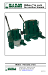
Toe Jack
Instruction Manual
Models HTJ-5, HTJ-10 and HTJ-25
12 Timber Lane • Marlboro NJ 0774 Rev. 03 08/26/2013
tel: 732.462.6277 • fax:732.462.6355
email: [email protected]
CONTENTS
1
GENERAL PRECAUTIONS
2
2.1
2.2
DESCRIPTION
IDENTIFICATION
DESCRIPTION
3
3.1
3.2
STORAGE, HANDLING, TRANSPORT
STORAGE
HANDLING, TRANSPORT
4
ASSEMBLY
5
5.1
5.2
5.3
USE
FIELD OF USE
OPERATION
SAFETY PRECAUTIONS
6
MAINTENANCE
6.1
PREVENTIVE
6.2
MALFUNCTION, FAILURES
6.3
DISASSEMBLY - ASSEMBLY
6.3.1
DISASSEMBLY
6.3.2
ASSEMBLY
6.4
MAINTENANCE LOG
7
CHECKS: STARTUP / PERIODIC
8
SCRAPPING
DIAGRAMS / PARTS LISTS
DISCHARGE VALVE
EXPLODED VIEW: PUMP
EXPLODED VIEW: 5t AND 10t TOE JACKS
EXPLODED VIEW: 25t TOE JACK
PARTS LIST
LIMITED WARRANTY
2
USER AND MAINTENANCE INSTRUCTIONS FOR
HILMAN TOE JACKS
IMPORTANT
This guide must be read and understood before using, maintaining or
repairing this jack. The plant manager and the operators must take the
following warnings seriously:
• These users and maintenance instructions concern any operator
using, maintaining and repairing a Hilman Toe Jack.
• The plant manager must make sure that the operator is aware of
all information given in the guide and ensure that this guide is
always available when the jack is being used. If the jack is sold,
used by other plant managers or operators then these
instructions must be handed over.
• It is an impossible task to list and to update all rules and
regulations in force in these instructions with regard to all user
countries concerned. Consequently, the user must obtain all
relevant information and ensure that this information is given to
operators and taken into account by them.
1- GENERAL PRECAUTIONS
• This jack can only be used by skilled, competent and trained operators.
• This jack can only be used incompliance with the instructions given in
this document. Personal injury and damage to property may occur if the
jack is not used in compliance with these instructions.
• The operator must check that the jack is in good general condition prior
to using it.
• Never use a jack on which the identification has been erased.
• The manufacturer refuses all responsibilities for any consequences
resulting from a change or a modification in the characteristics without
his written approval as well as for any repair made by third parties other
than himself or his accredited repair shops.
2- DESCRIPTION
2.1. Identification:
Year, models & series no.: stamped on the pump board.
Capacity: embossed on the tank.
3
2.2. Description
The package contains:
the jack, control handle, retaining pin & these instructions.
Capacity (Tons)
Lift (mm)
Loading height / toe (mm)
Loading height / head (mm)
Load on lever (under full load)
Weight:
Lowing speed
Use temperatures
Dimensions: (mm)
A
B
C
D
E
F
G
H
I
J
K
L
Safety Devices:
4
5T
206
25
368
38 daN
24.5 kg
Adjustable
0°C ~ +50°C
10 T
233
25
413
40 daN
34.5 kg
Adjustable
0°C ~ +50°C
25 T
233
58
470
40 daN
107 kg
Adjustable
0°C ~ +50°C
547/627
371/451
131
200
115
55
206
25
90
93
130
368/574
582/642
371/451
134
196
120
55
233
25
90
93
170
413/646
930/1115
640/825
N/A
330
226
90
233
58
90
160
270
470/703
In-plant pre-set limiter
Control handle used to immediately stop lowering
3- HANDLING, TRANSPORT, STORAGE
3.1. Storage
• Store jacks retracted in a dry place.
3.2. Handling, transport
• Jacks should only be handled using the handle provided for this
purpose. Avoid carrying jacks using the jacking lever.
• Do not drop or throw jacks. Impacting the outside of the control lever
may deform the piston making the pump unusable.
• Before transporting jacks, wedge them so as to stop them from hitting
surrounding items.
• Make sure Pressure release knob is in “Closed” position to avoid air
being drawn into hydraulic circuit.
4- ASSEMBLY
The only assembly operation required is to fit the hand tube on the pump
lever then to insert the safety pin.
5- USE
5.1. Field of use
The jacks from Hilman Rollers are designed for handling objects, lifting or
moving loads from a sufficiently resistant and stationary location (for
examples: concrete floor) using the toe or the head of the jack. The 5 and
10 Ton jacks can be used either vertically or horizontally. The 25 Ton Jack
can be used only vertically. The body can be positioned in relation to the
toe and the base so as to be able to lift objects in restricted areas. The toe
must always be located above the base so that it can fold into it when the
jack is closed (see sketch).
5.2 Operation
Lifting
• Turn the release valve knob in a clockwise direction until it is snug (i.e.
Closed Position)
• Pump by moving the jacking in a up and down motion.
• Lifting stops as soon as the jacking lever is no longer moved.
Lowering:
• Slowly loosen the release valve knob by turning it in a counter
clockwise direction (i.e. Open Position). The more the knob is loosened
the faster the load will be lowered.
• Stopping is instantaneous when the knob is tightened.
Note: When jack is not under a load, it is necessary to press on its head to lower it.
CAUTION: It is strictly forbidden to unscrew parts other than the control handle,
except during a maintenance operation.
5
5.3. Safety precautions
• Lifting loads is dangerous operation. The personnel must be skilled, trained
and experienced in this type of operation.
• Never exceed the maximum recommended limit.
• Make sure that load bearing points are resistant and stable (ground, load,
etc.) prior to carrying out any operation.
• Only work on flat surfaces.
• Always put a wedge between the floor and the load, prepare it before
starting the lifting operation.
• Make sure that the load remains stable during all lifting operations so that it
cannot slide or tip over (block travelling plant and apply brakes).
• Never use jacks to lift loads when personnel are standing on it.
• Always set up the operation so that if an unforeseen failure occurs, it does
not cause injury to the operator or damage to the environment.
• Never lift up a load with the end of the toe (or cause this situation after the
toe has been moved). The toe must be fully fitted in place and the thrust
point of the load must never be further away from the barrel than the place
where the logo is embossed on the toe.
• Do not, under any circumstances, tamper with the adjustment of the jack’s
internal relief valve screw.
• Do not add additional load to a lifted load.
• Keep clear of lifted loads.
• When lifting by the toe, wedge the head of the jack on the load to avoid
bending the column. Refer to sketch.
• Never lift up a load on the edge of the head of the jack. The load must
always cover the top to contact the hatched area shown below.
• Lifting a load with several jacks is always a difficult operation that has to be
carefully prepared and supervised. Pay special attention to the transfer of
the load during lowering and lifting operations. The total capacity of the jacks
used must be appreciable greater than the load to be lifted.
6
6- MAINTENANCE
IMPORTANT NOTE: Use only original HILMAN spare parts.
6.1. Preventive
A – Before each use
•
•
•
•
Check that all plugs and screws are tightened by hand.
Check that there are no visible signs of an oil leak.
Check that the barrel, toe and base are not deformed or cracked.
Check that the pump operates normally when not loaded.
B – Yearly
The frequency of this check should be shortened if the jack is used very
frequently.
• Check that all nuts, screws and plugs are tightened. Adjust if necessary.
• When the jack is not under load: pump up to full travel distance until the
release value operates. No signs of leaks should be found (signs of oil
on the column or the piston is normal). Release the pressure and
inspect the column for signs of impacts, scratches as well as
straightness. Replace the column if defective.
• Lower the jack by hand. Check that there are no friction points (slight
vibrations are normal.)
• Examine carefully all external parts of the jack.
Barrel: deformation, cracks, impact marks.
Pump lever: deformation, excessive clearance in pins (replace pins if
an excessive clearance is found).
Toe: deformation, cracks.
Base: deformation, cracks.
• In the event of doubt (especially regarding cracks), do not hesitate in
replacing or carrying out any pertinent inspection to check the part.
• All defective parts must be replaced and, most of all, not straightened
out, heated or welded.
• Part replacement must be in accordance with the instructions given
under disassembly-assembly (paragraph 6.3).
6.2 Malfunction, Failures
FINDINGS
The hand tube is “slack“ and
the jack does not lift the load.
The hand tube rises after each
time it is pumped.
The jack does not lift up nor
hold the load.
The hand tube is exceptionally
hard to move.
The hand tube is exceptionally
hard to move and the jack does
not lift normally.
CAUSES / TESTS
Try without load to find
out if it is the same:
Otherwise:
The check valve leaks.
The load is too high.
The relief valve is not
fully tightened.
If the fault continues
The pump piston is
twisted.
The valve is seized.
Insufficient oil in the
diaphragm.
REMEDIES
Bleed as in paragraph 6.3.2.E
Replace the diaphragm.
Retry after pumping several times
under no load. If this continues,
replace it.
Check the weight of the load, check
whether it is stuck somewhere or
hooked onto something.
Tighten it by hand, then retry.
Replace the relief valve.
Replace it.
Replace it.
Adjust the quantity of oil, refer to
paragraph 6.3.2 E.
7
6.3. Disassembly - Assembly
These operations should only be carried out by skilled mechanics trained in
the maintenance of hydraulic equipment using appropriate tooling.
6.3.1 Disassembly
Follow the instructions below in the given order to disassemble your unit fully.
A - Jack draining
a)
b)
c)
Lift the jack up and maintain the column (2) extended by putting a block
between the base and the toe (5).
Remove plug (8).
Drain oil contained in the jack body (1).
B – Pump disassembly
a)
b)
c)
d)
e)
f)
Remove spindle (19).
Remove lever assembly (14), piston (26) and link (17) from the pump.
Remove 4 screws (13).
th
Separate the pump from the tank by rotating it 1/6 of a turn, using two
M 10 screws in the tapped holes of screw (13).
Remove diaphragm (10) from the tank, drain it and wipe it with a clean
cloth. (only for 5t and 10t).
Remove protector diaphragm.
C – Column disassembly
a)
b)
c)
d)
Remove spring ring (3) using a pair of pliers. Scrap it.
Remove the column, (2) toe (5) and guide (4) assembly from complete
column (2).
Heat guide (4) (~200_C) which was fitted with glue before unscrewing it.
Remove toe (5), O-rings (6) and seals (7).
D- Pump disassembly
a)
b)
c)
d)
e)
f)
g)
h)
8
Remove valve body (24).
Remove suction valve located at the bottom of valve body (24) by
unscrewing stop screw (32). Remove filter (51) located at the bottom of
the valve body.
Remove the bleed valve located on the top part of pump barrel (22) by
consecutively unscrewing plug (33) and screw (32).
Remove check valve (48) if it has to be replaced.
Remove handle (42).
Remove snap ring (41) before unscrewing the relief valve (34).
Extract sleeve (23) using a press.
Remove seals (27), (28), (29) and (46).
E – Discharge valve disassembly:
WARNING: This operation is not be carried out if you do not have the
equipment required to calibrate the available jack.
Loosen nozzle (35) to access ball (36), shuttle (37) and spring (38).
F – Lever disassembly
Remove spindles (18) to separate lever (14) from piston (26) and link (17).
6.3.2. Assembly
Clean all parts, except the seals and the diaphragm, using a degreasing
product (e.g.: trichlorethylene) prior to reassembling the jack then carefully
dry these parts. Inspect all seals which may have been nicked during
disassembly.
A – Column Assembly
a.
b.
c.
d.
e.
f.
g.
h.
Install seals and O-rings (6) and (7) on the lifting toe (5).
Lubricate the bore in the toe (5).
Install toe (5) on column (2).
Screw guide (4) on column (2) after having carefully cleaned threading
and put a drop of strong threadlock LOCTITE on one part.
Remove away surplus of threadlock.
Lubricate the machined outer surface of the toe (5).
Fit the completed assembly inside the jack body (1).
Install spring ring (3) which, before installation, is in the shape of a
straight wire with rounded ends, curve it slightly and fit it through the
rounded part on the edge of the slot made in jack body. Hit the other
end with a hammer while maintaining it firmly with pliers.
B- Pump Assembly
a. Install seals (27), (28) and beta pin (16) on sleeve (23) then lubricate
the bore of the pump in which they are fitted.
Caution: For the stage a) use a standard grease and not a silicon grease.
b. Fit the sleeve in the pump barrel using a small hydraulic press.
c. Install the suction valve in the body of valve (24) in accordance with the
order given: ball (30), spring (31) and stop screw (32).
Caution: After the ball (30) has been fitted, hit it with a hammer using a soft
steel drift to peen its seat and provide good sealing.
d. Tighten the valve body (24) to the pump barrel (22) after having
installed O-ring (25) and filter (51) using snap ring (50).
e. Fit check valve (48) in the pump barrel (22).
f. Install the bleed valve in the pump barrel (22) in the following order:
spring (31), ball (30) then stop screw (32).
g. Fit seals (29) after having coated them with silicon grease. Also coat the
bore in the jack body in which the pump is mounted.
9
C – Relief valve assembly
a.
b.
c.
Assemble spring (38), shutter (37), ball (36) and nozzle (35).
Lubricate O-ring (40) and fit it.
Install relief valve (34) on the pump and fit snap ring (41).
D – Final Assembly of the jack (5 t and 10 t only)
a.
b.
c.
d.
e.
f.
g.
h.
i.
j.
k.
Position the jack vertically and hold the column in ½ extended position.
Fit diaphragm (10) in the tank of body (1).
Fill the diaphragm with 5 CL of oil.
Install pump assembly in its housing in the body. During this operation,
make sure to not damage seals (29). A mallet is used for this assembly
operation inserting a wooden shim on the top flat surface of the pump.
(You can also buy a special tool for the assembly.)
Tighten screws (13).
Fill the jack body (1) through the top port until the oil flows out by the
port of plug (8).
Tighten plug (8) on the related seal (9).
Fill the cavity of the piston with oil.
Fit lever assembly (grease the pins) and open discharge valve (1/4 of
turn).
Lower the jack and purge it with the bleed valve ball in using a rod.
Continue until the bubble escape by the bleed port.
Tighten plug (33) on related sealing washer (47).
D – Final Assembly of the jack (25 t only)
a.
b.
c.
d.
e.
f.
g.
h.
i.
j.
k.
Position the jack vertically and hold the column in ½ extended position.
Fill the jack body through the top port.
Tighten plug (8) on related seal (9) by the hand.
Open the discharge valve.
Lower the jack.
Remove plug (8) and fill the jack with oil. First of all remove filter Rep A
Push the bleed located under the filter Rep. A. Continue until the
bubbles escape by the bleed port.
Tighten plug (8) on related seal (9).
Fill the cavity of the piston with oil.
Fit lever assembly (grease the pins).
Lift the jack to the top (if the lever becomes “slack” or does not lift
normally restart to the stage a).
E – Testing:
Carry out the checks described in paragraph 6.1.B after assembly.
Furthermore, if the discharge valve was removed, it would be necessary to
check that the calibration of the valve did not change. For this, a load sensor
(compression) will be fitted:
• As far as possible, between the toe and a sufficiently strong enough
item.
• Otherwise between the head and sufficiently strong enough item.
10
This sensor should indicate the following values when the jack is actuated
and the discharge valve has operated:
On toe + 0, + 500 daN
On head* + - 1 000 daN
5T
5 000 daN
7 000 daN
10T
10 000 daN
13 000 daN
Calibration on the head is less significant as it depends on efficiency which
varies from one jack to another.
IF THESE VALUES ARE NOT OBTAINED:
If they are lower: the jack may be used knowing that it can lift up a smaller
load.
If they are greater: replace the discharge valve.
6.4. Maintenance Log
Reminder: The user is bound to keep a maintenance log up to date (Article
R.233-12), in order to ensure operator safety.
7. CHECKS: STARTUP / PERIODIC
These checks are mandatory in all countries in EEC. In France, decree 9341 “Users” dated 11/01/93 and law dated 9/06/93 set down the conditions.
Other texts, laws or decrees passed or to be passed since the printing of
these instructions will supersede the former mentioned
8. SCRAPPING
When a jack becomes old or when damage occurred likely to be a source of risk,
the user MUST eliminate the equipment, i.e. ensure that it cannot be used. To
this end (refer to paragraph 6.3):
• Drain the jack, paragraph 6.3.1.A
• Remove the relief valve, paragraph 6.3.1.Df.
11
DISCHARGE VALVE
Plan No. 28087
12
EXPLODED VIEW: PUMP
Plan No. 28086
13
EXPLODED VIEW: 5t AND 10t TOE JACKS
Plan No. 28635-01
14
5 & 10T HYDRAULIC JACKS PART LIST
ITEM
01
02
03
04
05
06
07
08
09
10
12
13
14
15
16
17
18
19
20
21
22
23
24
25
26
27
28
29
30
31
32
33
34
35
36
37
38
39
40
41
42
43
44
45
46
47
48
50
51
QTY
1
1
1
1
1
1
1
1
1
1
1
4
1
1
1
1
2
1
3
3
1
1
1
1
1
1
1
2
3
2
2
2
1
1
1
1
1
1
1
1
1
1
1
1
1
1
1
1
1
5T JACK
28502
28488
25618
28487
28481
60659
60160
28447
60652
26650
60494
60300
32735
26656
60174
28478
28448
26668
60029
60046
28508
28513
28511
60654
28477
60294
60582
60295
60164
27047
25627
28089
25631
27592
60169
25633
25632
60602
60660
60171
25635
60603
28517
60669
60668
60653
60651
60671
28573
10T JACK
28503
28543
25642
28504
28482
60661
60161
28447
60652
27920
60494
60300
32735
26656
60174
28478
28448
26668
60029
60046
28508
28513
28511
60654
28477
60294
60582
60295
60164
27047
25627
28089
25631
27592
60169
25633
25632
60602
60660
60171
25635
60603
28517
60669
60668
60653
60651
60671
28573
DESCRIPTION
JACK BODY
COLUMN
SPRING RING
GUIDE
TOE
O-RING
SEAL
PLUG
BS SEAL
DIAPHRAGM
EXPANDER PLUG
SCREW
LEVER
HAND TUBE
BETA PIN
LINK
SPINDLE
SPINDLE
WASHER
NUT
PUMP BARREL
SLEEVE
VALVE BODY
O-RING
PISTON
SEAL
SEAL
SEAL
BALL
SPRING
STOP SCREW
PLUG
RELIEF VALVE
NOZZLE
BALL
SHUTTER
SPRING
SCREW
O-RING
SNAP RING
KNOB
SCREW
WASHER
SCREW
SEAL
SEALING WASHER
CHECK VALVE
SNAP RING
FILTER
15
Exploded View: 25t Toe Jack
Plan No. 28790-06
16
25 TON HYDRAULIC JACKS PART LIST
ITEM
QTY
25T JACK
DESCRIPTION
ITEM
QTY
25T JACK
DESCRIPTION
01
02
1
1
28791
26638
BODY
COLUMN
03
04
05
06
1
1
1
1
28802
28803
28789
60705
SPRING RING
GUIDE
TOE
O-RING
42
43
44
45
1
1
1
1
25635
60603
28517
60669
KNOB
SCREW
WASHER
SCREW
07
08
09
12
1
1
1
1
60666
28447
60652
60494
1
1
1
1
60663
60651
60671
28573
SEAL
VALVE
SNAP RING
FILTER
13
14
15
4
1
1
60300
28480
28814
55
56
58
59
60
61
1
2
2
1
2
2
60225
60838
28084
28085
26649
28809
SNAP RING
SCREW
SMALL LINK
SPINDLE
RAIL WHEEL
SHAFT
16
17
18
1
1
2
60174
28808
28448
SEAL
PLUG
BS SEAL
EXPANDER
PLUG
SCREW
LEVER
HANDLING
TUBE
BETA PIN
SMALL ROD
SHAFT
46
48
50
51
19
20
21
22
1
3
3
1
26668
60029
60046
28508
2
2
1
1
60226
26648
30111
30112
67
1
30609
SNAP RING
WASHER
NOZZLE
FILTER
SUPPORT
PIPE
23
24
25
26
1
1
1
1
28800
28511
60654
28801
SHAFT
WASHER
NUT
PUMP
BARREL
SLEEVE
VALVE BODY
O-RING
PISTON
62
63
65
66
27
28
29
30
1
1
2
3
60294
60662
60295
60164
SEAL
SEAL
SEAL
BALL
31
32
33
34
35
3
2
2
1
1
27047
25627
30607
25631
27592
SPRING
STOP SCREW
SHUTTLE
RELIEF VALVE
NOZZLE
36
37
38
39
1
1
1
1
60169
25633
25632
60602
BALL
SHUTTER
SPRING
SCREW
40
41
1
1
60660
60171
O-RING
SNAP RING
17
LIMITED WARRANTY
We warrant each new Hilman Toe Jack sold by us to be free from
manufacturing defects in normal service for a period of one (1) year
commencing with delivery of the Toe Jack to the original user. Our
obligation under this warranty is expressly limited at our option, to
the replacement or repair at Hilman, Incorporated, Marlboro, New
Jersey 07746 USA, or at a service facility designated by us, of such
part or parts as inspection shall disclose to have been defective. This
warranty does not apply to defects caused by damage or unreasonable
use, including failure to provide reasonable and necessary
maintenance while in the possession of the consumer.
WE SHALL NOT BE LIABLE FOR CONSEQUENTIAL
DAMAGES OF ANY KIND, including, but not limited to,
consequential labor costs or transportation charges in connection with
the replacement or repair of defective parts. We make no warranty
with respect to trade accessories. They are subject to the warranties
of their manufacturers.
ANY IMPLIED OR STATUTORY WARRANTIES, INCLUDING
ANY WARRANTY OF MERCHANTABILITY OR FITNESS FOR
A PARTICULAR PURPOSE, ARE EXPRESSLY LIMITED TO
THE DURATION OF THIS WRITTEN WARRANTY. We make no
other express warranty, nor is anyone authorized to make any on our
behalf.
*In compliance with 1975 Consumer Product Warranties Law
HILMAN, INCORPORATED, 12 Timber Lane, Marlboro, New
Jersey 07746
18
HILMAN SERVICE BULLETIN – HTJ-25 TOE JACK
NOTE: Do not lift the jack unless the release valve is fully closed.
Lifting the jack with the release valve open will cause air to be
sucked into the jack’s hydraulic system causing faulty operation.
AIR PURGING PROCESS
Use the following steps to bleed air from the jack in the event it
has been accidentally lifted with the release valve open.
A)
B)
C)
D)
E)
F)
Close the release valve.
Pump the jack to full extension without a load.
Loosen the plug (1 1/16 socket) on the head of the jack.
Allow air to bleed out until hydraulic oil starts to flow.
Re-tighten the fill plug.
Check the jack for proper operation.
19
Toe Jack
Inspection Certificate
Capacity / Model Number:
____________________
Serial Number:
___________
Manuf. Date:
_________
Inspected by: ___________________________________
Inspection Date:
____________
Inspector’s Signature:
______________________
Approval Stamp:
Models HTJ-5, HTJ-10 and HTJ-25
12 Timber Lane • Marlboro NJ 07746
tel: 732.462.6277 • fax:732.462.6355
email: [email protected]
Rev. 03 08/26/2013