1
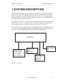
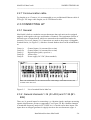
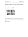
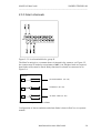
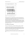
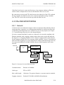
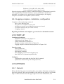
MasCon 48
On-line system for continuous monitoring
Part No. 32086800
Revision A
User Manual
Copyright © 2007 by SKF Reliability Systems
All rights reserved.
Aurorum 30, 977 75 Lulea
Sweden
Telephone: +46 (0) 920 75850, Fax: +46 (0)920 13440
MANUAL MasCon48
NÅIDEN TEKNIK AB
____________________________________________________________________
CONTENTS
CONTENTS............................................................................................................... I
1 SYSTEM DESCRIPTION................................................................................. 1:1
2 INSTALLATION DIRECTIONS MASCON48 .............................................. 2:1
2.1 INSTALLATION.......................................................................................... 2:2
2.1.1 Sensor installation (Accelerometer type PCB 327, 601) ....................... 2:2
2.1.2 Sensor installation (Displacement sensor, inductive-non-contact) ....... 2:3
2.1.3 Sensor installation (Pulse transmitter, inductive-non-contact) ............. 2:3
2.1.4 MasCon - mounting................................................................................ 2:3
2.2 CABLES ....................................................................................................... 2:4
2.2.1 Cable routing ......................................................................................... 2:4
2.2.2 Sensor cable - vibration ......................................................................... 2:5
2.2.3 Sensor cable - Others............................................................................. 2:5
2.2.4 Supply cable ........................................................................................... 2:5
2.2.5 Junction box ........................................................................................... 2:5
2.2.6 Cable fittings .......................................................................................... 2:5
2.2.7 Communication cable ............................................................................ 2:6
2.3 CONNECTING UP....................................................................................... 2:6
2.3.1 General................................................................................................... 2:6
2.3.2 General channels 1-16 (A1-A32) and 17-32 (B1-B32) .......................... 2:6
2.3.3 Alarm channels ...................................................................................... 2:8
2.3.4 Speed channels (C1 – C16) .................................................................... 2:9
2.3.5 Data communication .............................................................................. 2:9
2.4 ON-LINE MONITORING.......................................................................... 2:10
2.4.1 General................................................................................................. 2:10
2.4.2 Logging computer– installation, configuration ................................... 2:11
2.5 START-UP.................................................................................................. 2:11
2.6 SETTINGS.................................................................................................. 2:11
2.6.1 General................................................................................................. 2:11
2.6.2 Settings - Motherboard ........................................................................ 2:12
2.6.3 Unit number (default = Nr:1) .............................................................. 2:12
2.6.4 Settings - Module board....................................................................... 2:13
3 MASCON UNIT ................................................................................................. 3:1
3.1 DESCRIPTION OF THE MASCON UNIT .............................................................. 3:1
3.2 USAGE OF THE MASCON UNIT ........................................................................ 3:1
4 TROUBLESHOOTING GUIDE ...................................................................... 4:1
4.1 POSSIBLE FAULT TYPES ......................................................................... 4:1
4.1.1 Sensor signal disappears or is abnormally changed (single channels). 4:1
4.1.2 A sensor repeatedly generates a false alarm or varies abnormally ...... 4:2
4.1.3 Speed signal unobtainable/ faulty for a certain machine ...................... 4:2
4.1.4 Analogue input gives faulty/ no signal................................................... 4:2
4.1.5 Load input gives faulty/ no input signal................................................. 4:3
Contents
i
MANUAL MasCon48
NÅIDEN TEKNIK AB
____________________________________________________________________
4.1.6 MasCon’s alarm relay does not activate despite warning alarm .......... 4:3
4.1.7 Logging completely ceases to function .................................................. 4:3
4.1.8 Logging ceases to work from a certain MasCon unit ............................ 4:3
4.2 CHECK OF SENSOR AND SENSOR CABLING FOR VIBRATION CHANNELS............ 4:4
4.3 CHECK OF SENSOR AND SENSOR CABLING FOR ANALOGUE CHANNELS: ..... 4:6
4.4 CHECK OF SPEED INPUT: ........................................................................ 4:7
4.5 CHECK OF RELAY SIGNAL: .................................................................... 4:7
4.6 LOGGING PROBLEMS: ............................................................................. 4:8
5 TECHNICAL DATA MASCON48® ................................................................ 5:1
Contents
ii
MANUAL MasCon48
NÅIDEN TEKNIK AB
____________________________________________________________________
1 SYSTEM DESCRIPTION
MasCon units are linked in a network that is connected via a modem to a logging
computer (ProCon). The logging computer in turn can be connected to e.g. a LAN
network. Several ProCon clients may be linked in this network. Through a general
interface ODBC it is possible to link the logging computer to an existing database for
an existing control or processing system.
Each MasCon unit features 5 relay outputs to be used to handle alarms, warnings and
system errors. There are 32 general inputs for vibration signals or analogue inputs
and 16 digital inputs, for example for speed measurement. See Figure 1:1.
It is possible to link 16 relay outputs to the logging computer by equipping it with a
relay card. When the logging computer is used to handle Alarms and Warnings it is
possible to control single machines that are linked to the MasCon unit.
MasCon
32 General inputs
FFT analysis, DPE,
DC measurements, etc.
ICP , 0-5 V alt.
0-10 V , 4-20 mA
16 Digital inputs
(pulse)
Optoisolated
Max 24 Volt
Communication
Ethernet 10/100
Mbit.
5 Relay outputs
System error (1)
Warning (4)
Alarm (2)
Figure 1:1 MasCon
System description
1:1
MANUAL MasCon48
NÅIDEN TEKNIK AB
____________________________________________________________________
LOGG PC (ProCon)
ODBC
LAN
Ethernet, TR
ODBC
ProCon
Coax, Fibre,
WLAN or TP
Process
Control
16 Relay outputs
SWITCH
MasCon
MasCon
MasCon
MasCon
MasCon
Figure 1:2 MasCon units in a network
System description
1:2
MANUAL MasCon48
NÅIDEN TEKNIK AB
____________________________________________________________________
2 INSTALLATION DIRECTIONS
MasCon48
Figure 2:1 MasCon48
(Guidance in installation and connection of systems
for condition monitoring using MasCon)
IMPORTANT !!
( In cases where Nåiden Teknik AB does not have direct responsibility for
the assembly and connection of a MasCon system )
Nåiden Teknik AB expects that installation of a MasCon system is carried out in
accordance with the instructions and advice given in this manual.
Any departure from these directions may be made only in consultation with
personnel from Nåiden Teknik. In other cases, the installation will not be approved
and start-up of the system will not be carried out until the errors are rectified.
Installation errors that Nåiden personnel are required to rectify when the system is to
be started up will be debited.
Therefore, please contact Nåiden at the slightest doubt during installation of your
MasCon system.
Installation directions MasCon48
2:1
MANUAL MasCon48
NÅIDEN TEKNIK AB
____________________________________________________________________
2.1 INSTALLATION
2.1.1 Sensor installation (Accelerometer type PCB 327,
601)
The basic pre-condition for a successful measurement result is that the sensor is
correctly located with regard to vibration factors.
1. Select a location for the sensor where it will not be exposed to mechanical
impact and unnecessary radiant heat. If the sensor nevertheless is given an
exposed location, some form of protective cover must be mounted over the
sensor.
2. Prepare the surface where the sensor is to be fitted. Paint, rust or other coatings
must be removed in order that the sensor shall make good contact with the
surface. In order that the area of contact shall be as large as possible, the
surface must be flat.
3. Drill a hole perpendicular to the surface with a 5 mm bit (depth c. 10 mm).
4. Thread the hole with an M6 threading tap.
5. Carefully test-screw the sensor in place, to ensure that good contact is made.
If the sensor does not fit flat on the surface, and thereby makes
bad contact with it - Drill a new hole!!
6. Unscrew the sensor and apply some form of threadlock on the contact surface
and mounting screw, e.g. LOCTITE 242.
7. Tighten the sensor with a torque wrench. It is important that the sensor is
tightened to the correct torque, to avoid the occurrence of false vibrations.
Tightening too hard, besides damaging the thread, causes stress that causes
vibrations. The correct tightening torque is: 3-7 Nm.
Installation directions MasCon48
2:2
MANUAL MasCon48
NÅIDEN TEKNIK AB
____________________________________________________________________
2.1.2 Sensor installation (Displacement sensor, inductivenon-contact)
NB! A displacement sensor always measures the distance between the sensor
and the measurement object. This means that an inadequate reference (unstable
sensor mounting) gives a displacement indication that is not based on the
measurement object.
An unstable reference can be due to:
- Too weak mounting
- Too long mounting (sensitive to temperature gradients)
- Lack of a stable fundament for sensor mounting.
We recommend use of Nåiden’s sensor mounting 1419.
Adjust the distance between the sensor and measurement object to half the
measurement range (see sensor data sheet).
Example: A sensor with measurement range 0-10 mm and output signal 4-20 mA, is
adjusted approximately with a feeler gauge to 5 mm. An exact adjustment is then
performed to 12 mA.
2.1.3 Sensor installation (Pulse transmitter, inductive-noncontact)
A pulse transmitter, linked to MasCon, is used to measure rotational speed e.g. of a
shaft. In order for the inductive sensor to register pulses, there must be one or more
distinct projections on the shaft. Each time a projection passes the sensor, a
measurement pulse is generated. The measurement projection can be an existing
spline or bolt (M6-M8). The distance between sensor and projection is adjusted to 24 mm. When configuring (ProCon), the number of pulses indicated per revolution is
specified (number of projections).
2.1.4 MasCon - mounting
-
The MasCon unit is mounted at a location where it is not exposed to
unnecessary radiant heat or strong magnetic fields.
-
Ambient temperature
-
The unit should be mounted near the measurement object so that the sensor
cable is as short as possible.
-
It is important also that MasCon is mounted at a height that permits easy
viewing of the display
-10 to +40 °C
-20 to +50 °C
Installation directions MasCon48
(normally)
(momentarily)
2:3
MANUAL MasCon48
NÅIDEN TEKNIK AB
____________________________________________________________________
2.2 CABLES
2.2.1 Cable routing
The cable should be as short as possible, since long cables impair frequency
properties and expose the system to external interference
(long cable: > 50 m).
When routing a sensor cable it is important that the cable is firmly fixed. The cable
may never be allowed to vibrate or oscillate, since this affects the capacitance of the
cable and thereby the measurement result.
The sensor cable may not be routed or bundled together with supply cables, which
generate strong magnetic fields, such as supplies to: motor drives, radiators,
electronic frequency converters, ovens etc.
It is permissible to reduce the amount of cable by using multiple conductors.
In order to facilitate servicing and maintenance it is advantageous to mount junction
boxes close to each measurement point. This is a requirement, in cases where sensors
with fixed cables are used.
An example of the above is shown in Figure 2:2
Approx. 50 m
1*2*0.5
Junction
box
3*2*0.5
MasCon No: 1
Sensor
MasCon No: 2
S-FTP
Log computer
Ethernet Switch
Figure 2:2 Cable routing to MasCon
Installation directions MasCon48
2:4
MANUAL MasCon48
NÅIDEN TEKNIK AB
____________________________________________________________________
2.2.2 Sensor cable - vibration
A shielded, twisted pair cable is used for the vibration sensor.
Remember also to select a cable that is suited to the environment in which it is to be
located (temperature, water, oil.....)
Recommendations:
- Twisted pair cable
- Area 0.5 mm2
- Shielded (common copper braid)
- Multicore conductors (gives flexible cable)
- The outer sheath must withstand the environment (heat, cold, humidity,
chemicals....)
It is also permissible to use coaxial cable, but this is more troublesome to handle
during installation
Example:
LiYCY
DUE 4001
1 x 2 x 0.5
1 x 2 x 0.5
Twisted pair
Twisted pair
2.2.3 Sensor cable - Others
To connect other sensors to MasCon, such as e.g. speed sensor, displacement sensor,
pressure sensor, data communication RS 485, etc., use:
-
Shielded, twisted pair 2*2* 0.5
FKAR-PG 2*2* 0.50, DUE 4002 or corresponding
2.2.4 Supply cable
To connect MasCon to 220 V, use:
FKLK 3*1.5 or
EKLK 3*1.5 or corresponding
2.2.5 Junction box
E 14 395 02 or similar
2.2.6 Cable fittings
Metallic EMC type cable fittings are used for all cable lead-throughs except the
communication cable.
Installation directions MasCon48
2:5
MANUAL MasCon48
NÅIDEN TEKNIK AB
____________________________________________________________________
2.2.7 Communication cable
For lengths up to 15 metres, it is recommended to use prefabricated Ethernet cable of
FTP type. For longer cable lengths, use S-FTP Ethernet cable.
2.3 CONNECTING UP
2.3.1 General
MasCon48 is built to a modular concept that means that each unit can be equipped
uniquely with regard to the type and number of channels. The equipment consists of
different types of input boards, which are mounted on the motherboard under the
protective cover (see chapter 2.6). Connections are made to the groups of pluggable
terminal blocks, see Figure 2:3, which are located furthest down on the motherboard
as:
Group A:
Group B:
Group C:
Group D:
Group E:
A
General inputs, 16 (mounted 8 at a time)
General inputs, 16 (mounted 8 at a time)
Digital inputs (pulse, speed etc.)
Alarm relays
Power supply 24 V DC (Non-standard).
B
C
D
Note! All cableshields is to be connected to the cable fittings of the MasCon unit, and
isolated in the other end.
Figure 2:3
List of terminal blocks MasCon
2.3.2 General channels 1-16 (A1-A32) and 17-32 (B1B32)
There are 16 general inputs for connecting e.g. vibration signals, analogue measuring
signals (displacement, pressure, temperature), see Figure 2:4. By vibration channels
is meant that frequency analysis (FFT, DPE, etc.) is carried out on these inputs. The
inputs have an integral generator to supply current to the accelerometers (appr. 4
Installation directions MasCon48
2:6
MANUAL MasCon48
NÅIDEN TEKNIK AB
____________________________________________________________________
mA). If a sensor that does not require any current is to be connected, then the
configuration of the input board must be changed, through the DIP switch setting
(see Chapter 2.6).
A (B)
Figure 2:4 List of terminal blocks, group A and B
If current signals (4-20 mA) are to be connected, resistance (220 ohm) must be
connected to the input board. This is done using the DIP switch on the analogue
cards and with an external resistance of 250 ohm on the vibrationcards. (see Chapter
2.6).
When wishing to connect signals from other equipment – use the input board with an
insulation amplifier.
Installation directions MasCon48
2:7
MANUAL MasCon48
NÅIDEN TEKNIK AB
____________________________________________________________________
2.3.3 Alarm channels
D
Figure 2:5 List of terminal blocks, group D
The MasCon unit gives a common alarm via internal relay contacts, see Figure 2:5.
the contacts may be loaded to a maximum of 48 V, 1A. If higher loads are required,
then further relays must be fitted. Relay functions for alarms are connected as in
Figure 2:6.
MasCon
SYSTEM ERROR (D5–D6)
WARNING (D3–D4)
ALARM / TRIP (D1–D2)
Figure 2:6 Relay functions for alarms
Configuration of alarm conditions and alarm limits is done in ProCon, see separate
manual.
Installation directions MasCon48
2:8
MANUAL MasCon48
NÅIDEN TEKNIK AB
____________________________________________________________________
2.3.4 Speed channels (C1 – C16)
C
Figure 2:7 List of terminal blocks, group C
MasCon48 contains up to 16 digital inputs to be used for speed measurements, etc.
Two digital inputs are located on the motherboard (channel 1 and 2) and 14 inputs
are located on an optional digital board, see Figure 2:7. All 16 digital inputs can also
be used for alarm level control, as well as parameter gating.
Using straps, the MasCon unit is configured for external or internal power supply of
sensor. Channel 1 and 2 are configured on the motherboard and channel 3-16 on the
input board, see chapter 2.6.3.1 and chapter 2.6.4.4. The internal power supply is set
to 24 V DC. When using certain sensors with negative pulse output the connection to
terminal may need to be reversed. To our standard speed sensor, 1416, internal
power supply is to be used.
2.3.5 Data communication
MasCon unit communications are compliant with Ethernet standard 10/100Mbit.
Connecting up of the MasCon48 unit is done with a shielded modular jack. The
modular jack includes a mount box and a crimpable modular connector, where the 8
poles are coloured according to the standard. The external communication-cable, of
type S-FTP, is connected to the connector as the mounting directions provides. The
modular jack is placed on the right wall, inside the coating.
The modular jack is connected to the right side of the CPU-card by a 0.5 metre long
patch-cable of type FTP. The CPU-card is the card on the top inside the MasCon
unit.
Installationsanvisning MasCon48
2:9
MANUAL MasCon48
NÅIDEN TEKNIK AB
____________________________________________________________________
If the MasCon48 unit is connected directly to a log computer without an Ethernetswitch or hub, an adapter that crossover the Ethernet-cable is to be used.
By connecting a crossovered FTP-cable between the right side of the CPU-card and
the log computer, the MasCon unit can be connected up without using a modular
jack. The CPU-card is the card on the top inside the MasCon unit.
2.4 ON-LINE MONITORING
2.4.1 General
A MasCon unit is an industrial computer which can function independently without
connecting other computers. As an independent unit MasCon cannot store data, but
is limited to generating alarms at set vibration levels via relay outputs (see Chapter
2.3.3) and showing current levels on the integral display.
It is more common that MasCon units are connected via a network compliant with
Ethernet standard, with a logging computer where data can be stored and analysed,
See Figure 2:8. A logging computer is a PC which is equipped with a network card.
On the logging computer there are programs which regularly ”log out” from MasCon
And store data (Logging), as well as programs for analysis and monitoring (ProCon).
In a system including several MasCon units, they are linked together in the same
network.
Network
Phone modem
PC
Switch
MasCon 1
MasCon 3
MasCon 2
MasCon 4
Figure 2:8 System of several MasCon units
Communications:
Ethernet 10/100Mbit
Cable type:
FTP or S-FTP
Max. cable length:
100 metres. For greater distances, a repeater must be attached.
Logging computer:
Pentium II 350 MHz, 64 Mb RAM (minimum)
Installation directions MasCon48
2:10
MANUAL MasCon48
NÅIDEN TEKNIK AB
____________________________________________________________________
Windows 95, 98, ME, NT4, 2000 or XP.
1 free serial port if remote control is used.
Since the logging computer is always connected to MasCon it should not be used for
other purposes. Recommended location is a space prohibited to unauthorised
personnel. To facilitate service and to help in vibration analysis, the logging
computer is located near a telephone (remote control).
2.4.2 Logging computer– installation, configuration
Complete on-line monitoring consists of:
- One or more MasCon units
- One Ethernet 10/100Mbit network card.
- An Ethernet switch if several MasCon units are to be used.
- A telephone modem (only for remote control)
- A logging computer
Regarding installation and configurer, go to the ProCon Installation manual.
2.5 START-UP
Conditions (check that):
- Installation carried out as in Chapter 2.1
- Cable routed as in Chapter 2.2.1
- Cables connected as in Chapter 2.2
- Hardware settings carried out as in Chapter 2.6
- Logging computer connected and prepared as in Chapter 2.4.2
Start the system:
- Power-on MasCon
- Attach Ethernet switch
- Start logging computer
- Start "Logging” (c:\procon\exe\loggning.exe)
- Start ”ProCon” (c:\procon\exe\procon.exe)
Configure:
- Configure the system with the aid of the ProCon manual
- Synchronise measurement point settings (ProCon)
2.6 SETTINGS
2.6.1 General
Before the MasCon system is started up there are a number of hardware settings that
need to be checked. This is the unit number of the MasCon unit, which is set with the
help of a DIP switch located in the upper right corner of the motherboard, and
Installation directions MasCon48
2:11
MANUAL MasCon48
NÅIDEN TEKNIK AB
____________________________________________________________________
settings for Digital inputs 1 and 2 which are carried out with the help of straps on the
motherboard.
In order to access the switches in MasCon, the protective cover must be removed.
NB! Before removing the protective cover the MasCon must be without voltage.
Then loosen 4 screws, one in each corner. Carefully remove the cover and detach 2
ribbon cable connectors in the upper left corner, and any ribbon cable in the upper
right corner.
2.6.2 Settings - Motherboard
Figure 2:9 Location DIP switches MasCon unit
2.6.3 Unit number (default = Nr:1)
Switch U85 is used to determine which identity (no.) the unit will have. Settings are
binary
i.e. 1000=No:1, 0100=No:2, 1100=No:3 ….
(1 = ON)
2.6.3.1 Pulse input/ speed (default = ”Internal power supply”)
On the motherboard there are 2 pulse inputs (Digital 1, 2). For further pulse inputs,
refer to: ”Module card DIG”. The pulse inputs are configured with the aid of straps
located at the upper right corner of the motherboard, as in Figure 2:10 and Figure
2:11.
Installation directions MasCon48
2:12
MANUAL MasCon48
NÅIDEN TEKNIK AB
____________________________________________________________________
INTERNAL
RPM 2
RPM 1
RPM
Figure 2:10 Configuration of pulse inputs for internal power supply, i.e. MasCon
supplies the sensor with 24V DC
EXTERNAL
RPM 2
RPM 1
RPM
Figure 2:11 Configuration of pulse inputs for external supply
2.6.4 Settings - Module board
2.6.4.1 Module board VIB (default DIP1=11111111
DIP2=00000000)
A ll in o p en s ta te (O F F )
1
D IP 2
8
J2
J1
1
D IP 1
8
A ll in C lo s ed s ta te (O N )
Figure 2:12 Module card, vibration signals
Installation directions MasCon48
2:13
MANUAL MasCon48
NÅIDEN TEKNIK AB
____________________________________________________________________
A module card for vibration signals (FFT) can be mounted in module position 1
(chan.1-8), module position 2 (chan. 9-16), module position 3 (chan. 17-24) and
module position 4 (chan. 25-32).
-
Using DIP1, current supply ICP (4 mA) can be engaged or disengaged
specifically for each channel.(ON = current supply)
-
Using DIP2 the user can select ”Single Ended” or ”Differential”.(ON =
Differential).
2.6.4.2 Module card ANA (default: DIP1=00000000
DIP2=11111111)
-3107-0009 Short jumper RM 2.54
All in open state (OFF)
1
1
2
4
6
8
DIP2
J2
U9-16
J1
DCDC 1-8
DIP1
Component side
1
1
2
4
6
8
All in open state (ON)
-3107-0012 Short jumper RM 5.08
Figure 2:13 Module card, analogue signals
A module card for analogue process signals can be mounted in any module space 1
(chan. 1-8) 2 (chan. 9-16) 3 (chan. 17-24) and module space 4 (chan. 25-32).
-
Using DIP1, the current shunt (4-20 mA) can be engaged or disengaged
specifically for each channel. (ON = current shunt)
-
Using DIP2 the user can select ”Single Ended” or ”Differential”. (ON =
Differential).
Installation directions MasCon48
2:14
MANUAL MasCon48
NÅIDEN TEKNIK AB
____________________________________________________________________
2.6.4.3 Module card ANA-ISO (default: B1=00000000)
A ll in o p e n s ta te (O F F )
1
J2
U 1 -8
J1
S1
8
C o m po n e n t s id e
Figure 2:14 Module card, analogue insulated signals
A module card for galvanic insulated analogue process signals can be mounted in
module space 1, 2, 3 or 4 (chan.1-32) .
-
Using B1, the current shunt (4-20 mA) can be engaged or disengaged
specifically for each channel. (ON = current shunt)
2.6.4.4 Module card DIG (default: D-E)
-3109-0010 Pin Strip, 3 pin (J3-16)
A
B
C
-3109-0009 Pin Strip, 2 pin (J17-30)
-3109-0011 Short Jumper (J17-30)
D E
8
J2
9
10
7
6
3
5
J1
4
Figure 2:15 Module card, pulse input/speed
Installation directions MasCon48
2:15
MANUAL MasCon48
NÅIDEN TEKNIK AB
____________________________________________________________________
A module card for pulse input/speed can be mounted in module space 5 (chan.2-10).
Channel 1-2 are configured on the motherboard as in Chapter 2.6.3.1.
»
Using short circuit straps as in Figure 2:15 the sensor supply can be engaged
or disengaged specifically for each channel.
- D-E
Internal supply (MasCon supplies voltage to the sensor at 24
V DC)
- B-C
External supply
Installation directions MasCon48
2:16
MANUAL MasCon48
NÅIDEN TEKNIK AB
____________________________________________________________________
3 MASCON UNIT
3.1 Description of the MasCon unit
MasCon is a modern industrial computer designed for continuous vibration
monitoring. MasCon is highly environmentally resilient, IP 66, and is specially
adapted for machines where damage develops rapidly and where periodical
monitoring is difficult to carry out.
Up to 32 vibration sensors can be connected to each MasCon unit. MasCon can also
be connected to digital sensors or other units via one of the 16 digital inputs/ 5 relay
outputs.
Initiating MasCon is simple to carry out. This is done via an initiating program, for
example using a portable computer. All initiation parameters are saved in a separate
memory with independent current supply in MasCon. These then are retained in the
event of a loss of voltage, so that MasCon can start automatically when voltage
returns. To avoid problems with the power supply when starting up, (if several large
electrical machines are started simultaneously then powerful surges often occur on
the mains supply), the start-up routine is delayed by about one minute from the
moment when voltage is switched on.
Communication with the MasCon units complies with Ethernet standard.
3.2 Usage of the MasCon unit
MasCon is divided into modules. In its basic version, MasCon is supplied with an
input module for vibration sensor and two inputs for pulse sensors. MasCon can be
supplemented with modules for:
- Additional vibration inputs
- Analogue process signals
- Additional digital inputs
On the front panel of the computer unit there are LED diodes for the following
messages:
»
System
Lit up if an internal error has occurred, and
automatically causes MasCon to re-start.
»
5, 15, -15 V
Lit up if internal power feed is OK.
»
Relay 1-4
Lit up if each relay is activated.
MasCon unit
3:1
MANUAL MasCon48
NÅIDEN TEKNIK AB
____________________________________________________________________
4 Troubleshooting guide
This document is intended as an aid when the MasCon system is not functioning
correctly.
The document is designed for instrumentation engineers and others with sufficient
knowledge of electrical troubleshooting in electronic systems with a 230V power
supply and of the risks that this can mean in case of incorrect procedure.
Nåiden Teknik strives to provide information that is as accurate as possible. Nåiden
Teknik however cannot be held responsible for any injury or damage (to persons or
material) that can occur in the interpretation of, or due to actions taken on the basis
of information in this document.
Proximitor™ and Velomitor™ are registered trademarks of the Bentley Nevada
Corporation.
Troubleshooting is aimed to determine which of the following categories the fault
belongs to:
1.
2.
3.
4.
5.
6.
Sensor fault
Cabling fault
Hardware fault in MasCon unit
PC fault
Configuration error in software
Usage error /misconception
Note that the guarantee becomes void if MasCon units are damaged through
incorrect intervention in the hardware, or a patently incorrect connection in
contravention of directions given.
4.1 POSSIBLE FAULT TYPES
4.1.1 Sensor signal disappears or is abnormally changed
(single channels)
a/ Break in sensor cable
b/ Short circuit in sensor cable
c/ Sensor fault
d/ Hardware fault - MasCon input stage
=> Carry out sensor/ cable test as in item 2
Troubleshooting guide
4:1
MANUAL MasCon48
NÅIDEN TEKNIK AB
____________________________________________________________________
4.1.2 A sensor repeatedly generates a false alarm or
varies abnormally
a/ Break in sensor cable/ contact
b/ Incorrectly mounted sensor
c/ Hardware fault MasCon input stage
=> First carry out sensor/ cable test as in item 2. Check also the sensor mounting. If
this is without result, contact Nåiden Teknik.
4.1.3 Speed signal unobtainable/ faulty for a certain
machine
a/ Cable fault (short circuit/ break) to speed sensor
b/ Faulty speed sensor, or faulty installation
c/ Speed signal too weak/ impedance too high for MasCon
d/ Faulty MasCon speed input
e/ Incorrect settingin hardware
=> Test speed input as in item 4
4.1.4 Analogue input gives faulty/ no signal
a/ Cable fault (short circuit/ break) to sensor
b/ Faulty sensor
c/ Faulty earthing
d/ Faulty MasCon input
e/ Incorrect setting in hardware
=> First carry out control of sensor and cabling as in item 3
Troubleshooting guide
4:2
MANUAL MasCon48
NÅIDEN TEKNIK AB
____________________________________________________________________
4.1.5 Load input gives faulty/ no input signal
a/ Cable fault (short circuit/ break) to sensor
b/ Faulty sensor signal
c/ Faulty earthing
d/ Faulty MasCon load input
e/ Incorrect setting in software
=> The load input acts as an analogue input. Therefore, first carry out cabling/ input
test as in item 3 . Contact Nåiden Teknik if this gives no result.
4.1.6 MasCon’s alarm relay does not activate despite
warning alarm
a/ Cabling fault from MasCon to alarm panel
b/ Configuration error in software
c/ Hardware fault in MasCon unit
=> Follow the control schedule as in item 5.
4.1.7 Logging completely ceases to function
a/ Logging PC non-functional
b/ Logging software incorrectly set
c/ Ethernet switch non-functional
d/ Cable break in Ethernet network
=> First carry out checks as in item 6.
4.1.8 Logging ceases to work from a certain MasCon unit
a/ Loss of voltage MasCon unit
b/ Hardware fault (power supply or processor module) MasCon unit
c/ Break in RS485 bus
Troubleshooting guide
4:3
MANUAL MasCon48
NÅIDEN TEKNIK AB
____________________________________________________________________
4.2 Check of sensor and sensor cabling for
vibration channels
1. Determine the unit number and channel number of the channel in question
(through the measurement point information in the software, or through the list
of terminal blocks)
2. Measure the DC voltage between the sensor wire on the MasCon terminal
block using a digital voltmeter. See Table 4.1 for normal voltage values with
and without a connected sensor respectively.
Sensor type
Normal operating (bias)
voltage
Open-circuit voltage
DC V
DC V
Standard (type 327)
c. 8 .. 12V
+15 V
Velomitor™
c. -12V
-24 V
Proximitor™
-1 .. -17V (DC measuring)
-24 V
Table 4.1 Normal voltage values
3. Is the voltage within the normal working range?
NO:
Continue to item 5
YES:
The cabling to the sensor is probably OK and the sensor electronics have
normal input impedance. If the sensor signal is still not perceived to be
normal, one should try changing the sensor.
4. Does the fault remain after changing the sensor?
NO:
Sensor fault. The sensor is defective and must be replaced.
YES:
The fault may be in the analogue input section of the MasCon unit.
Contact Nåiden Teknik for service/ further information.
5. Is the voltage close to zero (typical < ± 0.5 V) ?
NO:
Continue to item 10
YES:
There is probably a short-circuit in the cable, or the sensor is defective.
First verify that the voltage rises to normal open-circuit voltage when one
of the sensor cable poles is disconnected from the terminal block of the
MasCon unit.
6. Did the voltage rise to normal open-circuit voltage?
YES:
Continue to item 9
NO:
The sensor is not receiving power; continue below.
7. Is it a Velomitor™ or Proximitor™ sensor?
NO:
Go to item 8
Troubleshooting guide
4:4
MANUAL MasCon48
NÅIDEN TEKNIK AB
____________________________________________________________________
YES:
These are powered by an external 24V power pack. Therefore, check the
output voltage from this unit power pack. the fault is probable in the
voltage unit or in the cabling to the MasCon terminal block. However, if
this turns out to be OK, then the MasCon input is damaged. Contact
Nåiden Teknik for further information.
8. Sensor of standard type (type 327):
These are powered internally from the MasCon unit. If the MasCon unit
does not supply open-circuit voltage with input open, then the MasCon
input is probably damaged, or the input is not configured to supply a
power feed to the sensor. Contact Nåiden Teknik.
9. The fault is in the sensor cable or the sensor. Go out to the sensor position and
disconnect the cable at this end. Reconnect the cable on the MasCon terminal
block and again measure the voltage over these two poles. Does the shortcircuit remain?
YES:
The sensor cable (or contact) has a short-circuit. Repair the cabling.
NO:
The sensor is defective. Replace the sensor.
10. Is the voltage close to the open-circuit voltage?
NO:
If the voltage appears to be neither within the normal working range,
close to zero nor close to open-circuit voltage, then the fault is an
unusual one. First check that the measurement was correctly carried out,
then contact Nåiden Teknik. Remaining faults can be due to a damaged
sensor or a damaged MasCon input. First disconnect one pole of the
sensor cable and measure the open-circuit voltage to verify whether the
open-circuit voltage is normal. If it is normal, then the fault is probably
in the sensor, otherwise the fault is in MasCon.
YES: There is a break in the cable or the sensor is damaged. Continue below.
11. Go out to the sensor, disconnect the contact from the sensor and short-circuit
the pins in the sensor contact. Then re-measure the voltage on the MasCon
terminal block. Did the voltage sink to close to zero (< 0.5 V)?
YES:
There is an internal break in the sensor, or the contact is oxidised. First
try cleaning the contact before replacing the sensor.
NO:
There is a break in the cable. Repair the cabling.
Troubleshooting guide
4:5
MANUAL MasCon48
NÅIDEN TEKNIK AB
____________________________________________________________________
4.3 Check of sensor and sensor cabling for
ANALOGUE channels:
1. Determine the unit number and channel number of the channel in question
(through the measurement point information in the software, or through the list
of terminal blocks).
2. Measure the DC voltage between the sensor cable poles on the MasCon
terminal block, using a digital voltmeter.
3. Does the terminal block have the expected voltage level (see sensor sensitivity
and the current actual value of the measured object)?
NO:
Continue to item 5.
YES:
The sensor and cabling are probably OK. If the actual value is still not
perceived to be normal, then the fault is probably in the channel settings,
or there is a hardware fault in the MasCon unit. Continue below.
4. Check through the current settings for the channel in question in the software.
‘Amplification’ and ‘Zero level’ and determine the conversion to the user’s
unit. Further, ‘Cable check’ must be off (N). If this still does not produce the
correct actual value, then the input card is probably damaged. Contact Nåiden
Teknik.
5. The cable or the sensor is probably damaged. Test the cabling by disconnecting
at the sensor end and connecting e.g. a 1.5V battery. Does the input now
measure the voltage?
NO:
The cabling is probably damaged. Continue to item 6.
YES:
The sensor is probably not functioning correctly. However, first check
that the channel is correctly configured as regards the terminating
resistor. In the list of terminal blocks it can be determined whether the
channel in question has a terminating resistor (for current circuit). Check
that this corresponds in reality, and that it corresponds to the sensor’s
mode of operation.
6. Cabling is probably damaged. However, first try disconnecting one of the poles
on the cable from the MasCon terminal block. If the voltage is then OK, then
the fault is in the MasCon unit input stage, otherwise the cabling is damaged
and needs repair.
7. Does the fault remain after replacing the sensor?
NO:
Sensor fault. The sensor is defective and must be replaced.
YES:
The fault can be in the analogue input part of the MasCon unit. Contact
Nåiden Teknik.
Troubleshooting guide
4:6
MANUAL MasCon48
NÅIDEN TEKNIK AB
____________________________________________________________________
4.4 CHECK OF SPEED INPUT:
1. Determine the unit number and speed input of the channel in question; either
through the software measurement point setting or through the list of terminal
blocks .
2. Measure the signal on the MasCon terminal block using an oscilloscope or
similar. However, check whether the sensor ??resists connecting one pole to
protective earth, as is customary in oscilloscope measurements.
3. Is there an expected speed signal on the MasCon terminal block?
NO:
The cabling is damaged, or the sensor is not sending the correct output
signal. Check that the installation of the sensor is correct (is the machine
rotating?) and if this produces no result, check the cabling. The entire
chain from cable to input can be tested by linking a signal generator with
a suitable frequency and amplitude at the sensor end. Note however that
MasCon normally supplies power to a sensor (shown in equipment list),
which is why a coupling capacitor must then be connected in series, to
avoid ruining the signal generator.
YES:
The signal can be too weak or at too high impedance for the MasCon
speed input to be triggered. Sufficient voltage ripple (peak to peak) is
shown in the electrical specifications. If the signal level is sufficient then
the MasCon input is defective or the software is incorrectly configured.
Check the settings in the program as regards the unit number and input
number of the speed measurement point. Contact Nåiden Teknik for
consultation.
4.5 CHECK OF RELAY SIGNAL:
1. Determine the unit number of the alarming channel; either through the software
measurement point setting or though the list of terminal blocks .
2. Disconnect the relay connection from the MasCon unit in question (take care if
the relay output is used to trip the machines!). Measure the resistance between
the alarm relay poles.
3. Has the relay been activated (resistance close to zero)?
YES:
The fault is in the cabling or output connections from MasCon.
NO:
Check in the software configuration (measurement point settings)
whether the channel in question is allowed to activate the alarm relay. If
this is not the case, then changes the setting. Contact Nåiden Teknik if
the channel is permitted to activate the relay, but does not do so.
Troubleshooting guide
4:7
MANUAL MasCon48
NÅIDEN TEKNIK AB
____________________________________________________________________
4.6 LOGGING PROBLEMS:
1. Check first whether the logging PC is functioning as it should. Try re-starting
the computer if there is any doubt as to the status of the logging software.
Check also that the Ethernet network is functioning and that the logging
computer can write to the server disk.
Troubleshooting guide
4:8
MANUAL MasCon48
NÅIDEN TEKNIK AB
____________________________________________________________________
5 TECHNICAL DATA
MASCON48®
General
48-channel measurement data retriever for continuous condition monitoring /process
diagnostics which can be linked in a network.
Encapsulation
Metal cover, painted or acid-proof.
Dimensions (BxHxL): 500x500x220 mm.
Enclosure rating: IP-66.
Power supply
85-264 VAC. 47–440 Hz.
Sensor inputs
Pluggable pairs of terminal blocks for easy installation and service.
32 general channels, equipped in groups of 8 channels, (with or without ICP ®
measurement).
16 digital/speed channels, optional 2 or 16 channels, (opto-insulated).
Sensor inputs can be configured for all types of signals and sensors available on the
market.
Signal processing
Powerful Pentium processor.
Sensor noise compensation.
Automatic gain control.
Adjustable LP filter with optional switching frequency.
Automatic overload detection.
Digital HP filter for DPE (Digital Peak Envelope)
A/D converter: 16 bit
Windowing
Internal memory: 64 Mbytes.
Data memory: 32 Mbytes.
Data collection and analysis features
Simultaneous 32 channel FFT analysis.
Frequency bands: 10, 20, 50, 100, 200, 500, 1k, 2k, 5k, 10k, 40kHz.
Resolution: 400, 1600, 3200 , 6400 lines.
Runup/rundown.
RPM tracking.
Amplitude.
Phase.
Overall.
Time signal measurement.
Trigger-controlled measurement.
Technical data MasCon48
5:1
MANUAL MasCon48
NÅIDEN TEKNIK AB
____________________________________________________________________
Orbit.
Polar plot.
DPE (Digital Peak Envelope)
Trend analysis.
Air gap measurement.
Statistics, Alarm, Diagnostics
Expert system.
Electronic, sensor and cable check.
Communication
TCP/IP, Ethernet 10/100Mbit.
Network.
Remote control via modem.
Relay outputs
5 relay outputs for e.g. alarm and warning lamps,
tripping of machines, etc.
Quality control
Nåiden Teknik is ISO 9001 certified.
CE
Technical data MasCon48
5:2