1
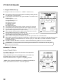
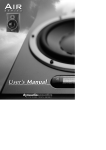
A C T I V E
S T U D I O
M O N I T O R S
OWNERS
MANUAL
4
5
7
8
9
10
10
10
Important Safety Instructions
Quick Set-Up Guide
Introduction
Concept & Design Philosophy
Unpacking & Visual Checks
Preliminary Recommendation
Monitor Placement
Orientation
11
13
14
15
16
25
27
28
29
30
30
31
Master & Slave Concept
Rear Panel Description
Operational Overview
iDP™ Display & Setup Procedure
Set-Ups
Set-Up When The Monitors are connected
Parameter Description
Bass Management
Set-Up Menu
® Parameters Available for Precision 6 iDP™ Precision 8 iDP™
® Parameters Available for TS112 iDP™ Subwoofer
Parameter Categories
32
iDP™ Remote
34
iDP SOFT™
43
44
45
Technical Specifications. Precision 6 iDP™
Technical Specifications. Precision 8 iDP™
Technical Specifications. TS212 iDP™ & TS112 iDP™ Subwoofer & iDP™ Remote
46
Performance Data
47
Dimensions
Appendix
50
iDP™ Display Messages
51
51
52
53
54
55
System Delays
X-Curves Explained
Preset List
iDP™ Cables
Declaration of Conformity
Warranty
3
IMPORTANT SAFETY INSTRUCTIONS
A C T I V E
S T U D I O
M O N I T O R S
7.1 Digital 192kHz Set-up
The diagram shows how to connect a 7.1 SDDS™ 192kHz set-up.
The Centre monitor is set as the System Controller by leaving out the
TC Link button on the rear panel.
RJ45 Network connections for the system should be connected in the
following way: Centre output to LF input
Centre output to RF input
LF output Sub input
Sub output to LI input
LF output to LS input
LI output RI input
RF output to RS input
The Centre monitor receives audio for both centre & LFE channels
via the AES input connectors (input 2 for Centre & input 3 for Sub).
The LF monitor receives audio for both LF & LS channels via the AES
input connectors (input 2 for LF & input 3 for LS).
The LI monitor receives audio for both LI & RI channels via the AES
input connectors (input 2 for LI & input 3 for RI).
The RF monitor receives audio for both RF & RS channels via the AES
input connectors (input 2 for RF & input 3 for RS).
When no Bass management is selected, only the LFE signal will be sent to the subwoofer.
When Bass management is selected, low frequency content from the 5 main channels is extracted and sent to the
subwoofer where it is summed with the LFE channel. (Only LF, Center, RF, LS, and RS contribute to the bass
management signal.).
The iDP™ Remote, iDP SOFT™ or PC-iP™ can be connected to any spare TC Link “out” connection.
! REMEMBER – To set a master monitor as the system controller the TC Link button on the rear panel
MUST be in the out position.
Alternative 7.1 Set-up.
Analog, Digital& 192kHz
If you wish to set up your system with side channels as opposed to
five “screen” channels:
Simply substitute LI(Left Inner) & RI(Right Inner), for SL (Side Left)
& SR(Side Right) as shown in the adjacent diagram.
Follow the same format for 7.1 Digital & 7.1 Digital @ 192 kHz.
* SDDS™ (Sony Dynamic Digital Sound™) is designed exclusively for
motion picture theatres; there is no consumer equivalent.
22
Connecting Two Subs
Two Subs can be connected to any of the above Set-Ups
When no Bass management is selected, no signal will be sent to
the subwoofers.
When Bass management is selected, low frequency content from the
left channel is extracted and sent to the left subwoofer.
Low frequency content from the right channel is extracted and sent to
the right subwoofer.
The iDP™ Remote, iDP SOFT™ or PC-iP™ can be connected to
any spare TC Link “out” connection.
! REMEMBER – To set a master monitor as the system controller the
TC Link button on the rear panel MUST be in the out position.
Connecting Three Subs
Three subs can be connected to any of the above Set-Ups
When no Bass management is selected, no signal will be sent
to the subwoofers.
When Bass management is selected, low frequency content from the
left channel is extracted and sent to the left subwoofer.
Low frequency content from the right channel is extracted and sent to
the right subwoofer. Low frequency content from the centre channel is
extracted and sent to the centre subwoofer.
The iDP™ Remote, iDP SOFT™ or PC-iP™ can be connected to any
spare TC Link “out” connection.
! REMEMBER – To set a master monitor as the system controller the
TC Link button on the rear panel MUST be in the out position.
23
A C T I V E
S T U D I O
M O N I T O R S
5.1 Dig/6 - Master
The diagram shows how to connect a 5.1 digital set-up using a single
master unit. The set-up requires one master monitor with the Digital
AES\EBU input card installed, four slave monitors and one subwoofer.
The Centre monitor is set as the System Controller by leaving out
the TC Link button on the rear panel.
The Centre monitor receives all six channels on the three AES\EBU
connections:Audio for the Centre and LFE channels are connected to the monitors
Digital IN connector.
Audio for the Left and Right channels are connected to the monitors
Digital IN No.2 connection on the I/0 card.
Audio for the LS and RS channels are connected to the monitors Digital
IN No.3 connection on the I/0 card.
RJ45 Network connections from the Centre monitor to the Left,
LS & subwoofer are required. Network connections from the Left to
Right, and LS to RS are required.
Clock MUST be sent on the AES/EBU connection feeding the
Centre/LFE channels (or on BNC)
When no Bass management is selected, only the LFE signal will be sent to the subwoofer.
When Bass management is selected, low frequency content from the
5 main channels is extracted and sent to the subwoofer where it is summed with the LFE channel
The iDP™ Remote, iDP SOFT™ or PC-iP™ can be connected to any spare
TC Link “out” connection.
! REMEMBER – To set a master monitor as the system controller the
TC Link button on the rear panel MUST be in the out position.
Stereo Set-up With Chains on L&R. Analog or Digital
This diagram shows how to connect a stereo setup with chains on Left and
Right. The chained monitors are fed with the same signal as the front L&R
monitors. This is the type of setup you would use if you are alternating
between a set of main (Precision 8 iDP) and nearfield (Precision 6 iDP)
monitors. With this type of set-up only one master is required.
The Left monitor is set as the System Controller by leaving out the
TC Link button on the rear panel.
The Left master monitor receives both the left and right input signals
via the analog or AES\EBU input connector(s).
The Right monitor receives audio and control via the output RJ45
TC Link connections on the Left (system controller) monitor.
The Left monitor receives audio and control via the output RJ45 TC
Link connector on the Left (system controller) monitor.
The Right monitor receives audio and control via the output RJ45 TC
Link connector on the Right monitor.
The iDP™ Remote, iDP SOFT™ or PC-iP™ can be connected to any
spare TC Link “out” connection.
! REMEMBER – To set a master monitor as the system controller the
TC Link button on the rear panel MUST be in the out position.
The “Chained” option is also achievable in all surround formats
24
SETUP when the monitors are connected
The following is a simple operational setup guide, which is carried out after the monitors are connected. The assumption
is made that you will be navigating the menus via the LCD display on the master monitor. If you have purchased the
optional software packages then refer to the iDP SOFT™ section of this manual. If you are using the PC-iP™ advanced
installers package then refer to the user manual included with this package.
1.
Connect the monitors
The monitors must be connected exactly as shown in the previous illustrated setup diagrams.
Turn on the power on each monitor.
2.
Set one monitor as the System Controller
Only one master monitor in the network can be set as the System Controller. Refer to the setup diagrams
to determine which monitor this should be. To set the master monitor as the system controller make sure
the TC LINK button on the rear panel is in the out position. All other master monitors in the setup must
be set to operate as “slaves”, this is done by pressing the TC Link button to the “in” position. If you are
changing the operational mode of the monitor you will be asked to confirm: “Mode changed set as slave?” or “Mode changed set as sys. Controller?”
Confirm by pressing the “Enter” key on the Master Display
3.
The gain setting is the first item in the main menu. The default setting in the main menu after switching
on menu is –50dB. You may have to increase this value slightly in order to hear the pink noise when
setting the monitor tasks (see 8.)
4.
Setting Bass Management
The next item in the main menu is Bass Management. Select the required Mode:Off
X-over 50Hz
X-over 80Hz
X-over Ext 50Hz
X-over Ext 80Hz
X-over THX 80Hz
X-over SC 120Hz
In stereo setups with subwoofers, the subs will only operate when the Bass Management is activated
5.
Setup Menu
Go to Setup Menu and press Enter
25
A C T I V E
6.
S T U D I O
M O N I T O R S
Reset Procedure
Three different levels of “Reset” exist. For the three Reset levels all connected monitors will be affected.
Select between the following reset options: The Reset functions are accessed by holding the ENTER key on the System Controller while
powering up:
Clear Monitor Settings
All global and local parameters in connected monitors are reset. Preset and network settings are not
affected.
Reset All Settings
This is a factory reset procedure that deletes all global and local parameter settings as well as preset
and network settings.
The following reset procedure is found in the Setup menu:
Clear Setup for entire network
Select this reset procedure to clear all network settings.
7.
Select Setup
You must define which type of setup you have: Empty
Custom
Stereo Analog
Stereo Digital
Stereo 192kHz
Surround Analog
Surround Digital
Surround 192kHz
5.1 dig/6 Master
8.
Select Monitor Tasks
Select first Monitor and press Enter.
Pink noise will be generated in one of the monitors in the setup.
Set Monitor Tasks
Choose the matching task for the position from where the pink noise is generated, for example, “Master L Front”
Press Exit when complete.
9.
External Source
BNC Input On - The monitor attempts to lock on the word Clock BNC connection.
BNC Input Off - The monitor will attempt to lock on the AES Input.
26
Parameter Description
Basic operation in all menus (when navigating the menus via the LCD display)
Use ARROW keys to select value or submenu
Use ENTER to enter menus or for confirmation, and to activate
Use EXIT to step to a higher level or to decline an operation
Values are marked with an “ * “ when they can be altered via the ARROW keys
Main Display
The Main Display indicates the position of the monitor (when set up) and the set volume for the monitor.
A “+” symbol indicates that this specific Master Unit has been set up to act as System Controller.
Bass Management †
Bass management is possible in:
- Standard Stereo with 1 Sub
- Standard Stereo with 2 Subs
- All surround modes
The Precision monitors utilize 2nd order Hi Pass filters to attenuate frequencies below the set crossover frequency.
The subwoofer utilises 4th order Low Pass filter to attenuate frequencies above the set crossover frequency.
Press ENTER to access the Select Mode
Off - Bass Management is not activated. Only the LFE channel is distributed to the Sub.
Available Crossover Frequencies:
Menu Name
X-Over 50 Hz
X-Over 80 Hz
Extension 50 Hz
Extension 80 Hz
THX Sim 80 Hz
Small Cons 120 Hz ††
Precision Filter
50Hz
80Hz
Off
Off
80Hz
120Hz
Sub 4th Order
50Hz
80Hz
50Hz
80Hz
80Hz
120Hz
Sub 2nd Order
50Hz
80Hz
50Hz
80Hz
Off
80Hz
LFE = Sub
No
No
No
No
Yes
Yes
† PC-iP
Via the iDP PC-iP™ installer package (optional software for the advanced installer) an advanced Bass Management mode
is available. In this mode a greater number of frequencies can be chosen, and all filters (Precision HPF, Sub 4th order
and Sub 2nd order) can be controlled to suit demanding & critical setups.
†† Small Cons - Small Consumer (filter to mimic a small consumer speaker)
27
A C T I V E
S T U D I O
M O N I T O R S
Bass Management
Bass management (sometimes called bass redirection) is a very important and useful tool. With conventional studio
monitors external electronics is required to achieve bass management. It is in general an absolute necessity if you want
to make a multi-channel set-up in a small room.The bass management system is designed to subtract the bass contents
of all main channels and reproduce this by the use of a subwoofer. iDP™ systems provide a number of possible crossover
frequencies that can be determined by the user.
In a basic 2-channel or 5-channel set-up (e.g. ITU-775) a sub-woofer is not specified and is not required. But producing
audio tracks to be played back on consumer equipment, one has to ensure that the mix will sound right in this situation.
Many consumer set-ups contain a subwoofer, hence it is very important to check what the summing of the bass is like.
If the program material basically is out of phase, the bass will be cancelled when summed electrically. But this is not the
case if the bass signals are reproduced by the main monitors and summed acoustically.
Important iDP™ parameters to consider when using Bass Management:-
LFE Low Pass Filter
Switches on/off a very steep (7th order) low pass filter at 120 Hz. When switched on, the LFE signal filters out content
above 120 Hz. This filter should be switched on when a media encoder is not in use and switch it off when your signal
is being played back through a decoder (Most media encoders - DTS, Dolby etc. - employ an anti-aliasing low-pass filter.
Therefore in a production environment it is important use this filter when monitoring the LFE channel in order to access
how the signal will sound after encoding / decoding (in a domestic or cinema environment).
LFE Gain
Range: 0 to +14dB
The LFE channel can be boosted by up to 18dB using this parameter.
Polarity
Range: 0 or 180º
If the Subwoofer is correctly placed, setting the Polarity parameter at 180º should result in a full Phase cancellation at
the set cross over frequency. If this is not the case – the Phase parameter described below should be adjusted.
Phase
Range: 0 to 180º
Phase Introduction
The integration of the TS112 iDP™ or TS212 iDP™subwoofer with the Precision iDP™ monitors requires on-site tuning
for best results. Apart from level calibration and choosing a Bass Management Crossover
(X-over) frequency, the issue of phase alignment remains.
For this purpose, the subwoofer has a 0-180 degree phase adjustment (in 5 degree steps) and a Phase Reverse function.
The optimal setting of these parameters will depend on several factors:
1. Room acoustics
2. Placement of monitors and listening position
3. Choice of crossover frequency
4. Whether the Precision 6 iDP™ or Precision 8 iDP™ Monitor is being used.
Phase settings are automatically saved and linked to the currently selected Crossover frequency.
Phase settings are Global settings and are therefore are not saved with individual presets.
28
Setup Menu
Press ENTER to access sub-menus
Setup
Press ENTER to access select mode. Select mode is indicated by “ * ”
Press ENTER to confirm choice
Empty
Custom
Stereo Analog
Stereo Digital
Stereo 192kHz
Surround Analog
Surround Digital
Surround 192kHz
5.1 dig/6 Master
Set Monitor Task
For the System Controller/Master monitor to identify and operate all monitors in the setup, each monitor must be given
one of the following tasks indicating function and position.
No Task
L Front
R Front
Center
(C) SUB
L Sur
R Sur
C Sur
L SUB
R SUB
LS Chain
RS Chain
L Inner
R Inner
Custom 1-4 (Reserved for future use)
Press ENTER to access task options
Use ARROW keys to select task
Press ENTER to confirm selected task
External Clock
Press ENTER to access sub-menus
BNC Sync On:
The monitor attempts to lock on the word Clock BNC.
BNC Sync Off:
The monitor will attempt to lock on the AES Input.
Calibrate Monitor
Press ENTER
Select monitor to calibrate using the ARROW keys
Press ENTER
29
A C T I V E
S T U D I O
M O N I T O R S
Parameters available for Precision 6 iDP™ and Precision 8 iDP™:Pink Noise
Calibrate
Rel.Lev.
-
Room Position
-
Bass
Treble
-
On/Off
Level calibration of the selected monitor. Range –6dB to +6dB
Relative preset volume for the selected monitor relative to the calibrated and global volume.
Range –40dB to 0dB
Neutral
Wall
Corner
Console
C. Wall - Console Wall
C. Corn - Console Corner
Bass adjustment for the selected monitor. Range –6dB to +6dB
Treble adjustment for the selected monitor. Range –6dB to +6dB
Parameters available for the subwoofer: Pink Noise
Calibrate
Rel.Lev.
-
LFE – Low Pass LFE Gain
Polarity
-
Phase
-
On/Off
Level calibration of the selected monitor. Range –18dB to +6dB
Relative preset volume for the selected monitor relative to the calibrated and global volume.
Range –40dB to 0dB
Low pass filter on the LFE channel attenuating frequencies above 120Hz
With this parameter you can boost the acoustic gain of the LFE channel
Range –6dB to +8dB
If the Subwoofer is correctly placed, setting the Phase Reverse parameter at 180º should result
in a full Phase cancellation at the set Crossover frequency. If this is not the case - the Delay
parameter should be adjusted.
Range: 0 or 180º
To time-compensate if the Sub is not placed according to the ITU 775 recommendations.
There are individual Phase settings for each of the Bass Management Crossover frequencies.
Once set, these are stored as Global settings. Range: 0 to180º
LFE channel - important
Please note that in general the LFE channel should be mixed with +10dB headroom.
If you are not able to boost your LFE monitor output from your console, +10dB gain can be
added on your Precision TS112 iDP™ or TS212 iDP™Subwoofer input. Most encoder/
decoder formats take the LFE boost into account, meaning that you should leave the
Precision TS112 iDP™ Subwoofer LFE gain at 0dB when playing back DTS or DOLBY
encoded material on your Precision IDP system. LFE gain is set at 0dB in all factory
presets, if you need to add gain on your Precision TS112 iDP™ Subwoofer please adjust
this parameter and store the new setting in a user preset location.
30
Parameter Categories
Global Parameters
These parameters apply to the entire system: Global parameters stored with presets
•
Bass Management
•
Mute Status
Global parameters NOT stored with presets
•
Ref. Levels
•
Analog Input Sensitivity
•
Selected Setup
•
BNC Sync
Local Parameters
These parameters apply to individual Precision monitors: Local parameters stored with presets
•
X-Curve
•
Parametric EQ setting (set via optional PC-iP™)
•
LFE Gain (subs)
•
LFE Low Pass (subs)
•
Rel. Level
Local parameters NOT stored with presets
•
Bass and Treble
•
Delay
•
Lock status (set via optional PC-iP™)
•
Room position
•
Calibration Level
•
Tasks
•
Phase (Subs)
•
Polarity (Subs)
Recall
•
Press ENTER and use ARROW keys to select presets
•
Press ENTER to recall/load the selected preset
If no user-preset are stored on locations 1 to 4, presets 16 to 19 are loaded instead.
Complete preset list is available on page 52.
Store
•
Press ENTER and select storage location using the ARROW keys
•
Press ENTER again to store.
Storage location can be 1-15.
Parameter can be locked via the optional PC-iP™ Installers software. When trying to change values on a locked parameter
the LCD display reads “Locked”.
31
A C T I V E
S T U D I O
M O N I T O R S
iDP™ Remote
The iDP™ remote is available and can perform the following functions: Instant access of three different user defined Reference Level settings.
Instant Preset Recall function of up to 4 presets. This way you can easily switch between different setups from your
listening position.
Mute/un-mute and solo function for each monitor in the setup.
Simple Master level adjustment using the large potentiometer
Ref. Level Selection
Preset Selection. The Shift Key switches selection
between preset 1&3 to 2&4.
Master Volume
Mute/ Un-Mute/ Solo for each Channel
32
iDP™ Remote (cont.)
Description of Functions:REF LEVEL keys 1-3
To recall Reference Levels 1-3:
Press relevant key shortly. The key LED indicates activated Reference Level.
To set Reference Level 1-3:
Set level using the large VOLUME potentiometer on the remote. Press and hold relevant Reference level key for approx.
2 seconds. The LED will flash 3 times. The new reference level is now set.
Power up state: Off (volume defined by potentiometer)
PRESET 1/3 AND 2/4 keys
These keys will recall presets 1/3 & 2/4 depending on the position of the SHIFT key.
Power up state: Off (no presets recalled).
SHIFT key
The Shift Key switches selection between preset 1&3 to 2&4.
Preset Bank 1 is presets 1and 2. Preset bank 2 is presets 3 and 4.
Power up state: Preset Bank 1 selected.
MUTE/UNMUTE - SOLO keys for the channels:
L - C - R - LS- SUB - RS
The LEDs on each key indicates the following states: LED ON Speaker on
LED OFF Speaker Mute
LED Flashing Speaker Solo
Mute/Unmute - With a single press on these keys the monitors are muted/un-muted.
Solo Function - Press and hold one of the keys to activate Solo function for the corresponding channel.
If a key is pressed (not held) the original mute status will be recalled.
Power up state: On
VOLUME potentiometer
If no REFERENCE LEVEL keys are activated this control sets the Master volume on all channels in the system.
If a REFERENCE LEVEL keys is activated, this will define the reference level.
When the REFERENCE LEVEL keys are deactivated the Master volume returns to the level defined by the position of
the VOLUME potentiometer.
Power up state: Potentiometer setting defines the volume level.
Potentiometer LED function:
When the volume level is defined by the potentiometer, the LED is on. LED goes off when volume is set by devices other
than the remote
Power up state: LED on (Potentiometer setting defines volume level).
33
A C T I V E
S T U D I O
M O N I T O R S
iDP SOFT™
iDP SOFT™ is a software editor for the Precision iDP™ monitors. All parameters that can be controlled using the display
on the System Controller can be controlled using the iDP SOFT™ program.
Installation on PC:
Place the Installation CD in your CD ROM drive and open CD contents.
Press Setup
Follow the instructions.
Installation on Mac:
Enter the Installation CD in your CD ROM drive and open CD contents.
Run the installer.
Follow the instructions.
Minimum requirements
PC Pentium 2 running Windows 95/98, 2000 or a Mac running OS X
64MB RAM
800x600 24bit screen resolution
1 free Serial port or USB. Connect from Serial or USB port to any free TC LINK connection on your Precision
iDP™ monitors using ONLY the cables described on page cables page (Appendix).
A Serial to Cat-5 cable is supplied, if a USB port is used, an optional "USB to Serial Port" converter will
be required. The "KeySpan USA 19" has been tested by Tannoy and found appropriate.
For further information please visit www.keyspan.com or contact Tannoy customer support.
Press to
enter
preset
list
34
iDP SOFT™ (cont.)
This is the Main screen from where all other iDP SOFT™ screens are accessed.
When The (((•))) network icon (upper left corner)
Is steady - The computer running the iDP SOFT™ is not correctly connected to Precision iDP™ monitors. Check connections,
cables and refer to the setup-illustrations on pages 16-24 in this manual.
Is blinking - The computer is correctly connected to your Precision iDP™ system.
The ((( ))) icon is also used to access the Network screen.
Press ((( ))) to access.
VOLUME Control
Use the mouse on the VOLUME control on the middle of the display to adjust the volume
REF LEV. keys
The three keys below the volume control allow access to the 3 user-defined Reference level settings.
To change these Ref. Levels:
Set the volume control to the desired position.
Hold cursor above Ref. Level key and select “Store” from the pop-up icons appearing.
Monitor and Sub icons
Appropriate icons as illustrated above will indicate Precision iDP™ monitors and subs. Press to access specific parameters
for the monitors.
This symbol in the Main screen indicates that the selected setup expects a monitor at a certain position
but no monitor is found. Check your connections and retry.
Bass Mgt - Bass Management
Indicates the selected Cross-over frequency for Bass Management.
Tools
When placing the cursor on top of a monitor, a few tools will appear:
Press this symbol to enter calibration pages
Press to mute the monitor
Press to solo the monitor
35
A C T I V E
S T U D I O
M O N I T O R S
iDP SOFT™ (cont.)
Preset List
Clicking on the left side of the display frame accesses the Preset List.
Presets include
Preset Volume
Mute status
Bass Management
X-curve setting
LFE Low Pass
LFE Gain
Parametric EQ (can only be adjusted using the optional PC Installers Package-PC-iP™)
All other settings can be considered “global” and are not stored with presets.
Recall presets
Select preset using your mouse and press Recall.
Store presets
Select User preset locations 1 to 15 and press Store.
Edit Name
Any User preset can be renamed.
Set the cursor in the name field and edit the name.
Locked symbol in Preset List
The “locked symbol” indicates that the preset has been locked in the PC-iP™ Installers
Software. A locked preset cannot be unlocked using iDP SOFT™, - this is only possible
with PC-iP™.
OK - Press OK to exit window.
36
iDP SOFT™ (cont.)
Network
Accessing the Network Screen
Press the ((( ))) icon in the Main screen to access the Network facilities. In this screen various global network settings
are handled.
Press <AutoDetect> to scan your COM ports. If an Precision iDP™ System is connected to any port it will be recognized.
Note that the AutoDetect function will not executed until <OK> is pressed.
<Port>
Manual select of Serial/COM port.
<Status>
Indicates the status when entering the Network screen.
<Clear Network> - Clear Setup for entire network
Select this reset procedure to clear all tasks and setup settings.
<Clear Settings> - Clear Monitor Settings
All global and local parameters in connected monitors are reset. Preset and network settings are not affected.
<Reset to Factory Settings> - Reset All Settings
A “factory” reset procedure that deletes all global and local parameter settings as well as preset and network settings.
<Upload Software to Monitors>
Software updates for the Precision iDP™ Monitors comes as (.syx) files
There are various files for monitors and subs.
Save the .syx - file to a location on your hard drive prior to the uploading the file.
Disconnect all network cables from the speaker you wish to update and connect your computer to this
individual speaker.
Press Upload Software to Monitors
Follow the onscreen instructions
Continue the process of updating one speaker at a time.
Replace the network cables.
Re-assign the appropriate monitor tasks to each speaker in your iDP system.
37
A C T I V E
S T U D I O
M O N I T O R S
iDP SOFT™ (cont.)
During Software upload various messages could be displayed:
Example:
“Precision monitor updated successfully” means the Precision monitor has been updated successfully.
Precision iDP™ monitor updated successfully
If the message: “Failed to update Precision iDP™ monitors” – means the monitor has reported an error during software
upload. This could be caused by communication errors. Please retry.
<OK>
Press to exit screen and execute AutoDetect command if marked.
System Setup
<Configuration>
Select your current setup.
<Analog Gain>
Range: +9dBu, +15dBu, +21dBu or +27dBu
Set to match analog Input gain to match the signal fed to
the optional Analog Input card.
<BNC Sync>
BNC Sync On:
The monitor attempts to lock on the word clock BNC.
38
Monitor Assignment
Task
Press monitor symbol to activate pink noise test-tone.
Then select task for the monitor now playing the noise. Serial number and type will be indicated.
A monitor marked with a question mark indicates that an “unknown” monitor has
been detected. (This icon is darker in colour than the previously mentioned ‘monitor
not found’)
Scan System
Press the magnifying-glass to scan the entire system for connected units.
Save Settings
Load Settings
- All settings except “preset settings” are saved to a back-up file.
- Press and browse to select file to load. Follow the instructions.
Calibrate - Main Monitors
Pink Noise
Solo
Mute
Parameters and settings for the Main monitors are controlled in this screen
The screen is accessed via the Main Screen by holding the cursor above the desired monitor and selecting
the hammer icon.
Room position
Range: Neutral, Wall, Corner, Console, C. Wall or C. Corn
Select according to the actual position of the monitor.
X Curve
Range: Off, X-Curve 1 or X-Curve-2
Two modifications of X-222 curve are available.
See page 51.
39
A C T I V E
S T U D I O
M O N I T O R S
iDP SOFT™ (cont.)
Calibrated Level
Level calibration of the selected monitor.
Relative Level
Preset volume for the selected monitor relative to the calibrated and global volume.
Use Parametric EQ
This will be marked if the Parametric EQ is activated via the PC-iP™ program. Bass and Treble settings will be disabled.
Bass/Treble
Range: -6dB to +6dB. Bass and Treble adjustment for the selected monitor.
The Bass/Treble functions are not available when the Parametric EQ is activated using the PC-iP™ program.
Mute
Press to mute the selected monitor.
Solo
Press to solo the selected monitor.
Pink Noise
Press to generate Pink Noise in
the selected monitor.
Calibrate – Subwoofer
Parameters and settings for the Subwoofers is controlled via this screen.
The screen is accessed from the Main Screen by holding the cursor above the desired Sub and selecting the
hammer icon.
40
iDP SOFT™ (cont.)
Phase
Range: 0-180°
To time-compensate if the Sub cannot be placed according to the ITU 775 recommendations. There are individual Phase
settings for each of the Bass Management Cross-over frequencies. Once set, these are stored as Global settings.
Polarity
Range: 0 or 180 deg.
Mark to activate.
Calibrated Level
Level calibration of the selected monitor.
Relative Level
Preset volume for the selected monitor relative to the
calibrated and global volume.
LFE Gain
Range: 0 to 14dB
With this parameter you can boost the gain of the LFE
channel.
LFE Low Pass Filter
Mark to activate.
Mute
Press to mute the selected monitor.
Solo
Press to solo the selected monitor.
Pink Noise
Press to generate Pink Noise
in the selected monitor.
41
A C T I V E
S T U D I O
M O N I T O R S
Chained monitors
If several monitors are chained on the same task (e.g. LSur-LSChain) a dropdown menu will appear as shown below. To calibrate a
chained monitor simply select from the list.
42
Technical Specifications - Precision 6 iDP
System (Master & Slaves)
System
Frequency Response (1)
Max. SPL (@ 1m) (2)
Dispersion (-6dB)
Crossover Frequency
Drive units
Cabinet LF Alignment
Dimensions (H x W x D)
Cabinet Construction
Total weight
Electronic System
Mains
Power Consumption
Amplifier
3-Way semi-active near field monitor
56Hz – 51kHz (+/- 2dB)
117dB (continuous)
90 degrees
1.9kHz (DSP generated) & 16kHz (passive)
165mm (6") Tannoy Dual Concentric™ constant directivity driver with
multiple fibre paper pulp cone.
25mm (1") titanium dome Wideband™ SuperTweeter™
Neodymium magnet system
Optimised bass reflex loaded
356mm x 220mm x 369mm (14” x 85/8” x 141/2”)
MDF cabinet and front baffle, tongue and groove front and back
Black cabinet Grey painted baffle with brushed aluminium inlay
Black anodized aluminum back plate
12 kg (26.4lbs)
Voltage 100 to 240Vac, 50 – 60Hz (auto – select)
45W @ 1/8 full power (IEC 6065)
Bass/midrange – 200 Watts Class D
Tweeter & SuperTweeter™ – 200 Watts Class D
System Sample Rates:
Internal
External
96 kHz (except when slaved to digital input or word clock input)
96, 88.2, 64, 48, 44.1 or 32 kHz (optional 192kHz)
Digital Section (Master only):
I/O connectors
Formats
Word Clock
Display
Operation
XLR (2 channels AES/EBU in). 3 x RJ45 proprietary TC LINK
AES\EBU
Input BNC, 75 , 0.6 to 10 Vpp
2 x 16 character dot matrix
Menu system / four buttons
Analogue Section (Master only):
Input connectors
Impedance
Selectable Full Scale Input level
Dynamic Range
THD+N
Cross-talk
XLR balanced (pin 2+, pin 3-)
10/3 k (balanced/unbalanced)
+9, +15, +21, +27 dBu
> 113 dB typ. (unweighted), BW: 20-20kHz
< -105 dB typ. @ 1 kHz, -3 dBFS
< -120 dB, 20 Hz to 20 kHz
A to D Conversion
24 bit (Dual bit delta sigma sampling at 4.1/5.6/6.1/6.1MHz)
Slaves Only:
I/O connector’s
2 x RJ45 proprietary TC LINK
The typical listening distance for Precision 6 iDP is 1-2m
The typical room size for Precision 6 iDP is 40-90 m3
NOTES
(1)
+/- 3 dB, measured at 1m in an anechoic chamber. (2) Peak SPL at mix position for 1 pair driven.
Tannoy operates a policy of continuous research and development. The introduction of new materials or manufacturing methods will always equal or exceed the published
specifications which Tannoy reserve the right to alter without prior notice. Please verify the latest specifications when dealing with critical applications.
43
A C T I V E
S T U D I O
M O N I T O R S
Technical Specifications- Precision 8 iDP
System (Master & Slaves)
System
Frequency Response (1)
Max. SPL (@ 1m) (2)
Dispersion (-6dB)
Crossover Frequency
Drive units
Cabinet LF Alignment
Dimensions (H x W x D)
Cabinet Construction
Total weight
Electronic System
Mains Voltage
Power Consumption
Amplifier
3-Way semi-active near field monitor
43Hz – 51kHz (+/- 2dB)
120dB (continuous)
90 degrees
1.7kHz (DSP generated) & 16kHz (passive)
200mm (8") Tannoy Dual Concentric™ constant directivity driver with
multiple fibre paper pulp cone.
25mm (1") titanium dome Wideband™ SuperTweeter™,
Neodymium magnet system
Optimised bass reflex loaded
440mm x 272mm x 369mm (173/8” x 103/4” x 141/2”)
MDF cabinet and front baffle, tongue and groove front and back
Black cabinet grey painted baffle with brushed aluminium inlay
Black anodized aluminum back plate
17 kg (37.4lbs)
100 to 240Vac, 50 – 60Hz (auto – select)
45W @ 1/8 full power (IEC 6065)
Bass/midrange – 200 Watts Class D
Tweeter & SuperTweeter™ 200 Watts Class D
System Sample Rates:
Internal
External
96 kHz (except when slaved to digital input or word clock input)
96, 88.2, 64, 48, 44.1 or 32 kHz (optional 192kHz)
Digital Section (Master only):
I/O connectors
Formats
Word clock
Display
Operation
XLR (2 channels AES/EBU in). 3 x RJ45 proprietary TC LINK
AES\EBU
Input BNC, 75 , 0.6 to 10 Vpp
2 x 16 character dot matrix
Menu system / four buttons
Analogue Section (Master only):
Input connectors
Impedance
Selectable Full Scale Input Level
Dynamic Range
THD+N
Cross-talk
XLR balanced (pin 2+, pin 3-)
10/3 k (balanced/unbalanced)
+9, +15, +21, +27 dBu
> 113 dB typ. (unweighted), BW: 20-20kHz
< -105 dB typ. @ 1 kHz, -3 dBFS
< -120 dB, 20 Hz to 20 kHz
A to D Conversion
24 bit (Dual bit delta sigma sampling at 4.1/5.6/6.1/6.1MHz)
Slaves Only:
I/O connector’s
2-x RJ45 proprietary TC LINK
The typical listening distance for Precision 8 iDP is 1.3 -2.8 m
The typical room size for Precision 8 iDP is 50-100 m3
NOTES
(1)
+/- 3 dB, measured at 1m in an anechoic chamber. (2) Peak SPL at mix position for 1 pair driven.
Tannoy operates a policy of continuous research and development. The introduction of new materials or manufacturing methods will always equal or exceed the published
specifications which Tannoy reserve the right to alter without prior notice. Please verify the latest specifications when dealing with critical applications.
44
Technical Specifications - TS212 iDP™ & TS112 iDP™ Subwoofer & iDP™ Remote
Technical Specifications
TS212 iDP™ Subwoofer
TS112 iDP™ Subwoofer & iDP™
System
Frequency Response
Max. SPL (@ 1m)
Crossover Frequency
Drive units
Cabinet Volume/LF Alignment
Dimensions (H x W x D)
Active Subwoofer
25Hz – 150Hz (+/- 3dB)
124dB (continuous)
Set in bass management (DSP Generated)
2 x 300mm (12") Aluminium Cone
45 Litres/Infinite baffle
520mm x 471mm x 497mm
(201/2” x 185/8” x 195/8”)
Active Subwoofer
25Hz – 150Hz (+/- 3dB)
118dB (continuous)
Set in bass management (DSP Generated)
1 x 300mm (12") Aluminium Cone
22 Litres/Infinite baffle
384mm x 366mm x 398mm
(151/8” x 143/8” x 155/8”)
Cabinet Construction
MDF
Gray suede paint finish on top with silver insert
Black Fabric on sides
Black anodised aluminium back plate
MDF
Gray suede paint finish.
Total weight
51kg (112.2lbs)
25kg (55lbs)
Electronic System
Mains Voltage
Power Consumption
Amplifier
115 or 230Vac, 50 – 60Hz (switchable)
45W @ 1/8 Full Power (IEC 60065)
1500 W PWM amp
115 or 230Vac, 50 – 60Hz (switchable)
45W @ 1/8 Full Power (IEC 60065)
750 W PWM amp
96 kHz (except when slaved to digital input
or word clock input)
96, 88.2, 64, 48, 44.1 or 32 kHz
(optional 192kHz)
96 kHz (except when slaved to digital input
or word clock Input)
96, 88.2, 64, 48, 44.1 or 32 kHz
(optional 192kHz)
2 x RJ45 proprietary TC LINK
> 113 dB typ. (unweighted)
< -105 dB typ. @ 1 kHz, -3 dBFS
< -120 dB
24 bit (Dual bit delta sigma sampling at
4.1/5.6/6.1/6.1 MHz)
2 x RJ45 proprietary TC LINK
> 113 dB typ. (unweighted)
< -105 dB typ. @ 1 kHz, -3 dBFS
< -120 dB
24 bit (Dual bit delta sigma sampling at
4.1/5.6/6.1/6.1 MHz)
System Sample Rates:
Internal
External
Digital Section (Slave only):
I/O connectors
Dynamic Range
THD+N
Cross-talk
A to D Conversion
Black anodised aluminium back plate.
45
A C T I V E
S T U D I O
M O N I T O R S
Dimensions : Precision 6 iDP™
Precision 6 iDP™
369.0mm (141/2”)
337.0mm (131/4”)
220.0mm (85/8”)
356mm (14”)
46
Dimensions : Precision 8 iDP™
Precision 8 iDP™
369.0mm (141/2”)
272mm (103/4”)
337.0mm (131/4”)
440mm
(175/16”)
47
A C T I V E
S T U D I O
M O N I T O R S
498mm
(19 5/8”)
471mm (18 9/16”)
520mm (201/2”)
Dimensions : Precision TS212 iDP™ (Grey/Silver)
384mm
(15 1/8”)
48
366mm (14 3/8”)
398mm (155/8”)
Dimensions : Precision TS112 iDP™ (Grey)
iDP™ Display Messages
The following is an explanation of Error Messages, etc may appear on a Master monitor Display:"!" as "96 kHz Center!”
The "!" indicates that the monitor is not connected to the network. The volume is then automatically set to -50 dB for the
monitor not recognized in the network.
"+" as "96 kHz L Front+":
The "+" indicates that the monitor you are looking at is the System Controller.
>> A-Input Lo <<
This message is displayed in analog setups only and indicates that the Input level has been detected to be between 60dB and -20dB for a period longer than 3 minutes. This is an indication to increase the Analog Input Gain.
Analog Input gain range:
+9dBu, +15dBu, +21dBu or 27 dBu.
>> A-Input Hi <<
This message is displayed in analog setups only and indicates that an Input level near 0dB is detected. (peaks @ 2 sec.
Above -1 dB). This is a warning and you should turn down the Analog input gain
Analog Input gain range:
+9dBu, +15dBu, +21dBu or 27 dBu.
>> PSU error <<
Displayed if the power supplies fails. The power will be turned off and the monitor will operate. Contact TANNOY Service
Department.
<Locked>
Displayed when a parameter is locked by the PC-iP™ installer software and cannot be changed.
Parameter lock can only be unlocked with the PC-iP™ software.
Standby
Displayed when no Input signal has been detected for the time specified in the Utility Menu. below -65 dB. The Amplifier
is turned off. Standby mode is released as soon a signal level above -65dB has been detected.
>> Power save <<
Displayed when no signal has been detected on all monitors on the network for the time specified in the Utility Menu.
Power is turned off. Exit this mode by pressing any key on system controller or adjusting volume from the remote.
49
A C T I V E
S T U D I O
M O N I T O R S
System Delays
Sample Rate
Digital Input
Analog Input*
AES or WC
in kHz
Converter
kHz
Samples
@ input Rate
m/seconds
cm
Samples @
Converter Rate
m/seconds
cm
32.00
64.00
93.00
2.91
100
73.00
1.14
39
44.10
88.20
68.00
1.54
53
73.00
0.83
28
48.00
96.00
40.00
0.83
29
73.00
0.76
26
64.00
64.00
34.00
0.53
18
73.00
1.14
39
88.20
88.20
34.00
0.39
13
73.00
0.83
28
96.00
96.00
34.00
0.35
12
73.00
0.76
26
* In Analog Input mode without WC Input selected, the system runs on the Master monitor's own 96kHz clock.
X – Curves Explained
For small rooms, defined as less than 5300 cubic feet or 150 cubic meters, ANSI/SMPTE 222M calls for a modification
of the X-curve with flat natural response to 2kHz and then a 1.5dB per octave roll off above 2 kHz. This curve is useful
when mixing in a small room and playing back in a large room.
Another variation on the curve is to begin the high-end roll off at 4 kHz and roll off 3dB per octave instead of 1.5 per
octave.
50
BassMgt. 80Hz
BassMgt. 95Hz
BassMgt. 110Hz
BassMgt. 115Hz
BassMgrt.120Hz
Cinema Flat
Cine X-curve
Cine X-curve2
Cinema X+50Hz
Cinema X+80Hz
CinemX+120Hz
Cinema 80Hz
Cinema 120Hz
OB Van 120Hz
Neutral
18
19
20
21
22
23
24
25
26
27
28
29
30
31
32
All parameters neutral - a good starting point
Music, video and post for domestic (Not Cinema) use Stereo, 5.1, 5.3 and 6.1
Music, video and post for domestic (Not Cinema) use Stereo, 5.1, 5.3 and 6.1
Music, video and post for domestic (Not Cinema) use Stereo, 5.1, 5.3 and 6.1
Music, video and post for domestic (Not Cinema) use Stereo, 5.1, 5.3 and 6.1
Music, video and post for domestic (Not Cinema) use Stereo, 5.1, 5.3 and 6.1
Music, video and post for domestic (Not Cinema) use Stereo, 5.1, 5.3 and 6.1
Mixing for Cinema without compensation
for X-curve. 5.1
Mixing for Cinema in a small room - compensates
for X-curve. 5.1
Mixing for Cinema in a small room - compensates
for modified X-curve. 5.1
Mixing for Cinema with small room X-curve 0
compensation and bass Management.
Mixing for Cinema with small room X-curve
compensation and bass Management.
Mixing for Cinema with small room X-curve
compensation and bass Management.
Mixing for Cinema with Bass management but
without compensation for X-curve
Mixing for Cinema with Bass management but
without compensation for X-curve
OB vans and very small rooms where rear-channels
are close to sweetspot
All parameters neutral - a good starting point
Typical applications
0
-2
-3
-3
-3
-3
-3
0
0
0
0
0
0
0
0
0
0
C
0
-2
-3
-3
-3
-3
-3
-3
-3
-3
0
0
0
0
0
0
0
R
0
0
0
0
0
0
0
-3
-3
-3
0
0
0
0
0
0
0
Ls
0
0
0
0
0
0
0
0
0
0
0
0
0
0
0
0
0
Rs
0
0
0
0
0
0
0dB Gain
0dB Gain
0dB Gain
0dB Gain
0dB Gain
0dB Gain
0dB Gain
0dB Gain
0dB Gain
0dB Gain
0dB Gain
0dB Gain
0dB Gain
0dB Gain
0dB Gain
0dB Gain
0dB Gain
SUB LFE
Off
120Hz
120Hz
80Hz
120Hz
80Hz
50Hz
Off
Off
Off
120Hz
115Hz
110Hz
95Hz
80Hz
Off
50Hz
-over
Bass M. X
Off
Off
Off
On
On
On
On
Off
On
Off
Off
Off
Off
Off
Off
Off
Off
Off
Off
Off
Off
Off
Off
Off
On
Off
Off
Off
Off
Off
Off
Off
Off
Off
51
X-Curve 1 X-Curve 2
LFE Gain - Please note that in general the LFE channel should be mixed with +10dB headroom. If you are not able to boost your LFE monitor output from your console, +10dB
gain can be added on your Subwoofer input. Most encoder/decoder formats take the LFE boost into account, meaning that you should leave the Subwoofer LFE gain at 0dB
when playing back a DTS™ or DOLBY™ encoded material on your Precision iDP™ system.
0
0
0
0
0
0
0
0
0
0
0
0
0
0
0
0
0
L
Preset Level (dB)
Presets 1 - 15 are "empty" until you choose to store a custom preset; after which it will display "User Preset #"
X-curve #1 - ANSI / SMPTE222M (1.5dB roll off per oct. from 2kHz))
X-curve #2 - ANSI / SMPTE222M Mod. (3dB roll off per oct. from 4kHz)
Neutral
BassMgt. 50Hz
16
17
Factory Presets
Empty or User Preset
1 thru 15
M O N I T O R S
Display Name
S T U D I O
Preset #
A C T I V E
A C T I V E
S T U D I O
M O N I T O R S
Cables
Below is a guide to the cables used in iDP™ set-up’s.
TC LINK Standard Cat-5 cables
Maximum Cable Length : 15 metres.
Cable type : Shielded Ethernet Cable Category 5.
Connector type : RJ45
This connection carries Digital audio (24 bit) and network control information.
P1 (pin No.)
P2(pin No.)
1
2
3
4
5
6
7
8
1
2
3
4
5
6
7
8
AES/EBU Standard cables
Maximum Cable Length: 100 m
Cable type: 110 Ohm
Connector type: XLR
Colour
Brown
White/Brown
Green
White/Blue
Blue
White/Green
Orange
White/Orange
Pin1
Pin2
Pin3
Serial to Cat-5 cable
This cable is included with the iDP SOFT™ and PC-iP™.
This is a proprietary cable with integral
Electronics. For use with iDP™ Systems only.
USB to COM 9pin
This cable isNOT included with iDP SOFT™ or PC-iP™.
Use this type of converter along with the Cat5 to Serial cable
described above if your computer has a USB connection
only and no serial port.
52
Pin1
Pin2
Pin3
Ground
Hot (+)
Cold (-)
Declaration Of Conformity
The following apparatus is/are manufactured in the United Kingdom by Tannoy Ltd of Rosehall
Industrial Estate, Coatbridge, Scotland, ML5 4TF and TC Electronic A/S, Sindalsvej 34, 8240
Risskov, Denmark.
The following equipment is marked with the CE label and conform(s) to the protection requirements
of the European Electromagnetic Compatibility Standards and Directives. The apparatus is
designed and constructed such that electromagnetic disturbances generated do not exceed
levels allowing radio and telecommunications equipment and other apparatus to operate as
intended, and, the apparatus has an adequate level of intrinsic immunity to electromagnetic
disturbance to enable operation as specified and intended.
Details of the Apparatus:
Precision 6 iDP™
Precision 8 iDP™
TS212 iDP™
TS112 iDP™
iDP™ Remote
The equipment listed above is covered by this certificate and marked with the CE-label conforms with following standards:
EN 60065
(IEC 60065)
Safety requirements for mains
operated electronic and related
apparatus for household and similar
general use
EN 55103-1
Product family standard for audio,
video, audio-visual and entertainment
lighting control apparatus for
professional use. Part 1: Emission.
EN 55103-2
Product family standard for audio,
video, audio-visual and entertainment
lighting control apparatus for
professional use. Part 2: Immunity.
With reference to regulations in following directives:
73/23/EEC, 89/336/EEC
Signed:
Position:
Engineering Director – Professional Products
Tannoy Limited
Date:
14/12/2005
For Tannoy Ltd
53
A C T I V E
S T U D I O
M O N I T O R S
Warranty
No maintenance of the Precision iDP™ Monitor is necessary.
All components are guaranteed for a period of one year from the date of manufacture, subject to the absence of, or
evidence of, misuse, overload or accidental damage.
For further information please contact your dealer or the distributor in your country.
If you cannot locate your distributor please contact:
Customer Services, Tannoy Ltd, Coatbridge, Strathclyde ML5 4TF
T: +44 (0) 1236 420199 F: +44 (0) 1236 428230
DO NOT SHIP ANY PRODUCT TO TANNOY WITHOUT PREVIOUS AUTHORISATION
This warranty in no way affects your statutory rights.
Our policy commits us to incorporating improvements to our products through continuous research
and development. Please confirm current specifications for critical applications with your supplier.
54
A C T I V E
S T U D I O
M O N I T O R S
Check periodically for the latest manual revision that will always available for download from
www.tannoy.com The issue number of this manual is located below
Issue 1
Software Version 1.53
Part No. 6481 0473
GH 01 December 2005
Tannoy United Kingdom
T: +44 (0) 1236 420199
F: +44 (0) 1236 428230
E: [email protected]
Tannoy North America
T: (519) 745 1158
F: (519) 745 2364
E: [email protected]
Tannoy Deutschland
T: 0180 1111 88 1
F: 0180 1111 88 2
E: [email protected]