1
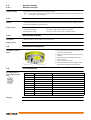
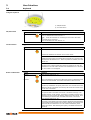
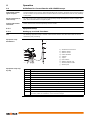
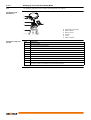
GeoMax Zenith25 Pro Series User Manual Version 1.0 Introduction This manual contains important safety directions as well as instructions for setting up the product and operating it. Refer to "1 Safety Directions" for further information. Read carefully through the User Manual before you switch on the product. Product identification The type and serial number of your product are indicated on the type plate. Always refer to this information when you contact your agency or GeoMax authorised service workshop. Trademarks • Windows is a registered trademark of Microsoft Corporation in the United States and other countries • Bluetooth® is a registered trademark of Bluetooth SIG, Inc. • microSD Logo is a trademark of SD-3C, LLC. All other trademarks are the property of their respective owners. Validity of this manual This manual applies to the Zenith25 Pro GNSS instrument with the models GSM (without TNC plug) and GSM/UHF. Introduction Zenith25 Pro | 2 Table of Contents In this manual Chapter 1 Safety Directions 1.1 1.2 1.3 1.4 1.5 1.6 1.7 2 2.4 2.5 2.6 4.2 4.3 4.4 6 Guidelines for Correct Results with GNSS Surveys 4.1.1 Equipment Setup Batteries 4.2.1 Operating Principles 4.2.2 Inserting and removing the Battery Inserting a microSD card Inserting a SIM card 14 14 14 19 19 19 20 21 Transport Storage Cleaning and Drying Technical Data 6.1 6.2 Table of Contents 9 9 9 10 10 10 10 10 10 11 12 12 13 Care and Transport 5.1 5.2 5.3 4 4 4 5 5 5 7 8 Keyboard LED Indicators Operation 4.1 5 System Components Container Contents System Concept 2.3.1 Software Concept 2.3.2 Power Concept 2.3.3 Data Storage Concept Instrument Components Pin Assignments The Mechanical Reference Plane, MRP User Interface 3.1 3.2 4 General Introduction Definition of Use Limits of Use Responsibilities Hazards of Use Electromagnetic Compatibility EMC FCC Statement, Applicable in U.S. Description of the System 2.1 2.2 2.3 3 Page Technical Data 6.1.1 Tracking Characteristics 6.1.2 Accuracy 6.1.3 GNSS antenna specifications 6.1.4 Internal devices 6.1.5 Technical Data 6.1.6 Environmental specifications Conformity to National Regulations 22 22 22 22 23 23 23 23 23 23 24 24 25 Zenith25 Pro | 3 1 Safety Directions 1.1 General Introduction Description The following directions enable the person responsible for the product, and the person who actually uses the equipment, to anticipate and avoid operational hazards. The person responsible for the product must ensure that all users understand these directions and adhere to them. About Warning Messages Warning messages are an essential part of the safety concept of the instrument. They appear wherever hazards or hazardous situations can occur. Warning messages... • make the user alert about direct and indirect hazards concerning the use of the product. • contain general rules of behaviour. For the users‘ safety, all safety instructions and safety messages shall be strictly observed and followed! Therefore, the manual must always be available to all persons performing any tasks described herein. DANGER, WARNING, CAUTION and NOTICE are standardized signal words for identifying levels of hazards and risks related to personal injury and property damage. For your safety it is important to read and fully understand the table below with the different signal words and their definitions! Supplementary safety information symbols may be placed within a warning message as well as supplementary text. Type Description DANGER Indicates an imminently hazardous situation which, if not avoided, will result in death or serious injury. WARNING Indicates a potentially hazardous situation or an unintended use which, if not avoided, could result in death or serious injury. CAUTION Indicates a potentially hazardous situation or an unintended use which, if not avoided, may result in minor or moderate injury. NOTICE 1.2 Indicates a potentially hazardous situation or an unintended use which, if not avoided, may result in appreciable material, financial and environmental damage. Important paragraphs which must be adhered to in practice as they enable the product to be used in a technically correct and efficient manner. Definition of Use Intended use • • • • • • • Computing with software. Recording measurements. Carrying out measurement tasks using various GNSS measuring techniques. Recording GNSS and point related data. Remote control of product. Data communication with external appliances. Measuring raw data and computing coordinates using carrier phase and code signal from GNSS satellites. Reasonably foreseeable misuse • • • • • • • • • • • Use of the product without instruction. Use outside of the intended use and limits. Disabling safety systems. Removal of hazard notices. Opening the product using tools, for example screwdriver, unless this is permitted for certain functions. Modification or conversion of the product. Use after misappropriation. Use of products with recognisable damages or defects. Use with accessories from other manufacturers without the prior explicit approval of GeoMax. Inadequate safeguards at the working site. Controlling of machines, moving objects or similar monitoring application without additional controland safety installations. Safety Directions Zenith25 Pro | 4 1.3 Limits of Use Environment Suitable for use in an atmosphere appropriate for permanent human habitation: not suitable for use in aggressive or explosive environments. Local safety authorities and safety experts must be contacted before working in hazardous areas, or close to electrical installations or similar situations by the person in charge of the product. DANGER 1.4 Responsibilities Manufacturer of the product GeoMax AG, CH-9443 Widnau, hereinafter referred to as GeoMax, is responsible for supplying the product, including the user manual and original accessories, in a safe condition. Person responsible for the product The person responsible for the product has the following duties: • To understand the safety instructions on the product and the instructions in the user manual. • To ensure that it is used in accordance with the instructions. • To be familiar with local regulations relating to safety and accident prevention. • To inform GeoMax immediately if the product and the application becomes unsafe. • To ensure that the national laws, regulations and conditions for the operation of e.g. radio transmitters or lasers are respected. 1.5 Hazards of Use DANGER Because of the risk of electrocution, it is dangerous to use poles and extensions in the vicinity of electrical installations such as power cables or electrical railways. Precautions: Keep at a safe distance from electrical installations. If it is essential to work in this environment, first contact the safety authorities responsible for the electrical installations and follow their instructions. WARNING During dynamic applications, for example stakeout procedures there is a danger of accidents occurring if the user does not pay attention to the environmental conditions around, for example obstacles, excavations or traffic. Precautions: The person responsible for the product must make all users fully aware of the existing dangers. WARNING Inadequate securing of the working site can lead to dangerous situations, for example in traffic, on building sites, and at industrial installations. Precautions: Always ensure that the working site is adequately secured. Adhere to the regulations governing safety and accident prevention and road traffic. CAUTION If the accessories used with the product are not properly secured and the product is subjected to mechanical shock, for example blows or falling, the product may be damaged or people can sustain injury. Precautions: When setting-up the product, make sure that the accessories are correctly adapted, fitted, secured, and locked in position. Avoid subjecting the product to mechanical stress. WARNING If the product is used with accessories, for example masts, staffs, poles, you may increase the risk of being struck by lightning. Precautions: Do not use the product in a thunderstorm. Safety Directions Zenith25 Pro | 5 If the product is used with accessories, for example on masts, staffs, poles, you may increase the risk of being struck by lightning. Danger from high voltages also exists near power lines. Lightning, voltage peaks, or the touching of power lines can cause damage, injury and death. Precautions: • Do not use the product in a thunderstorm as you can increase the risk of being struck by lightning. • Be sure to remain at a safe distance from electrical installations. Do not use the product directly under or close to power lines. If it is essential to work in such an environment contact the safety authorities responsible for electrical installations and follow their instructions. • If the product has to be permanently mounted in an exposed location, it is advisable to provide a lightning conductor system. A suggestion on how to design a lightning conductor for the product is given below. Always follow the regulations in force in your country regarding grounding antennas and masts. These installations must be carried out by an authorised specialist. • To prevent damages due to indirect lightning strikes (voltage spikes) cables, for example for antenna, power source or modem should be protected with appropriate protection elements, like a lightning arrester. These installations must be carried out by an authorised specialist. • If there is a risk of a thunderstorm, or if the equipment is to remain unused and unattended for a long period, protect your product additionally by unplugging all systems components and disconnecting all connecting cables and supply cables, for example, instrument - antenna. DANGER Lightning conductors Suggestion for design of a lightning conductor for a GNSS system: 1) On non-metallic structures Protection by air terminals is recommended. An air terminal is a pointed solid or tubular rod of conducting material with proper mounting and connection to a conductor. The position of four air terminals can be uniformly distributed around the antenna at a distance equal to the height of the air terminal. The air terminal diameter should be 12 mm for copper or 15 mm for aluminium. The height of the air terminals should be 25 cm to 50 cm. All air terminals should be connected to the down conductors. The diameter of the air terminal should be kept to a minimum to reduce GNSS signal shading. 2) On metallic structures Protection is as described for non-metallic structures, but the air terminals can be connected directly to the conducting structure without the need for down conductors. Air terminal arrangement, plan view a b c GS_039 Grounding the instrument/antenna a) Antenna b) Support structure c) Air terminal a b c d e GS_040 a) b) c) d) e) Antenna Lightning conductor array Antenna/instrument connection Metallic mast Connection to earth WARNING During the transport, shipping or disposal of batteries it is possible for inappropriate mechanical influences to constitute a fire hazard. Precautions: Before shipping the product or disposing of it, discharge the batteries by running the product until they are flat. When transporting or shipping batteries, the person in charge of the product must ensure that the applicable national and international rules and regulations are observed. Before transportation or shipping contact your local passenger or freight transport company. WARNING High mechanical stress, high ambient temperatures or immersion into fluids can cause leakage, fire or explosions of the batteries. Precautions: Protect the batteries from mechanical influences and high ambient temperatures. Do not drop or immerse batteries into fluids. Safety Directions Zenith25 Pro | 6 WARNING If battery terminals are short circuited e.g. by coming in contact with jewellery, keys, metalized paper or other metals, the battery can overheat and cause injury or fire, for example by storing or transporting in pockets. Precautions: Make sure that the battery terminals do not come into contact with metallic objects. WARNING Incorrect fastening of the external antenna to vehicles or transporters poses the risk of the equipment being broken by mechanical influence, vibration or airstream. This may result in accident and physical injury. Precautions: Attach the external antenna professionally. The external antenna must be secured additionally, for example by use of a safety cord. Ensure that the mounting device is correctly mounted and able to carry the weight of the external antenna (>1 kg) safely. WARNING If the product is improperly disposed of, the following can happen: • If polymer parts are burnt, poisonous gases are produced which may impair health. • If batteries are damaged or are heated strongly, they can explode and cause poisoning, burning, corrosion or environmental contamination. • By disposing of the product irresponsibly you may enable unauthorised persons to use it in contravention of the regulations, exposing themselves and third parties to the risk of severe injury and rendering the environment liable to contamination. Precautions: The product must not be disposed with household waste. Dispose of the product appropriately in accordance with the national regulations in force in your country. Always prevent access to the product by unauthorised personnel. Product-specific treatment and waste management information is available from GeoMax AG. WARNING 1.6 Only GeoMax authorised service workshops are entitled to repair these products. Electromagnetic Compatibility EMC Description The term Electromagnetic Compatibility is taken to mean the capability of the product to function smoothly in an environment where electromagnetic radiation and electrostatic discharges are present, and without causing electromagnetic disturbances to other equipment. Electromagnetic radiation can cause disturbances in other equipment. WARNING Although the product meets the strict regulations and standards which are in force in this respect, GeoMax cannot completely exclude the possibility that other equipment may be disturbed. CAUTION There is a risk that disturbances may be caused in other equipment if the product is used with accessories from other manufacturers, for example field computers, personal computers or other electronic equipment, non-standard cables or external batteries. Precautions: Use only the equipment and accessories recommended by GeoMax. When combined with the product, they meet the strict requirements stipulated by the guidelines and standards. When using computers or other electronic equipment, pay attention to the information about electromagnetic compatibility provided by the manufacturer. CAUTION Disturbances caused by electromagnetic radiation can result in erroneous measurements. Although the product meets the strict regulations and standards which are in force in this respect, GeoMax cannot completely exclude the possibility that the product may be disturbed by intense electromagnetic radiation, for example, near radio transmitters, two-way radios or diesel generators. Precautions: Check the plausibility of results obtained under these conditions. CAUTION If the product is operated with connecting cables attached at only one of their two ends, for example external supply cables, interface cables, the permitted level of electromagnetic radiation may be exceeded and the correct functioning of other products may be impaired. Precautions: While the product is in use, connecting cables, for example product to external battery, product to computer, must be connected at both ends. Safety Directions Zenith25 Pro | 7 Radios or digital cellular phones Use of product with radio or digital cellular phone devices: Electromagnetic fields can cause disturbances in other equipment, in installations, in medical devices, for example pacemakers or hearing aids and in aircraft. It can also affect humans and animals. Precautions: Although the product meets the strict regulations and standards which are in force in this respect, GeoMax cannot completely exclude the possibility that other equipment can be disturbed or that humans or animals can be affected. WARNING • • • 1.7 Do not operate the product with radio or digital cellular phone devices in the vicinity of filling stations or chemical installations, or in other areas where an explosion hazard exists. Do not operate the product with radio or digital cellular phone devices near to medical equipment. Do not operate the product with radio or digital cellular phone devices in aircraft. FCC Statement, Applicable in U.S. The greyed paragraph below is only applicable for products without radio. WARNING This equipment has been tested and found to comply with the limits for a Class B digital device, pursuant to part 15 of the FCC rules. These limits are designed to provide reasonable protection against harmful interference in a residential installation. This equipment generates, uses and can radiate radio frequency energy and, if not installed and used in accordance with the instructions, may cause harmful interference to radio communications. However, there is no guarantee that interference will not occur in a particular installation. If this equipment does cause harmful interference to radio or television reception, which can be determined by turning the equipment off and on, the user is encouraged to try to correct the interference by one or more of the following measures: • Reorient or relocate the receiving antenna. • Increase the separation between the equipment and the receiver. • Connect the equipment into an outlet on a circuit different from that to which the receiver is connected. • Consult the dealer or an experienced radio/TV technician for help. WARNING Changes or modifications not expressly approved by GeoMax for compliance could void the user's authority to operate the equipment. Labelling Zenith25 Pro Type: Zenith25 Pro Power:12V---,≤ 0.7 A Art.No.: . ..... S.No.: . . . . . . . Equip. No.: . . . . . . . GeoMax AG, CH-9443 Widnau Manufactured 2 0 1X Developed by Hexagon Group Sweden. Made in China Contains FCC ID/IC ID QIPBGS2 / 7830A-BGS2 Bluetooth QDL: B015912 NS909P30 / 3143A-09P30 This device complies with part 15 of the FCC Rules. Operation is subject to the following two conditions: (1) This device may not cause harmful interference, and (2) this device must accept any interference received, including interference that may cause undesired operation. 007929_001 Labelling internal battery ZBA201 This device complies with part 15 of the FCC Rules. Operation is subject to the following two conditions: (1) This device may not cause harmful interference, and (2) this device must accept any interference received, including interference that may cause undesired operation. 004589_002 WARNING Li-Ion This Class (B) digital apparatus complies with Canadian ICES-003. Cet appareil numérique de la classe (B) est conforme à la norme NMB-003 du Canada. Safety Directions Zenith25 Pro | 8 2 Description of the System 2.1 System Components Main components 2.2 Component Description Instrument A GNSS receiver with integrated communication devices. Getac A multi-pupose handheld enabling the control of GeoMax instruments. GeoMax Geo Office An office software used for the processing of raw GNSS data. GeoMax Assistant An office software used to manage the GNSS receiver. Container Contents Container for Zenith25 Pro instrument and accessories part 1 of 2 008002_001 Container for Zenith25 Pro instrument and accessories part 2 of 2 b a a d c e b 008004_001 Description of the System a f c a) b) c) d) e) f) Batteries for Zenith25 Pro Zenith25 Pro instrument UHF radio antenna Tribrach carrier Measuring tape Quick Guide and CDs a) b) c) d) e) f) g) h) Battery charger Getac handheld Serial-to-USB converter cable AC adapter for battery charger Pole holder Tribrach Battery for handheld AC adapter for handheld d e f g h Zenith25 Pro | 9 2.3 System Concept 2.3.1 Software Concept Software upload The software can be uploaded using GeoMax Assistant. Ensure that a microSD card is inserted into the instrument before starting the upload. Refer to 2.3.2 "4.3 Inserting a microSD card". Power Concept General Use the GeoMax batteries, chargers and accessories or accessories recommended by GeoMax to ensure the correct functionality of the instrument. Power options Power for the instrument can be supplied either internally or externally. Internal power supply: External power supply: 2.3.3 One ZBA201 battery fitting into the instrument. 10.5 V to 28 V DC power supply via ZDC225 cable. Data Storage Concept Description GNSS raw data can be recorded on the microSD card. Memory device The instrument has a microSD card slot fitted as standard. A microSD card can be inserted and removed. 2.4 Instrument Components Zenith25 Pro components c a d b e 004573_001 2.5 Pin Assignments Pin assignments for serial, USB and power port PIN_009 Plug type a) TNC-connector for external UHF antenna, only for models with UHF radio b) Battery compartment with microSD and SIM card slot c) Keyboard with LEDs, ON/OFF button and Function button d) Serial, USB and power port e) Mechanical Reference Plane (MRP) is where the instrument heights are measured to Pin Signal Name Function 1 USB_D+ USB data line 2 USB_D- USB data line 3 GND Signal ground 4 RxD RS232, receive data 5 TxD RS232, transmit data 6 ID Identification pin 7 GPIO RS232, general-purpose signal 8 PWR Power input, 10.5 V-28 V 9 NC Not used 10 NC Not used 10 pin LEMO EEG. 1B. 310. CLNP Description of the System Zenith25 Pro | 10 2.6 The Mechanical Reference Plane, MRP Description The Mechanical Reference Plane: • is where the instrument heights are measured to. • is where the phase centre variations refer to. • varies for different instruments. MRP for instrument The MRP for the instrument is shown in the diagram. 004582_001 a a) The Mechanical Reference Plane is the underside of the thread. The arrow with the line shown on the outside of yellow rubber ring does not refer to the MRP and can be ignored for this purpose. Description of the System Zenith25 Pro | 11 3 User Interface 3.1 Keyboard Using the keyboard a b a) ON/OFF button b) Function button 004574_001 ON/OFF button Button Function ON/OFF If Zenith25 Pro is off: Turns on Zenith25 Pro when held for 2 s. While the Zenith25 Pro is booting the two Power LEDs flash. If Zenith25 Pro is already on: Turns off Zenith25 Pro when held for 2 s. Function button All functions described assume the Zenith25 Pro is already on. Button Function Function Press and hold button for <1 s. Switches the Zenith25 Pro between rover or base mode. Press and hold button for 3 s. Updates the base position coordinates when Zenith25 Pro is in base mode. The RTK base LED flashes for 2 s. When no position is available, the LED flashes red. Press and hold button for 5 s. Connects to the configured RTK base station or NTRIP server when the Zenith25 Pro is in rover mode. The RTK rover LED flashes for 2 s. No action if a rover mode is not configured. Button combinations Button Function ON/OFF Press and hold buttons for 1 s. Function The current almanacs stored on the GNSS instrument are deleted and new almanacs are downloaded. The Position LED flashes red three times. Press and hold buttons for 5 s. The Memory LED flashes red quickly three times. The microSD card of the GNSS instrument is formatted. The Memory LED continues to flash red as the SD card is formatted. Press and hold buttons for 10 s. The System RAM on the GNSS instrument is formatted. Settings of all installed software will be deleted. The Storage, RTK Base and RTK Rover LEDs flash red. The Position LED flashes yellow quickly three times. After the formatting the System RAM, the GNSS instrument is turned off. Press and hold buttons for 15 s. The registry of the GNSS instrument is deleted. Windows CE and Bluetooth communication settings will be reset to factory defaults. The Storage, RTK Base and RTK Rover LEDs flash red. The Position LED flashes yellow quickly three times. After deleting the registry, the GNSS instrument is turned off. User Interface Zenith25 Pro | 12 3.2 LED Indicators LED indicators Description The Zenith25 Pro has Light Emitting Diode indicators. They indicate the basic instrument status. Diagram a b c d e f a) b) c) d) e) f) 004586_001 Description of the LEDs Bluetooth LED RTK Base LED RTK Rover LED Position LED Power LEDs Storage LED IF the is THEN Bluetooth LED green Bluetooth is in data mode and ready for connecting. blue Bluetooth has connected. RTK Base LED green Zenith25 Pro is in RTK base mode. No RTK data is being passed to the interface of the communication device. flashing green Zenith25 Pro is in RTK base mode. Data is being passed to the interface of the communication device. green Zenith25 Pro is in rover mode. No RTK data is being received at the interface of the communication device. flashing green Zenith25 Pro is in rover mode. RTK data is being received at the interface of the communication device. RTK Rover LED Position LED Power LED Storage LED User Interface off no satellites are tracked. flashing yellow less than four satellites are tracked, a position is not yet available. yellow a navigated position is available. flashing green a code-only position is available. green a fixed RTK position is available. off battery is not connected, flat or Zenith25 Pro is switched off. green power is 20% - 100%. red power is 5% - 20%. The remaining time for which enough power is available depends on the type of survey, the temperature and the age of the battery. fast flashing red power is low (<5%). off no microSD card is inserted. green microSD card is inserted but no raw data is being logged. flashing green raw data is being logged. flashing red raw data is being logged but only 5% memory left. red microSD card is full, no raw data is being logged or no microSD card is inserted but Zenith25 Pro is configured to log raw data. Zenith25 Pro | 13 4 Operation 4.1 Guidelines for Correct Results with GNSS Surveys Undisturbed satellite signal reception Successful GNSS surveys require undisturbed satellite signal reception, especially at the instrument which serves as a base. Set up the instrument in locations which are free of obstructions such as trees, buildings or mountains. Steady instrument for static surveys For static surveys, the instrument must be kept perfectly steady throughout the whole occupation of a point. Place the instrument on a tripod or pillar. Centred and levelled instrument Centre and level the instrument precisely over the marker. 4.1.1 Equipment Setup 4.1.2 Setting up as a Real-Time Base Use The following equipment setup is used for real-time base stations. Raw observation data can also be collected for post-processing. Equipment setup Zenith25 Pro g h a b i c d e j f 004577_001 Equipment setup stepby-step Step Description 1. Set up the tripod. 2. Mount the tribrach on the tripod. 3. Ensure that the tribrach is over the marker. a) b) c) d) e) f) g) h) i) j) Zenith25 Pro instrument ZBA201 battery ZCA100 carrier Getac handheld Tribrach Tripod UHF antenna ZAR200 antenna arm ZDC202 antenna cable ZPC200 pole 4. Mount and level the carrier on the tribrach. 5. Insert the battery into the instrument. 6. Connect the UHF antenna to the instrument using the ZAR200 arm and the ZDC202 cable. 7. Press the ON/OFF button on the instrument for 2 s to switch on the instrument. 8. Screw the instrument onto the carrier. 9. Check that the tribrach and carrier are still level. 10. Connect the handheld to the instrument through Bluetooth. 11. Measure the instrument height using the measuring tape. Refer to "2.6 The Mechanical Reference Plane, MRP" for information on the instrument height. Operation Zenith25 Pro | 14 4.1.3 Setting up as a Post-Processing Base Use The following equipment setup is used for static operations over markers. Equipment setup Zenith25 Pro a b c f d a) b) c) d) e) f) e 004578_001 Equipment setup stepby-step Step Description 1. Set up the tripod. 2. Mount the tribrach on the tripod. 3. Ensure that the tribrach is over the marker. 4. Mount and level the carrier on the tribrach. 5. Insert the battery into the instrument. Zenith25 Pro instrument ZBA201 battery ZCA100 carrier Tribrach Tripod Getac handheld 6. Press the ON/OFF button on the instrument for 2 s to switch on the instrument. 7. Screw the instrument onto the carrier. 8. Check that the tribrach and carrier are still level. 9. Connect the handheld to the instrument through Bluetooth. 10. Measure the instrument height using the measuring tape. Refer to "2.6 The Mechanical Reference Plane, MRP" for information on the instrument height. Operation Zenith25 Pro | 15 4.1.4 Setting Up as a Real-Time Rover Use The following equipment setup is used for real-time rover. Equipment setup Zenith25 Pro a b c d f e a) b) c) d) e) f) 004579_001 Equipment setup stepby-step Zenith25 Pro instrument ZBA201 battery UHF antenna ZPC200 pole ZHR200 holder Getac handheld Step Description 1. Attach the ZHR200 holder to the ZPC200 pole. Refer to "4.1.5 Fixing the handheld to a holder and pole". 2. Clip the handheld into the holder and lock it by tighten the screw on the holder. 3. Turn on the handheld. 4. Insert the battery into the instrument. 5. Connect the UHF antenna to the instrument. The connection is only required when using the internal radio. 6. Press ON/OFF key on the instrument for 2 s to switch on the instrument. 7. Screw the instrument to the top of the pole. 8. Connect the handheld to the instrument through Bluetooth. If RTK corrections are received with the Getac handheld, the handheld must be Operation connected to the instrument by serial cable. Zenith25 Pro | 16 4.1.5 Fixing the handheld to a holder and pole Components of the ZHR200 holder Clamp a) Locking pin b) Tightening screw c) Pole clamp Holder d) Tightening screw e) Pin d a e b c 004580_001 Fixing the handheld to the holder step-by-step 4.1.6 Step Description 1. Insert the pole into the clamp hole. 2. Tighten the clamp with the tightening screw. 3. To attach the holder to the clamp insert the pin into the catch of the clamp while pushing down the locking pin. 4. Place the handheld in the holder. 5. Tighten the screw of the holder to fix the handheld to the holder. Connecting to a Personal Computer Description The instrument is connected to a Personal Computer via serial cable. Install software Step Description 1. Start the PC. 2. Download the Serial-to-USB cable driver from the GeoMax website. 3. Install the cable driver on a PC using a Windows operating system. Connect instrument to PC 4 5 3 004581_001 Step Description 1. Start the PC. 2. Plug the included cable into the port of the instrument. 3. Turn on the instrument. 4. Plug the cable into the USB port of the PC. If Windows Hardware Wizard starts up, check CLOSE. Operation Zenith25 Pro | 17 4.1.7 Description Install software Menu functions Download data GeoMax Assistant The GeoMax Assistant software can be used to set up and configure the instrument, export data from the microSD card, enter licence keys and upload firmware. Step Description 1. Download the GeoMax Assistant installation software from the GeoMax website. 2. Install GeoMax Assistant on a PC using a Windows operating system. 3. Start GeoMax Assistant by double-clicking the shortcut from the desktop of your PC. 4. Connect the instrument to the PC via serial cable. Refer to "4.1.6 Connecting to a Personal Computer". 5. From the menu bar, select File.../Connect and choose the COM port assigned to the serial cable. Function Description Information To view the current status of the GNSS instrument as well as the instrument firmware. Download data To download raw data files from the microSD card in MDB or RINEX format. Refer to "Download data". Antenna management To upload antenna offsets to the instrument. Radio settings To configure the internal UHF radio of the instrument. Refer to "Radio settings". Sensor firmware For the installation of instrument firmware. Refer to "Sensor firmware". Radio firmware To view the status of the internal radio and install radio firmware. Upload key To upload licence key files. Refer to "Upload key". Exit To stop using the GeoMax Assistant software. The connected instrument is turned off. At the Download Data screen, two windows are shown. At the right window, select the path to which the raw data must be saved. At the left window, right-click on the file to be downloaded. Select either Save as MDB or Save as RINEX. The raw data will then be transferred from the instrument to your PC where is can be processed using the GeoMax Geo Office software. Large amounts of data take a long time to transfer via the serial cable. It is recommended to use Radio settings a suitable microSD card reader for large data transfers. To meet country radio licence requirements, the internal UHF radio must be set before use to legally allowed local frequencies as defined by local or governmental authorities. Use of forbidden frequencies may lead to prosecution and penalties. At the Radio Settings screen the internal radio can be configured with default channel, protocol type, channel spacing, transmission power and unit ID. Various required frequencies can be entered into the channel table and assigned to a specific channel number. Sensor firmware the Unit ID must be set to a different number for each receiver. The latest version of the instrument firmware is available from the GeoMax website. To update the GNSS receiver firmware, copy the respective file to the SYSTEM directory on a microSD card and insert it into the instrument. Refer to "4.3 Inserting a microSD card". At the Sensor Firmware screen the contents of the SYSTEM directory of the microSD card are displayed. Choose the required file and click Upgrade to install the firmware onto the receiver. After firmware is installed, the System RAM of the GNSS instrument must be formatted by Upload key When using Pacific Crest GMSK protocol between a Zenith25 Pro base and Zenith25 Pro rover, pressing and holding the keyboard buttons for 10 s. Refer to "3.1 Keyboard". Optional GNSS receiver licences are activated with a key file. Before installing the licence key file onto the instrument, ensure that a microSD card is inserted it into the instrument. Refer to "4.3 Inserting a microSD card". At the Upload Key screen browse for the key file on your PC and click Upload. A confirmation message is shown once the option has been activated. Operation Zenith25 Pro | 18 4.2 Batteries 4.2.1 Operating Principles Charging / first-time use • • • • • Operation / Discharging 4.2.2 • • The battery must be charged prior to using it for the first time because it is delivered with an energy content as low as possible. The permissible temperature range for charging is between 0°C to +40°C/+32°F to +104°F. For optimal charging we recommend charging the batteries at a low ambient temperature of +10°C to +20°C/+50°F to +68°F if possible. It is normal for the battery to become warm during charging. Using the chargers recommended by GeoMax, it is not possible to charge the battery if the temperature is too high. For new batteries or batteries that have been stored for a long time (> three months), it is effectual to make only one charge/discharge cycle. For Li-Ion batteries, a single discharging and charging cycle is sufficient. We recommend carrying out the process when the battery capacity indicated on the charger or on a GeoMax product deviates significantly form the actual battery capacity available. The batteries can be operated from -20°C to +55°C/-4°F to +131°F. Low operating temperatures reduce the capacity that can be drawn; high operating temperatures reduce the service life of the battery. Inserting and removing the Battery Change battery step-bystep 1 2 4 3 004583_001 Step Description The battery is inserted in the bottom part of the instrument. 1. Push the slide fastener of the battery compartment in the direction of the arrow with the openlock symbol. 2. Remove the cover from the battery compartment. 3. With the battery contacts facing upwards, slide the battery into the cover of the battery compartment. 4. Push the battery downwards so that it locks into position. 5. Insert the cover of the battery compartment into the compartment and push the slide fastener in the direction of the arrow with the close-lock symbol. 6. To remove a battery, push the slide fastener of the battery compartment in the direction of the arrow with the open-lock symbol and remove the cover. 7. Push the battery slightly upwards and at the same time pull out the bottom part of the battery. This releases the battery from its fixed position. 8. Remove the battery. Operation Zenith25 Pro | 19 4.3 Inserting a microSD card • • • • Keep the card dry. Use it only within the specified temperature range. Do not bend the card. Protect the card from direct impacts. Failure to follow these instructions could result in data loss and/or permanent damage to the card. Insert a microSD card step-by-step 1 2 3 4 004584_001 Step Description Removing the microSD card while the instrument is turned on can cause loss of data. Only remove the microSD card or unplug connecting cables when the instrument is switched off. The microSD card is inserted into a slot inside the battery compartment of the instrument. 1. Push the slide fastener of the battery compartment in the direction of the arrow with the openlock symbol. 2. Remove the cover from the battery compartment. 3. Press the latch of the SIM/microSD card cover and remove the cover. 4. Slide the microSD card with the logo facing upwards firmly into the slot until it clicks into position. Operation Zenith25 Pro | 20 4.4 Inserting a SIM card Inserting a SIM card step-by-step 1 2 6 3 5 4 004585_001 Step Description Inserting/removing the SIM card while the Zenith25 Pro is turned on can result in permanent damage to the card. Only insert/remove the SIM card when the Zenith25 Pro is switched off. The SIM card is inserted into a slot inside the battery compartment. 1. Push the slide fastener of the battery compartment in the direction of the arrow with the openlock symbol. 2. Remove the cover from battery compartment. 3. Press the latch of the SIM/microSD card cover and remove the cover. 4. Push the SIM card holder in the direction of the OPEN arrow and flip it up. 5. Place the SIM card into the SIM card holder, the chip facing the connectors inside the slot as shown on the SIM/microSD card cover. Press the SIM card holder down. 6. Push the SIM card holder in the direction of the LOCK arrow to close. Operation Zenith25 Pro | 21 5 Care and Transport 5.1 Transport Transport in the field When transporting the equipment in the field, always make sure that you • either carry the product in its original transport container, • or carry the tripod with its legs splayed across your shoulder, keeping the attached product upright. Transport in a road vehicle Never carry the product loose in a road vehicle, as it can be affected by shock and vibration. Always carry the product in its transport container, original packaging or equivalent and secure it. Shipping When transporting the product by rail, air or sea, always use the complete original GeoMax packaging, transport container and cardboard box, or its equivalent, to protect against shock and vibration. Shipping, transport of batteries When transporting or shipping batteries, the person responsible for the product must ensure that the applicable national and international rules and regulations are observed. Before transportation or shipping, contact your local passenger or freight transport company. 5.2 Storage Product Respect the temperature limits when storing the equipment, particularly in summer if the equipment is inside a vehicle. Refer to "6 Technical Data" for information about temperature limits. Li-Ion batteries • • • • • • 5.3 Refer to "Technical Data" for information about storage temperature range. Remove batteries from the product and the charger before storing. After storage recharge batteries before using. Protect batteries from damp and wetness. Wet or damp batteries must be dried before storing or use. A storage temperature range of 0°C to +30°C / +32°F to +86°F in a dry environment is recommended to minimize self-discharging of the battery. At the recommended storage temperature range, batteries containing a 30% to 50% charge can be stored for up to one year. After this storage period the batteries must be recharged. Cleaning and Drying Product and accessories • Use only a clean, soft, lint-free cloth for cleaning. If necessary, moisten the cloth with water or pure alcohol. Do not use other liquids; these may attack the polymer components. Damp products Dry the product, the transport container, the foam inserts and the accessories at a temperature not greater than 40°C/104°F and clean them. Remove the battery cover and dry the battery compartment. Do not repack until everything is dry. Always close the transport container when using in the field. Cables and plugs Keep plugs clean and dry. Blow away any dirt lodged in the plugs of the connecting cables. Connectors with dust caps Wet connectors must be dry before attaching the dust cap. Care and Transport Zenith25 Pro | 22 6 Technical Data 6.1 Technical Data 6.1.1 Tracking Characteristics GNSS receiver: Tracking NovAtel OEM615/OEM617 dual frequency with 120 channels. Maximum 60 satellites simultaneously. Signals tracked OEM615 (Zenith25 Pro GSM, Zenith25 Pro GSM-UHF) GPS L1, L2, L2C GLONASS L1, L2 BeiDou - Galileo * SBAS EGNOS, WAAS, MSAS, GAGAN Initialisation: OEM617 (Zenith25 Pro GSM-UHF BeiDou) B1, B2 Initialisation time <5 s Initialisation reliability >99.9% * The optional Galileo tracking is made available once there are sufficient of these satellites. 6.1.2 Accuracy Differential code The baseline precision of a differential code solution for static and kinematic surveys is 25 cm. Static Horizontal: Vertical: 5 mm + 0.5 ppm 10 mm + 0.5 ppm Kinematic Horizontal: Vertical: 10 mm + 1 ppm 20 mm + 1 ppm Static with long observations Horizontal: Vertical: 3 mm + 0.1 ppm 3.5 mm + 0.4 ppm Accuracy is dependent upon various factors including the number of satellites tracked, constellation geometry, observation time, ephemeris accuracy, ionospheric disturbance, multipath and resolved ambiguities. The accuracies, given as root mean square, are based on measurements processed using GeoMax Geo Office and on real-time measurements. 6.1.3 GNSS antenna specifications GNSS antenna specifications 6.1.4 Internal devices Phase centre error: LNA gain: Noise figure: ± 2 mm Typically 33 dBi Typically ≤ 3dBi Internal devices GSM/UMTS module: UHF radio module: Bluetooth: Technical Data Cinterion PHS8 Quad-Band GSM 850/900/1800/1900 MHz Penta-Band UMTS 800/850/900/1900/2100 MHz Microhard nL400, transceiver Transmission power 0.5 and 1.0 W Frequency range 406 to 480 MHz Class 2 Zenith25 Pro | 23 6.1.5 Technical Data Dimensions Height: Diameter: Weight Zenith25 Pro GSM: Zenith25 Pro GSM-UHF: 95 mm (3.7") 198 mm (7.8") 1.075 kg* 1.100 kg* *without battery Recording GNSS raw data can be recorded on a microSD card. 1 GB capacity is typically sufficient for about 7000 h dual frequency logging at a 15 s rate (average constellation). Power Internal battery: External power input: Power consumption: Operating times Equipment type Operating time ZBA201 Static: Rover (radio; Microhard nL400, receive): Rover (Digital cellular phone; Cinterion PHS8): 8.5 h 6h 6h 6.1.6 Li-Ion battery 7.4 V/2.6 Ah 10.5 V to 28 V DC with ZDC225 cable Typically 2.0 W without radio Operating times may vary depending on the temperature and battery age. Environmental specifications Environmental specifications Temperatures (°C): Instrument: Battery: -40 to +65 (operation) -20 to +55 (operation) -40 to +80 (storage) -40 to +70 (storage) Protection: IP68 (IEC 60529) Vibration: Vibration test according to ISO 9022-36-05 Shock: Withstands a 2 m (6.6 ft) pole topple over onto hard surface. Humidity: 100% condensing The effects of condensation are to be effectively counteracted by periodically drying out the instrument. Technical Data Zenith25 Pro | 24 6.2 Conformity to National Regulations Conformity to national regulations • • • • Frequency band FCC Part 15 (applicable in US) Hereby, GeoMax AG, declares that the product Zenith25 Pro is in compliance with the essential requirements and other relevant provisions of Directive 1999/5/EC and other applicable European Directives. The declaration of conformity is available from GeoMax AG. This Class 2 equipment may be operated in: AT, BE, CY, CZ, DK, EE, FI, FR, DE, GR, HU, IE, IT, LV, LT, LU, MT, NL, PL, PT, SK, SI, ES, SE, GB, IS, LI, NO, CH, BG, RO and TR. Class 2 equipment according European Directive 1999/5/EC (R&TTE) for which following EEA Member States apply restrictions on the placing on the market or on the putting into service or require authorisation for use: • France • Italy • Norway (if used in the geographical area within a radius of 20km from the centre of Ny-Ålesund) The conformity for countries with other national regulations not covered by the FCC part 15 or European directive 1999/5/EC has to be approved prior to use and operation. Type GNSS receiver: Frequency band (MHz) GPS L1: 1575.42 GPS L2: 1227.60 GLONASS L1: 1602.5625 - 1611.50 GLONASS L2: 1246.4375 - 1254.30 BeiDou B1: 1561.098 BeiDou B2: 1207.140 2402 - 2480 406 - 480 Quad-Band EGSM 850/900/1800/1900 GPRS multi-slot class 10 Quad-Band GSM 850/900/1800/1900 Penta-Band UMTS 800/850/900/1900/2100 Bluetooth: Radio: 2G GSM: 3.75 GSM/UMTS: Output power Type GNSS: Bluetooth: Radio: 2G GSM EGSM850/900: 2G GSM GSM1800/1900: 3G UMTS 800/850/900/1900/2100: Antenna Type GNSS: Bluetooth: UHF: GSM/UMTS: Technical Data Output power [mW] Receive only 5 500, 1000 2000 1000 250 Antenna Internal GNSS antenna element (receive only) Internal Microstrip antenna Detachable /2 antenna Integrated antenna Gain [dBi] 33 2 max. 4 max. max.0dBi @ 800/850/900 MHz max. 3dBi @ 1800/ 1900/2100 MHz Zenith25 Pro | 25 GeoMax Zenith25 Pro Series 827822-1.0.0en Original text © 2014 GeoMax AG, Widnau, Switzerland GeoMax AG www.geomax-positioning.com