1
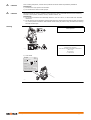
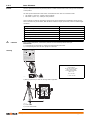
GeoMax Zipp20 Series User Manual Version 1.1 English Introduction Purchase Congratulations on the purchase of a GeoMax Zipp20 series instrument. This manual contains important safety directions as well as instructions for setting up the product and operating it. Refer to "1 Safety Directions" for further information. Read carefully through the User Manual before you switch on the product. Product identification The type and serial number of your product are indicated on the type plate. Always refer to this information when you contact your agency or GeoMax authorised service workshop. Trademarks • Windows is a registered trademark of Microsoft Corporation in the United States and other countries All other trademarks are the property of their respective owners. Validity of this manual Description General This manual applies to Zipp20 instruments. Where there are differences between the models they are clearly described. The appearance of the products is subject to change without notice. The appearance of the actual product may vary slightly from the product shown in the illustrations. Telescope • • Measuring with P modes: When measuring distances to a reflector with Electronic Distance Measurement (EDM) mode “P”, the telescope uses a wide visible red laser beam, which emerges coaxially from the objective of telescope. Measuring with NP modes: Instruments that are equipped with a reflectorless EDM additionally offer the EDM mode “NP”. When measuring distances with this EDM mode, the telescope uses a narrow visible red laser beam, which emerges coaxially from the objective of telescope. WARNING 003839_001 Do NOT remove the battery during operation of the instrument, or during the shutdown procedure. This can result in a file system error and data loss! Always switch off the instrument by pressing the On/Off key, and wait until the instrument has shutdown completely before removing the battery. Introduction Zipp20 | 2 Table of Contents In this manual Chapter 1 Safety Directions 1.1 1.2 1.3 1.4 1.5 1.6 1.7 1.8 1.9 2 6 6.2 6.3 7 Work Settings Regional Settings Screen Settings EDM Settings Communication Settings 22 22 23 24 25 26 Calibration 6.1.1 Overview 6.1.2 Preparation 6.1.3 Calibrating Line-of-Sight, Vertical Index Error and Compensator Index Error 6.1.4 Calibrating the Level of the Instrument and Tribrach 6.1.5 Inspecting the Laser Plummet of the Instrument 6.1.6 Servicing the Tripod System Information Loading Software Working with a USB Memory Stick Working with Bluetooth Care and Transport 8.1 8.2 8.3 9 18 18 19 20 20 21 Working with interfaces 7.1 7.2 8 Instrument Setup Working with the Battery Main Menu Survey Application Distance Measurements - Guidelines for Correct Results Tools 6.1 Transport Storage Cleaning and Drying Technical Data 9.1 9.2 Table of Contents 13 13 13 13 15 15 15 16 16 17 Settings 5.1 5.2 5.3 5.4 5.5 5 5 5 6 6 6 7 7 8 8 10 11 11 12 Keyboard Screen Status Icons Softkeys Operating Principles Operation 4.1 4.2 4.3 4.4 4.5 5 System Components Container Contents Instrument Components User Interface 3.1 3.2 3.3 3.4 3.5 4 General Definition of Use Limits of Use Responsibilities Hazards of Use Laser Classification 1.6.1 General 1.6.2 Distancer, Measurements with Reflectors 1.6.3 Distancer, Measurements without Reflectors (NP mode) 1.6.4 Laser Plummet Electromagnetic Compatibility EMC FCC Statement, Applicable in U.S. ICES-003 Statement, Applicable in Canada Description of the System 2.1 2.2 2.3 3 Page Angle Measurement Distance Measurement with Reflectors 27 27 27 27 27 29 29 30 30 30 31 31 31 32 32 32 32 33 33 33 Zipp20 | 3 9.3 9.4 9.5 9.6 9.7 Distance Measurements without Reflectors (Reflectorless mode) Conformity to National Regulations 9.4.1 Zipp20 9.4.2 Internal battery ZBA301 General Technical Data of the Instrument Scale Correction Reduction Formulas 33 34 34 34 35 36 37 10 Software Licence Agreement 38 11 Glossary 39 Appendix A Menu Tree 41 Appendix B Directory Structure 42 Table of Contents Zipp20 | 4 1 Safety Directions 1.1 General Description The following directions enable the person responsible for the product, and the person who actually uses the equipment, to anticipate and avoid operational hazards. The person responsible for the product must ensure that all users understand these directions and adhere to them. About Warning Messages Warning messages are an essential part of the safety concept of the instrument. They appear wherever hazards or hazardous situations can occur. Warning messages... • make the user alert about direct and indirect hazards concerning the use of the product. • contain general rules of behaviour. For the users‘ safety, all safety instructions and safety messages shall be strictly observed and followed! Therefore, the manual must always be available to all persons performing any tasks described herein. DANGER, WARNING, CAUTION and NOTICE are standardized signal words for identifying levels of hazards and risks related to personal injury and property damage. For your safety it is important to read and fully understand the table below with the different signal words and their definitions! Supplementary safety information symbols may be placed within a warning message as well as supplementary text. Type Description DANGER Indicates an imminently hazardous situation which, if not avoided, will result in death or serious injury. WARNING Indicates a potentially hazardous situation or an unintended use which, if not avoided, could result in death or serious injury. CAUTION Indicates a potentially hazardous situation or an unintended use which, if not avoided, may result in minor or moderate injury. NOTICE 1.2 Indicates a potentially hazardous situation or an unintended use which, if not avoided, may result in appreciable material, financial and environmental damage. Important paragraphs which must be adhered to in practice as they enable the product to be used in a technically correct and efficient manner. Definition of Use Intended use • • • • • • Measuring horizontal and vertical angles. Measuring distances. Recording measurements. Visualizing the aiming direction and vertical axis. Data communication with external appliances. Computing by means of software. Reasonably forseeable misuse • • • • • Use of the product without instruction. Use outside of the intended use and limits. Disabling safety systems. Removal of hazard notices. Opening the product using tools, for example screwdriver, unless this is specifically permitted for certain functions. Modification or conversion of the product. Use after misappropriation. Use of products with obviously recognisable damages or defects. Use with accessories from other manufacturers without the prior explicit approval of GeoMax. Aiming directly into the sun. Inadequate safeguards at the working site. Deliberate dazzling of third parties. Controlling of machines, moving objects or similar monitoring application without additional controland safety installations. • • • • • • • • Safety Directions Zipp20 | 5 1.3 Limits of Use Environment Suitable for use in an atmosphere appropriate for permanent human habitation: not suitable for use in aggressive or explosive environments. Local safety authorities and safety experts must be contacted before working in hazardous areas, or close to electrical installations or similar situations by the person in charge of the product. DANGER 1.4 Responsibilities Manufacturer of the product GeoMax AG, CH-9443 Widnau, hereinafter referred to as GeoMax, is responsible for supplying the product, including the user manual and original accessories, in a safe condition. Person responsible for the product The person responsible for the product has the following duties: • To understand the safety instructions on the product and the instructions in the user manual. • To ensure that it is used in accordance with the instructions. • To be familiar with local regulations relating to safety and accident prevention. • To inform GeoMax immediately if the product and the application becomes unsafe. • To ensure that the national laws, regulations and conditions for the operation of e.g. radio transmitters or lasers are respected. 1.5 Hazards of Use CAUTION Watch out for erroneous measurement results if the product has been dropped or has been misused, modified, stored for long periods or transported. Precautions: Periodically carry out test measurements and perform the field adjustments indicated in the user manual, particularly after the product has been subjected to abnormal use and before and after important measurements. DANGER Because of the risk of electrocution, it is dangerous to use poles and extensions in the vicinity of electrical installations such as power cables or electrical railways. Precautions: Keep at a safe distance from electrical installations. If it is essential to work in this environment, first contact the safety authorities responsible for the electrical installations and follow their instructions. CAUTION Be careful when pointing the product towards the sun, because the telescope functions as a magnifying glass and can injure your eyes and/or cause damage inside the product. Precautions: Do not point the product directly at the sun. WARNING During dynamic applications, for example stakeout procedures there is a danger of accidents occurring if the user does not pay attention to the environmental conditions around, for example obstacles, excavations or traffic. Precautions: The person responsible for the product must make all users fully aware of the existing dangers. WARNING Inadequate securing of the working site can lead to dangerous situations, for example in traffic, on building sites, and at industrial installations. Precautions: Always ensure that the working site is adequately secured. Adhere to the regulations governing safety and accident prevention and road traffic. CAUTION If the accessories used with the product are not properly secured and the product is subjected to mechanical shock, for example blows or falling, the product may be damaged or people can sustain injury. Precautions: When setting-up the product, make sure that the accessories are correctly adapted, fitted, secured, and locked in position. Avoid subjecting the product to mechanical stress. Safety Directions Zipp20 | 6 WARNING If the product is used with accessories, for example masts, staffs, poles, you may increase the risk of being struck by lightning. Precautions: Do not use the product in a thunderstorm. WARNING During the transport, shipping or disposal of batteries it is possible for inappropriate mechanical influences to constitute a fire hazard. Precautions: Before shipping the product or disposing of it, discharge the batteries by running the product until they are flat. When transporting or shipping batteries, the person in charge of the product must ensure that the applicable national and international rules and regulations are observed. Before transportation or shipping contact your local passenger or freight transport company. WARNING High mechanical stress, high ambient temperatures or immersion into fluids can cause leakage, fire or explosions of the batteries. Precautions: Protect the batteries from mechanical influences and high ambient temperatures. Do not drop or immerse batteries into fluids. WARNING If battery terminals are short circuited e.g. by coming in contact with jewellery, keys, metalized paper or other metals, the battery can overheat and cause injury or fire, for example by storing or transporting in pockets. Precautions: Make sure that the battery terminals do not come into contact with metallic objects. WARNING If the product is improperly disposed of, the following can happen: • If polymer parts are burnt, poisonous gases are produced which may impair health. • If batteries are damaged or are heated strongly, they can explode and cause poisoning, burning, corrosion or environmental contamination. • By disposing of the product irresponsibly you may enable unauthorised persons to use it in contravention of the regulations, exposing themselves and third parties to the risk of severe injury and rendering the environment liable to contamination. • Improper disposal of silicone oil may cause environmental contamination. Precautions: The product must not be disposed with household waste. Dispose of the product appropriately in accordance with the national regulations in force in your country. Always prevent access to the product by unauthorised personnel. Product-specific treatment and waste management information is available from GeoMax AG. WARNING Only GeoMax authorised service workshops are entitled to repair these products. 1.6 Laser Classification 1.6.1 General General The following chapters provide instructions and training information about laser safety according to international standard IEC 60825-1 (2007-03) and technical report IEC TR 60825-14 (2004-02). The information enables the person responsible for the product and the person who actually uses the equipment, to anticipate and avoid operational hazards. Safety Directions According to IEC TR 60825-14 (2004-02), products classified as laser class 1, class 2 and class 3R do not require: • laser safety officer involvement, • protective clothes and eyewear, • special warning signs in the laser working area if used and operated as defined in this User Manual due to the low eye hazard level. National laws and local regulations could impose more stringent instructions for the safe use of lasers than IEC 60825-1 (2007-03) and IEC TR 60825-14 (2004-02). Zipp20 | 7 1.6.2 General Distancer, Measurements with Reflectors The EDM module built into the product produces a visible laser beam which emerges from the telescope objective. The product described in this section is classified as laser class 1 in accordance with: • IEC 60825-1 (2007-03): "Safety of laser products" • EN 60825-1 (2007-10): "Safety of laser products" These products are safe under reasonably foreseeable conditions of operation and are not harmful to the eyes provided that the products are used and maintained in accordance with this User Manual. Description Value Maximum average radiant power 0.33 mW Pulse duration 800 ps Pulse repetition frequency (PRF) 100 MHz - 150 MHz Wavelength 650 nm - 690 nm Beam divergance 1.5 mrad x 3 mrad Labelling Class 1 Laser Product according to IEC 60825-1 (2007 - 03) Type: Zipp20 Art.No.: XXXXXX Power: 7.4V ---, 1.4A max. GeoMax AG CH-9443 Widnau S.No.: Manufactured: 20XX Made in China XXXXXX Complies with FDA performance standards for laser products except for deviations pursuant to Laser Notice No. 50, dated June 24, 2007. This device complies with part 15 of the FCC Rules. Operation is subject to the following two conditions: (1) This device may not cause harmful interference, and (2) this device must accept any interference received, including interference that may cause undesired operation. a 007382_001 a) Laser beam 1.6.3 General Distancer, Measurements without Reflectors (NP mode) The EDM module built into the product produces a visible laser beam which emerges from the telescope objective. The laser product described in this section is classified as laser class 3R in accordance with: • IEC 60825-1 (2007-03): "Safety of laser products" • EN 60825-1 (2007-10): "Safety of laser products" Direct intrabeam viewing may be hazardous (low eye hazard level), in particular for deliberate ocular exposure. The beam may cause dazzle, flash-blindness and after-images, particularly under low ambient light conditions. The risk of injury for laser class 3R products is limited because of: a) unintentional exposure would rarely reflect worst case conditions of (e.g.) beam alignment with the pupil, worst case accommodation, b) inherent safety margin in the maximum permissible exposure to laser radiation (MPE) c) natural aversion behaviour for exposure to bright light for the case of visible radiation. Description Value Maximum average radiant power 5.00 mW Pulse duration 800 ps Pulse repetition frequency 100 MHz - 150 MHz Wavelength 650 nm - 690 nm Beam divergence 0.2 mrad x 0.3 mrad NOHD (Nominal Ocular Hazard Distance) @ 0.25 s 80 m / 262 ft Safety Directions Zipp20 | 8 CAUTION From a safety perspective, class 3R laser products should be treated as potentially hazardous. Precautions: 1) Prevent direct eye exposure to the beam. 2) Do not direct the beam at other people. CAUTION Potential hazards are not only related to direct beams but also to reflected beams aimed at reflecting surfaces such as prisms, windows, mirrors, metallic surfaces, etc. Precautions: 1) Do not aim at areas that are essentially reflective, such as a mirror, or which could emit unwanted reflections. 2) Do not look through or beside the optical sight at prisms or reflecting objects when the laser is switched on, in laser pointer or distance measurement mode. Aiming at prisms is only permitted when looking through the telescope. Labelling Laser Aperture a Laser Radiation Avoid direct eye exposure Class 3R Laser Product according to IEC 60825-1 (2007 - 03) 003862_001 Po 5.00 mW = 650-690 nm a) Laser beam Type: Zipp20 Art.No.: XXXXXX Power: 7.4V ---, 1.4A max. GeoMax AG CH-9443 Widnau S.No.: Manufactured: 20XX Made in China XXXXXX Complies with FDA performance standards for laser products except for deviations pursuant to Laser Notice No. 50, dated June 24, 2007. This device complies with part 15 of the FCC Rules. Operation is subject to the following two conditions: (1) This device may not cause harmful interference, and (2) this device must accept any interference received, including interference that may cause undesired operation. a 007382_001 Safety Directions Zipp20 | 9 1.6.4 Laser Plummet General The laser plummet built into the product produces a visible red laser beam which emerges from the bottom of the product. The laser product described in this section is classified as laser class 2 in accordance with: • IEC 60825-1 (2007-03): "Safety of laser products" • EN 60825-1 (2007-10): "Safety of laser products" These products are safe for momentary exposures but can be hazardous for deliberate staring into the beam. The beam may cause dazzle, flash-blindness and after-images, particularly under low ambient light conditions. CAUTION Labelling Description Value Maximum average radiant power 1.5 mW Duty cycle 14%, 22%, 35%, 70% Wavelength 635 nm Pulse repetition frequency 1 kHz Beam divergence < 1.5 mrad Beam diameter at aperture (1/e) 2.0 mm x 1.5 mm From a safety perspective, class 2 laser products are not inherently safe for the eyes. Precautions: 1) Avoid staring into the beam or viewing it through optical instruments. 2) Avoid pointing the beam at other people or at animals. Type: Zipp20 Art.No.: XXXXXX Power: 7.4V ---, 1.4A max. GeoMax AG CH-9443 Widnau S.No.: XXXXXX Manufactured: 20XX Made in China Complies with FDA performance standards for laser products except for deviations pursuant to Laser Notice No. 50, dated June 24, 2007. This device complies with part 15 of the FCC Rules. Operation is subject to the following two conditions: (1) This device may not cause harmful interference, and (2) this device must accept any interference received, including interference that may cause undesired operation. Laser Radiation Do not stare into the beam Class 2 Laser Product according to IEC 60825-1 (2007 - 03) Po 1.00 mW = 620 - 690 nm a 007383_001 a) Will be replaced by a class 3R warning label if applicable b a 003864_001 a) Laser beam b) Exit for laser beam Safety Directions Zipp20 | 10 1.7 Electromagnetic Compatibility EMC Description The term Electromagnetic Compatibility is taken to mean the capability of the product to function smoothly in an environment where electromagnetic radiation and electrostatic discharges are present, and without causing electromagnetic disturbances to other equipment. Electromagnetic radiation can cause disturbances in other equipment. WARNING Although the product meets the strict regulations and standards which are in force in this respect, GeoMax cannot completely exclude the possibility that other equipment may be disturbed. CAUTION There is a risk that disturbances may be caused in other equipment if the product is used with accessories from other manufacturers, for example field computers, personal computers or other electronic equipment, non-standard cables or external batteries. Precautions: Use only the equipment and accessories recommended by GeoMax. When combined with the product, they meet the strict requirements stipulated by the guidelines and standards. When using computers or other electronic equipment, pay attention to the information about electromagnetic compatibility provided by the manufacturer. CAUTION Disturbances caused by electromagnetic radiation can result in erroneous measurements. Although the product meets the strict regulations and standards which are in force in this respect, GeoMax cannot completely exclude the possibility that the product may be disturbed by intense electromagnetic radiation, for example, near radio transmitters, two-way radios or diesel generators. Precautions: Check the plausibility of results obtained under these conditions. CAUTION If the product is operated with connecting cables attached at only one of their two ends, for example external supply cables, interface cables, the permitted level of electromagnetic radiation may be exceeded and the correct functioning of other products may be impaired. Precautions: While the product is in use, connecting cables, for example product to external battery, product to computer, must be connected at both ends. WARNING Electromagnetic fields can cause disturbances in other equipment, in installations, in medical devices, for example pacemakers or hearing aids and in aircraft. It can also affect humans and animals. Precautions: Although the product meets the strict regulations and standards which are in force in this respect, GeoMax cannot completely exclude the possibility that other equipment can be disturbed or that humans or animals can be affected. • • • 1.8 Do not operate the product with radio or digital cellular phone devices in the vicinity of filling stations or chemical installations, or in other areas where an explosion hazard exists. Do not operate the product with radio or digital cellular phone devices near to medical equipment. Do not operate the product with radio or digital cellular phone devices in aircraft. FCC Statement, Applicable in U.S. WARNING This equipment has been tested and found to comply with the limits for a Class B digital device, pursuant to part 15 of the FCC rules. These limits are designed to provide reasonable protection against harmful interference in a residential installation. This equipment generates, uses and can radiate radio frequency energy and, if not installed and used in accordance with the instructions, may cause harmful interference to radio communications. However, there is no guarantee that interference will not occur in a particular installation. If this equipment does cause harmful interference to radio or television reception, which can be determined by turning the equipment off and on, the user is encouraged to try to correct the interference by one or more of the following measures: • Reorient or relocate the receiving antenna. • Increase the separation between the equipment and the receiver. • Connect the equipment into an outlet on a circuit different from that to which the receiver is connected. • Consult the dealer or an experienced radio/TV technician for help. WARNING Changes or modifications not expressly approved by GeoMax for compliance could void the user's authority to operate the equipment. Safety Directions Zipp20 | 11 Labelling Zipp20 Type: Zipp20 Art.No.: XXXXXX Power: 7.4V ---, 1.4A max. GeoMax AG CH-9443 Widnau S.No.: Manufactured: 20XX Made in China XXXXXX Complies with FDA performance standards for laser products except for deviations pursuant to Laser Notice No. 50, dated June 24, 2007. This device complies with part 15 of the FCC Rules. Operation is subject to the following two conditions: (1) This device may not cause harmful interference, and (2) this device must accept any interference received, including interference that may cause undesired operation. 007384_001 Labelling internal battery ZBA301 This device complies with part 15 of the FCC Rules. Operation is subject to the following two conditions: (1) This device may not cause harmful interference, and (2) this device must accept any interference received, including interference that may cause undesired operation. 003675_001 1.9 ICES-003 Statement, Applicable in Canada WARNING This Class (B) digital apparatus complies with Canadian ICES-003. Cet appareil numérique de la classe (B) est conforme à la norme NMB-003 du Canada. Safety Directions Zipp20 | 12 2 Description of the System 2.1 System Components Main components Component Description Zipp20 instrument An instrument for measuring data. Ideally suited for tasks from simple surveys to complex applications. Firmware 2.2 The firmware package installed on the instrument. Consists of a standard base operating system. Container Contents Container contents a g b h d c i e j f k 005937_001 2.3 a) b) c) d) e) f) g) h) i) j) k) ZCH301 battery charger Instrument with supplied tribrach Plumb bob ZDC301 USB cable Power cable for battery charger Manual Adjustment tools USB memory stick ZBA301 battery Adapter for charger Protective cover Instrument Components Instrument components part 1 of 2 a 003841_001 b e Description of the System c d f g a) Detachable carrying handle with mounting screw b) Optical sight c) Objective with integrated Electronic Distance Measurement (EDM). Exit for EDM laser beam d) Vertical drive e) Compartment for USB cable port and USB host port f) Leveling bubble g) Keyboard Zipp20 | 13 Instrument components part 2 of 2 b a 003872_001 c d e f Description of the System g a) b) c) d) e) f) g) Focusing telescope image Eyepiece; focusing graticule Battery cover Horizontal drive Foot screw Display Keyboard Zipp20 | 14 3 User Interface 3.1 Keyboard Alphanumeric keyboard a b c d e f g 007380_001 Keys Key a) b) c) d) e) f) g) Alphanumeric keypad FNC2 key FNC1 key ESC key Navigation key ON key / ENTER key Function keys F1 to F4 Description Alphanumeric keypad for entry of text and numerical values. ON key. Turns instrument on. ENTER key. Confirms an entry and continues to the next field when pressed for 1 s. FNC1 key. Quick-access to measurement supporting functions. FNC2 key. Page key. Displays the next screen when several screens are available. ESC key. Quits a screen or edit mode without saving changes. Returns to next higher level. Navigation key. Controls the focus bar within the screen and the entry bar within a field. Function keys that are assigned the variable functions displayed at the bottom of the screen. 3.2 Screen Screen a b c d e 007386_001_en User Interface a) b) c) d) e) Status icons Title of screen Focus in screen. Active field Fields Softkeys All shown screens are examples. It is possible that local firmware versions are different to the basic version. Zipp20 | 15 3.3 Status Icons Description The icons provide status information related to basic instrument functions. Depending on the firmware version, different icons may be displayed. Icons Icon Description The battery symbol indicates the level of the remaining battery capacity, 75% full shown in the example. Tap the icon to open the SYSTEM INFO screen. Compensator is on. Tap the icon to open the Level Up screen. Compensator is off. Tap the icon to open the Level Up screen. IR EDM mode for measuring to prisms and reflective targets. Tap the icon to open the EDM SETTINGS screen. RL EDM mode for measuring to all targets. Tap the icon to open the EDM SETTINGS screen. Keypad is set to numeric mode. Keypad is set to alphanumeric mode. Indicates that telescope position is face I. Tap the icon to open the Level Up screen. Indicates that telescope position is face II. Tap the icon to open the Level Up screen. Bluetooth is connected. If the icon is grey, the Bluetooth communication port is selected, but the status is inactive. If the icon is blue, the status is active. Tap the icon to open the COMMUNICATION SETTINGS screen. USB communication port is selected. Tap the icon to open the COMMUNICATION SETTINGS screen. RS232 communication port is selected. Tap the icon to open the COMMUNICATION SETTINGS screen. A double arrow indicates that a field has a selectable list. 3.4 Softkeys Description Softkeys are selected using the relevant F1 to F4 function key. This chapter describes the functionality of the common softkeys used by the system. The more specialised softkeys are described where they appear in the program chapters. Common softkey functions Key Description ALPH To change the keypad operation to alphanumerical. NUM. To change the keypad operation to numerical. BACK To return to the last active screen. EDM To view and change EDM settings. Refer to "5.4 EDM Settings". MEAS To start distance and angle measurements without saving the measured values. OK If entry screen: Confirms measured or entered values and continues the process. If message screen: Confirms message and continues with selected action or returns to the previous screen to reselect an option. DEFAULT To reset all editable fields to their default values. User Interface Zipp20 | 16 3.5 Operating Principles Turn instrument on Press the ON key. Turn instrument off Return to WinCE main screen. Tap on the Windows icon in task bar to shut down the Zipp20. Alphanumeric keypad The alphanumerical keypad is used to enter characters directly into editable fields. • Numeric fields: Can only contain numerical values. By pressing a key of the keypad the number will be displayed. • Alphanumeric fields: Can contain numbers and letters. By pressing a key of the keypad the first character written above that key will be displayed. By pressing several times you can toggle through the characters. For example: 1->S->T->U->1->S.... Edit fields ESC Deletes any change and restores the previous value. Moves the cursor to the left Moves the cursor to the right. Inserts a character at the cursor position. Deletes the character at the cursor position. Special characters In edit mode the position of the decimal place cannot be changed. The decimal place is skipped. Character Description +/- In the alphanumeric character set "+" and "-" are treated as normal alphanumeric characters with no mathematical function. “+” / “-” only appear in front of an entry. In this example selecting 3 on an alphanumeric keyboard would start Tools. User Interface Zipp20 | 17 4 Operation 4.1 Instrument Setup Description This topic describes an instrument setup over a marked ground point using the laser plummet. It is always possible to set up the instrument without the need for a marked ground point. Important features • It is always recommended to shield the instrument from direct sunlight and avoid uneven temperatures around the instrument. • The laser plummet described in this topic is built into the vertical axis of the instrument. It projects a red spot onto the ground, making it appreciably easier to centre the instrument. • The laser plummet cannot be used with a tribrach equipped with an optical plummet. Tripod When setting up the tripod pay attention to ensuring a horizontal position of the tripod plate. Slight corrections of inclination can be made with the foot screws of the tribrach. Larger corrections must be done with the tripod legs. Loosen the clamping screws on the tripod legs, pull out to the required length and tighten the clamps. a) In order to guarantee a firm foothold sufficiently press the tripod legs into the ground. b) When pressing the legs into the ground note that the force must be applied along the legs. a b Careful handling of tripod. • Check all screws and bolts for correct fit. • During transport always use the cover supplied. • Use the tripod only for surveying tasks. Setup step-by-step 7 2 3 6 1 1 1 5 5 4 5 03851_001 1 5 6 7 8 Extend the tripod legs to allow for a comfortable working posture. Position the tripod over the marked ground point, centring it as best as possible. Fasten the tribrach and instrument onto the tripod. Turn on the instrument, and, if tilt correction is set on, the laser plummet activates automatically, and the Level up screen appears. Otherwise, tap on Level/Face icon in status bar. Move the tripod legs (1) and use the tribrach footscrews (6) to center the plummet (4) over the ground point. Adjust the tripod legs (5) to level the tubular level (7). Use the electronic level and turn the tribrach footscrews (6) to level the instrument precisely. Center the instrument precisely over the ground point by shifting the tribrach on the tripod plate (2). Repeat steps 6 and 7 until the required accuracy is achieved. Operation Zipp20 | 18 2 3 4 Level up with the electronic level step-by-step The electronic level can be used to level up the instrument precisely by using the footscrews of the tribrach. 1 2 3 4 5 Turn the instrument until the tubular level is parallel to two footscrews. Center the level on the instrument approximately by turning the footscrews of the tribrach. Turn on the instrument, and, if tilt correction is set on, the laser plummet activates automatically, and the Level up screen appears. Otherwise, tap on Level/Face icon in status bar. Center the electronic level for the first axis by turning the two footscrews. Center the electronic level for the second axis by turning the last footscrew. When the electronic level is centered and both axes are within the tolerance limit, the instrument has been levelled up. 6 Accept with OK. Under some circumstances the laser dot is not visible, for example over pipes. In this case, using a transparent plate enables the laser dot to be seen and then easily aligned to the center of the pipe. Position over pipes or holes 003853_001 4.2 Working with the Battery Charging / first-time use • • • • • The battery must be charged prior to using it for the first time because it is delivered with an energy content as low as possible. The permissible temperature range for charging is between 0°C to +40°C/+32°F to +104°F. For optimal charging we recommend charging the batteries at a low ambient temperature of +10°C to +20°C/+50°F to +68°F if possible. It is normal for the battery to become warm during charging. Using the chargers recommended by GeoMax, it is not possible to charge the battery if the temperature is too high. For new batteries or batteries that have been stored for a long time (> three months), it is effectual to make only one charge/discharge cycle. For Li-Ion batteries, a single discharging and charging cycle is sufficient. We recommend carrying out the process when the battery capacity indicated on the charger or on a GeoMax product deviates significantly form the actual battery capacity available. Change the battery step-by-step Remove the battery holder from the instrument (1). Remove the battery from the battery holder (2). 2 1 003854_001 Insert the new battery into the battery holder (3), ensuring that the contacts are facing outward. The battery should click into position. 3 Insert the battery holder back into the battery compartment (4). 4 003855_001 Operation Zipp20 | 19 4.3 Description Main Menu The MAIN MENU is the starting place for accessing most functionality of the instrument. It is displayed when selecting the Zipp20 basic application from the WinCE main screen. MAIN MENU Description of the MAIN MENU functions 4.4 Function Description 1 Survey To select and start the survey application. Refer to "4.4 Survey Application". 2 Settings To select and start Settings. Refer to "5 Settings". 3 Tools To select and start Tools. Refer to "6 Tools". 4 EXIT To exit Zipp20 Basic application. Survey Application Description The Survey application can be used to take immediately measurements. Access Select Survey from the MAIN MENU. Survey Survey softkeys The following softkeys are displayed on the Survey screen. Softkey Description MEAS Trigger measurement. EDM Enter EDM Settings. SET Enter target height hr and station height hi. H.A. = 0 Set horizontal angle to 0. Operation Zipp20 | 20 4.5 Distance Measurements - Guidelines for Correct Results Description A laser distancer (EDM) is incorporated into the Zipp20 instruments. In all versions, the distance can be determined by using a visible red laser beam which emerges coaxially from the telescope objective. There are two EDM modes: • Prism measurements (P) • Reflectorless measurements (NP) • When a distance measurement is triggered, the EDM measures to the object which is in the beam path at that moment. If a temporary obstruction, for example a passing vehicle, heavy rain, fog or snow is between the instrument and the point to be measured, the EDM may measure to the obstruction. Be sure that the laser beam is not reflected by anything close to the line of sight, for example highly reflective objects. Avoid interrupting the measuring beam while taking reflectorless measurements or measurements using reflective foils. Do not measure with two instruments to the same target simultaneously. NP measurements • • • P measurements • • • • • Red laser to reflector foil • • Operation Accurate measurements to prisms should be made in P-Standard mode. Measurements to strongly reflecting targets such as traffic lights in Prism mode without a prism should be avoided. The measured distances may be wrong or inaccurate. When a distance measurement is triggered, the EDM measures to the object which is in the beam path at that moment. If for example people, cars, animals, or swaying branches cross the laser beam while a measurement is being taken, a fraction of the laser beam is reflected from these objects and may lead to incorrect distance values. Measurements to prisms are only critical if an object crosses the measuring beam at a distance of 0 to 30 m and the distance to be measured is more than 300 m. In practice, because the measuring time is very short, the user can always find a way of avoiding unwanted objects from interfering in the beam path. The visible red laser beam can also be used to measure to reflective foils. To guarantee the accuracy the red laser beam must be perpendicular to the reflector foil and it must be well adjusted. Make sure the additive constant belongs to the selected target (reflector). Zipp20 | 21 5 Settings 5.1 Work Settings Access 1) Select Settings from the MAIN MENU. 2) Select Work from the SETTINGS menu. Work settings Field Description Tilt Corr. Tilting compensation deactivated. Two-axis compensation. Vertical angles refer to the plummet line and the horizontal directions are corrected by the standing axis tilt. For corrections depending on the H.A. Corr. setting, refer to the table "Tilt and horizontal corrections". If the instrument is used on an unstable base, for example a shaking platform or ship, the compensator should be deactivated. The deactivation avoids the compensator drifting out of its measuring range and interrupting the measuring process by indicating an error. H.A. Corr. Tilt and horizontal corrections OFF ON ON Horizontal corrections are activated. For normal operation, the horizontal correction should remain active. Each measured horizontal angle is corrected, depending on the vertical angle. For corrections depending on the Tilt Corr. setting, refer to the table Tilt and horizontal corrections . Setting Settings Correction Tilt correction Horizontal correction Incline longitu- Incline transdinal versal Horizontal collimation Tilting axis Off On No No Yes Yes On On Yes Yes Yes Yes Off Off No No No No On Off Yes No No No Zipp20 | 22 Regional Settings Access 1) Select Settings from the MAIN MENU. 2) Select Regional from the SETTINGS menu. Regional settings Field Description H.A. Incr. Right Set horizontal angle to clockwise direction measurement. Left Set horizontal angle to counter-clockwise direction measurement. Counter-clockwise directions are displayed but are saved as clockwise directions. V.A. Setting Sets the vertical angle. Zenith 45° 0° Zenith = 0°; Horizon = 90°. 90° 0° 27 ° 180 TSOX_018 Horizon 5° ° +90 +4 0° ° - 90 TSOX_019 Slope % 71° --.--% 34” Slope [%] +300 % +100% 20° 360s gon n go 0 -5 ,5 gon -79 --.--% Zenith = 90°; Horizon = 0°. Vertical angles are positive above the horizon and negative below it. ° -45 ° 180 45 ° 5.2 +18 % 0° ±V 45°=100%; Horizon = 0°. Vertical angles are expressed in % with positive above the horizon and negative below it. The % value increases rapidly. --.% appears on the display above 300%. -100 % -300 % TSOX_020 Language Sets the chosen language. Several languages can be uploaded onto the instrument. The current loaded language or languages are shown. Lang. Choice If multiple languages are loaded, a screen to choose the language can be shown directly after switching on the instrument. Angle Unit Min. Reading On The language screen is shown as the startup screen. Off The language screen is not shown as the startup screen. Sets the units shown for all angular fields. °'" Degree sexagesimal. Possible angle values: 0° to 359°59'59'' gon Gon. Possible angle values: 0 to 399.999 gon dec. deg Degree decimal. Possible angle values: 0° to 359.999° mil Mil. Possible angle values: 0 to 6399.99 mil. The setting of the angle units can be changed at any time. The current displayed values are converted according to the selected unit. Sets the number of decimal places shown for all angular fields. This setting is for data display and does not apply to data export or storage. °'" Settings (0° 00' 0.1"/0° 00' 01"/0° 00' 05"/ 0° 00' 10") gon (0.0001 / 0.0005 / 0.001) dec. deg (0.0001 / 0.0005 / 0.001) mil (0.01 / 0.05 / 0.1) Zipp20 | 23 Field Description Dist. Unit Sets the units shown for all distance and coordinate related fields. Temp. Unit Press. Unit Time (24h) 5.3 meter Metres [m]. US-ft US feet [ft]. INT-ft International feet [fi]. ft-in/16 US feet-inch-1/16 inch [ft]. Sets the units shown for all temperature fields. °C Degree Celsius. °F Degree Fahrenheit. Sets the units shown for all pressure fields. hPa Hecto Pascal. mbar Millibar. mmHg Millimeter mercury. inHg Inch mercury. The current time. Date Shows an example of the selected date format. Format dd.mm.yyyy, mm.dd.yyyy or yyyy.mm.dd How the date is shown in all date-related fields. Screen Settings Access 1) Select Settings from the MAIN MENU. 2) Select Screen from the SETTINGS menu. Screen settings Field Description Screen Ill. Off to 100% Sets the display illumination in 20% steps. Cross. Ill. Sets the reticle illumination in three available steps: Low/Medium/High. Touch Screen On The touch screen is activated. Off The touch screen is deactivated. Auto-Off Beep Sector Beep Press Calib. to calibrate the touch screen.Follow the instructions on the screen. Enable The instrument switches off after 20 minutes without any activity, for example no key pressed or vertical and horizontal angle deviation is ±3". Disable Automatic switch-off is deactivated. Battery discharges quicker. The beep is an acoustic signal after each key stroke. Normal Normal volume. Loud Increased volume. Off Beep is deactivated. On Sector beep sounds at right angles (0°, 90°, 180°, 270° or 0, 100, 200, 300 gon). 1)No beep. 2)Fast beep; from 95.0 to 99.5 gon and 105.0 to 100.5 gon. 3)Permanent beep; from 99.5 to 99.995 gon and from 100.5 to 100.005 gon. 90° 1 3 2 1 0° 3 2 1 180° TSOX_094 Off Settings Sector beep is deactivated. Zipp20 | 24 5.4 EDM Settings Description The settings on this screen define the active EDM, Electronic Distance Measurement. Different settings for measurements are available with Reflectorless (RL) and Prism (IR) EDM modes. Access 1) Select Settings from the MAIN MENU. 2) Select EDM from the SETTINGS menu. EDM SETTINGS ATMOS To enter atmospheric data ppm. PPM To enter an individual ppm value. SCALE To enter projection scale details. SIGNAL To view EDM Signal reflection value. FREQ. To view the EDM frequency. Field Description Mode IR-Default Fine measuring mode for high precision measurements with prisms. IR-Quick Quick measuring mode with prisms, with higher measuring speed and reduced accuracy. IR-Continuous For continuous distance measurements with prisms. Foil For distance measurements using Retro reflective targets. RL-Default For distance measurements without prisms. RL-Continuous For continuous distance measurements without prisms. Type ATMOSPHERIC DATA ENTRY Settings ZPR100 Abs. Const.: -34.4 mm Custom The user can define their own prism. Constants can be entered in mm in Abs. Const. Mini ZMP100 Abs. Const.: -16.9 mm JPMini ZPM100 Abs. Const.: 0.0 mm 360° GRZ4 Abs. Const.: -11.3 mm 360°Mini GRZ101 Abs. Const.: -4.4 mm Foil ZTM100 Abs. Const.: 0.0 mm None RL-modes Abs. Const.: 0.0 mm Abs. Const. This field displays the GeoMax prism constant for the selected Type. When Type is Custom this field becomes editable to set a user defined constant. Input can only be made in mm. Limit value: -999.9 mm to +999.9 mm. Laser-Beam Off Visible laser beam is deactivated. On Visible laser beam for visualising the target point is activated. This screen enables the entry of atmospheric parameters. Distance measurement is influenced directly by the atmospheric conditions of the air in which the measurements are taken. In order to take these influences into consideration distance measurements are corrected using atmospheric correction parameters. The refraction correction is taken into account in the calculation of the height differences and the horizontal distance. Refer to "9.6 Scale Correction" for the application of the values entered in this screen. PROJECTION SCALE Circular When PPM=0 is selected, the GeoMax standard atmosphere of 1013.25 mbar, 12°C, and 60% relative humidity will be applied. This screen enables entry of the scale of projection. Coordinates are corrected with the PPM parameter. Refer to "9.6 Scale Correction" for the application of the values entered in this screen. Zipp20 | 25 Free-PPM Entry This screen enables the entry of individual scaling factors. Coordinates and distance measurements are corrected with the PPM parameter. Refer to "9.6 Scale Correction" for the application of the values entered in this screen. EDM SIGNAL REFLECTION This screen tests the EDM signal strength (reflection strength) in steps of 1%. Enables optimal aiming at distant, barely visible, targets. A percentage bar and a beeping sound, indicate the reflection strength. The faster the beep the stronger the reflection. 5.5 Communication Settings Description For data transfer the communication parameters of the instrument must be set. Access 1) Select Settings from the MAIN MENU. 2) Select Comm from the SETTINGS menu. COMMUNICATION SETTINGS BTCode The default Bluetooth code is ‘0000‘. Field Description Port Instrument port. Bluetooth RS232 Communication is by the serial interface. Only for service purpose. USB Communication is by the USB host port. Bluetooth Communication is by Bluetooth. On Bluetooth sensor is activated. Off Bluetooth sensor is deactivated. The following fields are active only when Port: RS232 is set. Field Description Baudrate Speed of data transfer from receiver to device in bits per second. 1200, 2400, 4800, 9600, 14400, 19200, 38400, 57600, 115200, Topcon, Sokkia Databits Parity Endmark Stopbits Settings Number of bits in a block of digital data. 7 Data transfer is realised with 7 databits. 8 Data transfer is realised with 8 databits. Even Even parity. Available if data bit is set to 7. Odd Odd parity. Available if data bit is set to 7. None No parity. Available if data bit is set to 8. CR/LF The terminator is a carriage return followed by a line feed. CR The terminator is a carriage return. 1 Number of bits at the end of a block of digital data. Zipp20 | 26 6 Tools 6.1 Calibration 6.1.1 Overview Description GeoMax instruments are manufactured, assembled and adjusted to a high quality. Quick temperature changes, shock or stress can cause deviations and decrease the instrument accuracy. It is therefore recommended to calibrate the instrument from time to time. This can be done in the field by running through specific measurement procedures. The procedures are guided and have to be followed carefully and precisely as described in the following chapters. Some other instrument errors and mechanical parts can be adjusted mechanically. Electronic calibration The following instrument errors can be checked and calibrated electronically: • Horizontal collimation error, also called line-of-sight error. • Vertical index error, and simultaneously the compensator index error and the electronic level. For determining these errors, it is necessary to measure in both faces, but the procedure can be started in any face. Mechanical calibration The following instrument parts can be calibrated mechanically: • Level on the instrument and tribrach. • Laser plummet. • Screws on the tripod. During the manufacturing process, the instrument errors are carefully determined and set to zero. As mentioned, these errors can change and it is highly recommended to redetermine them in the following situations: • Before the instrument is used for the first time. • Before every high precision survey. • After rough or long periods of transport. • After long periods of work or storage. • If the temperature difference between current environment and the temperature at the last calibration is more than 10°C (18°F). 6.1.2 Preparation Before determining the instrument errors, level-up the instrument using the electronic level. The Level up is the first screen to appear after turning on the instrument. The tribrach, the tripod and the ground should be stable and secure from vibrations or other disturbances. The instrument should be protected from direct sunlight in order to avoid thermal expansion on one side only. Before starting to work, the instrument has to become acclimatised to the ambient temperature. Approximately two minutes per °C of temperature difference from storage to working environment, but at least 15 min, should be taken into account. 6.1.3 Calibrating Line-of-Sight, Vertical Index Error and Compensator Index Error Line-of-sight error The line-of-sight error, or horizontal collimation error is the deviation from the perpendicular between the tilting axis and the line of sight. The effect of the line-of-sight error to the horizontal direction increases with the vertical angle. c d b a 003856_001 Tools a) b) c) d) Tilting axis Line perpendicular to tilting axis Horizontal collimation, or line-of-sight, error Line-of-sight Zipp20 | 27 Vertical index error The vertical circle should read exactly 90° (100 gon) when the line of sight is horizontal. Any deviation from this figure is termed vertical index error. This is a constant error that affects all vertical angle readings. a d b c a) b) c) d) 003857_001 Compensator index error a Mechanical vertical axis of the instrument, also called standing axis Axis perpendicular to the vertical axis. True 90° Vertical angle is reading 90° Vertical index error By determining the vertical index error the electronic level is adjusted automatically b b c a d TSOX_141 a) b) c) d) Mechanical vertical axis of the instrument, also called standing axis Plumb line Longitudinal component (l) of the compensator index error Transversal component (t) of the compensator index error The compensator index errors (l, t) occur, if the vertical axis of the instrument and the plumb line are parallel but the zero points of the compensator and the circular level do not coincide. The calibration procedure electronically adjusts the zero point of the compensator. A longitudinal component in direction of the telescope and a transversal component perpendicular to the telescope define the plane of the dual axis compensator of the instrument. The longitudinal compensator index error (l) has a similar effect as the vertical index error and effects all vertical angle readings. The transversal compensator index error (t) is similar to the tilting axis error. The effect of this error to the horizontal angle readings is 0 at the horizon and increases with steep sightings. The vertical index error and the compensator index error are determined simultaneously. Access 1) Select Tools from the MAIN MENU. 2) Select Calibr. from the TOOLS menu. 3) Select a calibration option from the CALIBRATION screen. Calibration options In the CALIBRATION screen there are several calibration options. Menu selection Description HA-Collimation Refer to "6.1.3 Calibrating Line-of-Sight, Vertical Index Error and Compensator Index Error". Vertical Index Refer to "6.1.3 Calibrating Line-of-Sight, Vertical Index Error and Compensator Index Error". View Adjustment Data Displays the current calibration values that have been set for HA-Collimation and V-index. The procedures and conditions required to correct line-of-sight and vertical index errors are the same, therefore the procedure will only be described once. Tools Zipp20 | 28 6.1.4 Calibrating the Level of the Instrument and Tribrach Calibrate the level stepby-step 1 2 3 Place and secure the tribrach onto the tripod, and then secure the instrument onto the tribrach. Using the tribrach footscrews, level the instrument with the electronic level. To activate the electronic level, turn on the instrument, and, if tilt correction is set on, the Level up screen appears automatically. Alternatively, tap on the Level/Face icon in status bar. The bubbles of the instrument and tribrach levels must be centered. If one or both levels are not centered, adjust as follows. Instrument: If the bubble extends beyond the lines, use the Allen key supplied to center it with the adjustment screws. Tribrach: If the bubble extends beyond the circle, adjust it using the adjustment pin in conjunction with the adjustment screws. Turn the adjustment screws: • To the left: and the bubble approaches the screw. • To the right: and the bubble goes away from the screw. 4 Repeat step 3 on the instrument and tribrach until both levels are centered and no further adjustments are necessary. After the calibration, no adjustment screw should be loose. 6.1.5 Inspecting the Laser Plummet of the Instrument The laser plummet is integrated into the vertical axis of the instrument. Under normal conditions of use, the laser plummet does not need adjusting. If an adjustment is necessary due to external influences, the instrument has to be returned to a GeoMax service department. Inspect the laser plummet step-by-step 003860_001 1 2 Set up the instrument on the tripod approximately 1.5 m above the ground and level up. To activate the laser plummet, turn on the instrument, and, if tilt correction is set on, the laser plummet activates automatically, and the Level up screen appears. Otherwise, tap on the Level/Face icon in status bar. 3 4 Mark the center of the red laser dot on the ground. Turn the instrument slowly through 360°, carefully observing the movement of the red laser dot. 5 Tools Inspection of the laser plummet should be carried out on a bright, smooth and horizontal surface, such as a sheet of paper. The maximum diameter of the circular movement described by the center of the laser dot should not exceed 3 mm at a height of 1.5 m. If the center of the laser dot makes a clearly circular movement, or moves more than 3 mm away from the point which was first marked, an adjustment may be required. Call your nearest GeoMax service department. Depending on brightness and surface type, the size of the laser dot can vary. At a height of 1.5 m, an average diameter of 2.5 mm is estimated. Zipp20 | 29 6.1.6 Servicing the Tripod Service the tripod stepby-step 1 2 3 The connections between metal and timber components must always be firm and tight. 1) Tighten the leg cap screws moderately with the allen key supplied. 2) Tighten the articulated joints on the tripod head just enough to keep the tripod legs open when lifting the tripod off the ground. 3) Tighten the screws of the tripod legs. 6.2 System Information Description The System information screens display instrument, system and firmware information, as well as settings for the date and time. Access 1) Select Tools from the MAIN MENU. 2) Select SysInfo from the TOOLS MENU. SYSTEM INFO This screen displays information about the instrument and operating system. Software information 6.3 Field Description Zipp20-FW. Version Displays the firmware version number installed on the instrument. Build Displays the build number of the firmware. Current Lang Displays the current language and version number selected for the instrument. EDM-Firmware Displays the version number of the EDM firmware. Loading Software Description The software can be loaded via a USB memory stick. This process is described below. Access 1) Select Tools from the MAIN MENU. 2) Select Load FW from the TOOLS MENU. Never disconnect the power supply during the system upload process. The battery must be at least 75% capacity before commencing the upload. Loading firmware and languages step-by-step 1. 2. 3. 4. 5. 6. 7. Tools To load firmware and languages: Select Firmware. The Select File screen will appear. To load only languages: Select Languages only and skip to step 4. Select the firmware file from the system folder of the USB memory stick. All firmware and language files must be stored in the system folder to be transferred to the instrument. Press OK. The Upload Languages screen will appear displaying all language files in the system folder of the USB memory stick. Select Yes or No for a language file to be uploaded. At least one language must be set to Yes. Press OK. Press Yes on the power warning message to proceed and upload the firmware and/or selected languages. Once successfully loaded, the system will shutdown and restart again automatically. Zipp20 | 30 7 Working with interfaces 7.1 Working with a USB Memory Stick Lift the lid covering the USB host port on the instrument. Insert a USB memory stick step-by-step Insert the USB memory stick into the USB host port. 005938_001 Always return to the Main Menu before removing the USB memory stick. GeoMax cannot be held responsible for data loss or any other error that may occur when using a USB memory stick. • Keep the USB memory stick dry. • Use it only within the specified temperature range. • Protect the USB memory stick from direct impacts. Failure to follow these instructions could result in data loss and/or permanent damage to the USB memory stick. 7.2 Working with Bluetooth Description Zipp20 instruments can communicate with external devices by a Bluetooth connection. The instrument Bluetooth is a slave only. The Bluetooth of the external device will be the master, and therefore will control the connection and any data transfer. Establishing a connection step-by-step 1) On the instrument ensure that the communication parameters are set to Bluetooth and On. Refer to "5.5 Communication Settings". 2) Activate Bluetooth on the external device. The steps required depend on the Bluetooth driver and other device specific configurations. Refer to the device user manual for information on how to configure and search for a Bluetooth connection. The instrument will appear on the external device. 3 Some devices ask for the identification number of the Bluetooth. The default number for a Zipp20 Bluetooth is 0000. This can be changed by: • Select Settings from the MAIN MENU. • Select Comm. from the SETTINGS menu. • Press BTCode from the COMMUNICATION SETTINGS screen. • Enter a new Bluetooth code in BT-Code: • Press OK to confirm the new Bluetooth code. 4 When the external Bluetooth device has located the instrument for the first time, a message will display on the instrument stating the name of the external device and requesting confirmation that connection to this device should be allowed. • Press YES to allow, or • Press NO to disallow this connection 5 The instrument Bluetooth sends out the instrument name and serial number to the external Bluetooth device. All further steps must be made in accordance to the user manual of the external device. 6 Working with interfaces Zipp20 | 31 8 Care and Transport 8.1 Transport Transport in the field When transporting the equipment in the field, always make sure that you • either carry the product in its original transport container, • or carry the tripod with its legs splayed across your shoulder, keeping the attached product upright. • or remove product from tripod and carry it by its handle. Transport in a road vehicle Never carry the product loose in a road vehicle, as it can be affected by shock and vibration. Always carry the product in its transport container, original packaging or equivalent and secure it. Shipping When transporting the product by rail, air or sea, always use the complete original GeoMax packaging, transport container and cardboard box, or its equivalent, to protect against shock and vibration. Shipping, transport of batteries When transporting or shipping batteries, the person responsible for the product must ensure that the applicable national and international rules and regulations are observed. Before transportation or shipping, contact your local passenger or freight transport company. Field adjustment Periodically carry out test measurements and perform the field adjustments indicated in the User Manual, particularly after the product has been dropped, stored for long periods or transported. 8.2 Storage Product Respect the temperature limits when storing the equipment, particularly in summer if the equipment is inside a vehicle. Refer to "9 Technical Data" for information about temperature limits. Field adjustment After long periods of storage inspect the field adjustment parameters given in this user manual before using the product. Li-Ion batteries • • • • • • 8.3 Refer to "Technical Data" for information about storage temperature range. Remove batteries from the product and the charger before storing. After storage recharge batteries before using. Protect batteries from damp and wetness. Wet or damp batteries must be dried before storing or use. A storage temperature range of 0°C to +30°C / +32°F to +86°F in a dry environment is recommended to minimize self-discharging of the battery. At the recommended storage temperature range, batteries containing a 30% to 50% charge can be stored for up to one year. After this storage period the batteries must be recharged. Cleaning and Drying Objective, eyepiece and reflectors • • • Blow dust off lenses and prisms. Never touch the glass with your fingers. Use only a clean, soft, lint-free cloth for cleaning. If necessary, moisten the cloth with water or pure alcohol. Do not use other liquids; these may attack the polymer components. Fogging of prisms Prisms that are cooler than the ambient temperature tend to fog. It is not enough simply to wipe them. Keep them for some time inside your jacket or in the vehicle to allow them to adjust to the ambient temperature. Damp products Dry the product, the transport container, the foam inserts and the accessories at a temperature not greater than 40°C/104°F and clean them. Remove the battery cover and dry the battery compartment. Do not repack until everything is dry. Always close the transport container when using in the field. Cables and plugs Keep plugs clean and dry. Blow away any dirt lodged in the plugs of the connecting cables. Care and Transport Zipp20 | 32 9 Technical Data 9.1 Angle Measurement Accuracy Characteristics Available Standard deviation HA, angular accura- VA, ISO 17123-3 cies Display resolution ["] [mgon] ["] [°] [mgon] [mil] 2 0.2 1 0.0001 0.1 0.01 5 1.1 1 0.0001 0.1 0.01 Absolute, continuous, diametric. 9.2 Distance Measurement with Reflectors Range Reflector Range A [m] [ft] [m] Standard prism 1800 6000 3000 10000 Reflector foil 60 mm x 60 mm 150 500 250 800 Shortest measuring distance: Range B/C [ft] 1.5 m Atmospheric conditions Range A: Range B: Range C: Strong haze, visibility 5 km; or strong sunlight, severe heat shimmer Light haze, visibility about 20 km; or moderate sunlight, slight heat shimmer Overcast, no haze, visibility about 40 km; no heat shimmer Accuracy Accuracy refers to measurements to standard reflectors. EDM measuring mode Standard deviation Measurement time, typical [s] P-Standard 2 mm + 2 ppm 2.4 P-Quick 3 mm + 2 ppm 2.0 P-Continuous 3 mm + 2 ppm 0.33 Foil 5 mm + 2 ppm 2.4 Beam interruptions, severe heat shimmer and moving objects within the beam path can result in deviations of the specified accuracy. Characteristics 9.3 Range Absolute, continuous, diametric. Distance Measurements without Reflectors (Reflectorless mode) A2 (without reflector) Kodak Gray Card Range D [m] Range E [ft] Range F [m] [ft] [m] [ft] White side, 90 % reflective 150 490 180 590 250 820 Grey side, 18 % reflective 80 260 100 330 110 360 A4 (without reflector) Kodak Gray Card Range D [m] [ft] [m] [ft] [m] [ft] White side, 90 % reflective 200 660 300 990 400 1310 Grey side, 18 % reflective 100 330 150 490 200 660 Technical Data Range E Range F Zipp20 | 33 Atmospheric conditions Accuracy Range D: Range E: Range F: Object in strong sunlight, severe heat shimmer Object in shade, or overcast Underground, night and twilight Standard measuring Accuracy Measure time, typical Measure time, [s] maximum [s] 0 m - 400 m 3 mm + 2 ppm 3-6 15 Beam interruptions, severe heat shimmer and moving objects within the beam path can result in deviations of the specified accuracy. Continuous measuring* Standard deviation Measure time, typical [s] Continuous 5 mm + 3 ppm 1.0 * Accuracy and measure time depend on atmospheric conditions, target object and observation situation. Type: Carrier wave: Measuring system: Characteristics Laser dot size Coaxial, visible red laser 658 nm System analyser basis 100 MHz - 150 MHz Distance [m] Laser dot size, approximately [mm] at 50 12 x 24 9.4 Conformity to National Regulations 9.4.1 Zipp20 Conformity to national regulations Frequency band Antenna Output power 9.4.2 • • FCC Part 15, 22 and 24 (applicable in US) Hereby, GeoMax AG, declares that the product Zipp20 is in compliance with the essential requirements and other relevant provisions of Directive 1999/5/EC. The declaration of conformity is available from GeoMax AG. Class 1 equipment according European Directive 1999/5/EC (R&TTE) can be placed on the market and be put into service without restrictions in any EEA member state. • The conformity for countries with other national regulations not covered by the FCC part 15, 22 and 24 or European directive 1999/5/EC has to be approved prior to use and operation. Type Frequency band [MHz] Bluetooth 2402 - 2480 Type Antenna Gain [dBi] Bluetooth Internal PCB antenna 0 Type Output power [mW] Bluetooth 4.0 Internal battery ZBA301 Conformity to national regulations • FCC Part 15 (applicable in US) • Hereby, GeoMax, declares that the product is in compliance with the essential requirements and other relevant provisions of the applicable European Directives. The declaration of conformity is available from GeoMax AG. Technical Data Zipp20 | 34 9.5 General Technical Data of the Instrument Telescope Magnification: Free Objective aperture: Focusing: Field of view: 30 x 40 mm 1.7 m/5.6 ft to infinity 1°30’/1.66 gon. 2.6 m at 100 m Compensation Quadruple axis compensation (2-axis compensator with HA-collimation and VA-Index). Angular accuracy Setting accuracy ["] ["] [mgon] [’] [gon] 2 0.5 0.2 ±3 0.07 5 1.5 0.5 ±3 0.07 Level Tubular level sensitivity: Electronic level resolution: Control unit C&T display: Instrument Ports Setting range 30"/2 mm 5" 240 x 320 pixels, LCD, backlit, 6 lines with 30 characters each. Name Description USB port USB port for communication with 3rd party software. USB host port USB memory stick port for firmware upload. 88 mm 316 mm 196 mm 316 mm 196 mm Instrument Dimensions 88 mm 200 mm 176 mm 003867_001 003866_001 Weight Instrument: Tribrach: Battery ZBA301: Tilting axis height Without tribrach: With tribrach: 196 mm 240 mm ±5 mm Laser plummet Type: Location: Accuracy: Diameter of laser point: Visible red laser class 2 In standing axis of instrument Deviation from plumb line: 1.5 mm (2 sigma) at 1.5 m instrument height 2.5 mm at 1.5 m instrument height Memory Memory Size: 2 GB Battery ZBA301 Type: Voltage: Capacity: Operating time: Technical Data 5.3 kg 760 g 195 g Li-Ion 8.4 V 4.4 Ah approximately 10 hours Zipp20 | 35 Environmental specifications Temperature Type Operating temperature Storage temperature [°C] [°F] [°C] [°F] Instrument -20 to +50 -4 to +122 -40 to +70 -40 to +158 Battery -20 to +50 -4 to +122 -40 to +70 -40 to +158 Protection against water, dust and sand Type Protection Instrument IP54 (IEC 60529) Humidity Automatic corrections Type Protection Instrument Max 95% non condensing. The effects of condensation are to be effectively counteracted by periodically drying out the instrument. The following automatic corrections are made: • • • • 9.6 Line of sight error Tilting axis error Earth curvature Standing axis tilt • • • • Vertical index error Refraction Compensator index error Circle eccentricity Scale Correction Use of scale correction By • • • entering a scale correction, reductions proportional to distance can be taken into account. Atmospheric correction. Reduction to mean sea level. Projection distortion. Atmospheric correction The slope distance displayed is correct if the scale correction in ppm, mm/km, which has been entered corresponds to the atmospheric conditions prevailing at the time of the measurement. The atmospheric correction includes: • Adjustments for air pressure • Air temperature For highest precision distance measurements, the atmospheric correction should be determined with: • An accuracy of 1 ppm • Air temperature to 1°C • Air pressure to 3 mbar Atmospheric corrections °C Atmospheric corrections in ppm with temperature [°C], air pressure [mb] and height [m] at 60 % relative humidity. 40°C 30°C 20°C 10°C 650 700 750 800 850 900 950 10001050 mb 50°C 40°C 30°C 20°C 10°C 0°C -1 5 -1 0 5 -2 -2 0 -3 5 -3 0 -4 5 0 0 0°C 600 14 0 13 5 13 0 12 5 12 0 11 5 11 0 10 5 10 0 95 90 85 80 75 70 65 60 55 50 45 40 35 30 25 20 15 10 5 550 mb 50°C -10°C -20°C 550 mb 850 900 5000 m4500 40003500 3000 2500 2000 1500 1000 Technical Data 600 650 700 750 800 -10°C -20°C 950 10001050 mb 500 0m Zipp20 | 36 Atmospheric correction °F Atmospheric corrections in ppm with temperature [°F], air pressure [inch Hg] and height [ft] at 60 % relative humidity. -1 -5 -1 0 - 5 -2 20 - 5 - 30 - 35 -4 40 - 5 -5 50 5 0 14 14 5 0 13 5 13 12 0 12 5 11 0 11 5 10 0 10 5 0 95 90 85 80 75 70 65 60 5 50 5 45 40 35 3 25 0 2 15 0 10 5 16 17 18 19 20 21 22 23 24 25 26 27 28 29 30 31 32 inch Hg 130°F 130°F 120°F 120°F 110°F 110°F 100°F 100°F 90°F 90°F 80°F 80°F 70°F 70°F 60°F 60°F 50°F 50°F 40°F 40°F 30°F 30°F 20°F 20°F 9.7 ft o [ ft ] 16 0 15 00 0 14 00 0 13 00 00 12 0 00 11 0 00 10 0 00 0 90 00 80 00 70 00 60 00 50 00 40 00 30 00 20 00 10 00 10°F 10°F 0°F 0°F -10°F -10°F -20°F -20°F 16 17 18 19 20 21 22 23 24 25 26 27 28 29 30 31 32 inch Hg Reduction Formulas Formulas c SD VD HD b a b c SD HD VD a Mean Sea Level Instrument Reflector Slope distance Horizontal distance Height difference The instrument calculates the slope distance, horizontal distance, and height difference in accordance with the following formulas. Earth curvature (1/R) and mean refraction coefficient (k = 0.13) are automatically taken into account when calculating the horizontal distance and height difference. The calculated horizontal distance relates to the station height and not to the reflector height. Slope distance -6 SD = D · ( 1 + ppm · 10 0 ) + mm SD D0 ppm mm Displayed slope distance [m] Uncorrected distance [m] Atmospheric scale correction [mm/km] prism constant [mm] HD Y X Horizontal distance [m] SD * sinζ SD * cosζ ζ = Vertical circle reading (1 - k/2)/R = 1.47 * 10-7 [m-1] k = 0.13 (mean refraction coefficient) Horizontal distance HD = Y - A · X · Y A R = 6.378 * 106 m (radius of the earth) Height difference VD = X + B · Y 2 VD Y X B Height difference [m] SD * sinζ SD * cosζ ζ = Vertical circle reading (1 - k)/2R = 6.83 * 10-8 [m-1] k = 0.13 (mean refraction coefficient) R = 6.378 * 106 m (radius of the earth) Technical Data Zipp20 | 37 10 Software Licence Agreement Software Licence Agreement This product contains software that is preinstalled on the product, or that is supplied to you on a data carrier medium, or that can be downloaded by you online according to prior authorisation from GeoMax. Such software is protected by copyright and other laws and its use is defined and regulated by the GeoMax Software Licence Agreement, which covers aspects such as, but not limited to, Scope of the Licence, Warranty, Intellectual Property Rights, Limitation of Liability, Exclusion of other Assurances, Governing Law and Place of Jurisdiction. Please make sure, that at any time you fully comply with the terms and conditions of the GeoMax Software Licence Agreement. Such agreement is provided together with all products and can also be referred to and downloaded at the GeoMax home page at http://www.geomax-positioning.com or collected from your GeoMax distributor. You must not install or use the software unless you have read and accepted the terms and conditions of the GeoMax Software Licence Agreement. Installation or use of the software or any part thereof, is deemed to be an acceptance of all the terms and conditions of such Licence Agreement. If you do not agree to all or some of the terms of such Licence Agreement, you must not download, install or use the software and you must return the unused software together with its accompanying documentation and the purchase receipt to the distributor from whom you purchased the product within ten (10) days of purchase to obtain a full refund of the purchase price. Software Licence Agreement Zipp20 | 38 11 Glossary Instrument axis SA ZA KA KA SA SA V ZA KA VK Hz0 Hz HK SA 003868_001 ZA = Line of sight / collimation axis Telescope axis = line from the cross hairs to the center of the objective. SA = Standing axis Vertical rotation axis of the telescope. KA = Tilting axis Horizontal rotation axis of the telescope. Also known as the Trunion axis. V = Vertical angle / zenith angle VK = Vertical circle With coded circular division for reading the vertical angle. Hz = Horizontal direction HK = Horizontal circle With coded circular division for reading the horizontal angle. Plumb line / compensator Direction of gravity. The compensator defines the plumb line within the instrument. Standing axis inclination Angle between plumb line and standing axis. Standing axis tilt is not an instrument error and is not eliminated by measuring in both faces. Any possible influence it may have on the horizontal direction or vertical angle is eliminated by the dual axis compensator. Zenith Point on the plumb line above the observer. Crosshairs Glass plate within the telescope with reticle. Line-of-sight error (horizontal collimation) The line-of-sight error (c) is the deviation from the perpendicular between the tilting axis and line of sight. This could be eliminated by measuring in both faces. c 003870_001 Vertical index error i With a horizontal line of sight the vertical circle reading should be exactly 90°(100 gon). The deviation from this value is termed the Vertical index error (i). 003871_001 Glossary Zipp20 | 39 Explanation of displayed data SD E, N, Z SD VD HD Stn.E, Stn.N, Stn.Z Glossary Indicated meteorological corrected slope distance between instrument tilting axis and center of prism/laser dot HD Indicated meteorological corrected horizontal distance VD Height difference between station and target point hr Reflector height above ground hi Instrument height above ground Stn.E, Stn.N, Stn.Z Easting, Northing and Height coordinates of station E, N, Z Easting, Northing and Height coordinates of target point Zipp20 | 40 Appendix A Menu Tree Depending on local firmware versions the menu items may differ. |—— Survey |—— Settings | |—— Work | | |—— Tilt Correction, H.A. Correction | | | | | |—— Regional | | |—— H.A. Incr., V.A. Setting, Language, Lang. Choise, Angle Unit, Min. | Reading, Dist. Unit, Temp. Unit, Press. Unit, Time(24h), Date, Format | |—— Screen | | |—— Screen Ill., Crosshair Ill., Touch Screen, Auto-Off, Beep, Sector Beep | | |—— EDM | | |—— Mode, Type, Abs. Const, Laser-Beam | | |—— Comm. | | |—— Port, Bluetooth, Baud rate, Data bits, Parity, Endmark, Stop bits | | | | | | | |—— Tools | |—— Calibr. | | |—— HA-Collimation, Vertical Index, View Adjustment Data | | | | Menu Tree | | | |—— Sys Info | |—— | |—— Load FM | | |—— | |—— EXIT Menu Tree Type, Serial, Equipment Number, Instr. Temp., Power, FW Version, Build, Current Lang., EDM-Firmware, Date, Time Firmware, Languages only Zipp20 | 41 Appendix B Directory Structure Description On the USB memory stick, files are stored in certain directories. The following diagram is the default directory structure. Directory structure |—— SYSTEM Directory Structure • Firmware files Zipp20 | 42 GeoMax Zipp20 Series 820967-1.1.0en Original text © 2014 GeoMax AG, Widnau, Switzerland GeoMax AG www.geomax-positioning.com