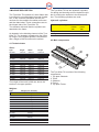
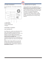
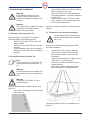
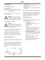
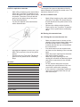
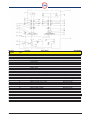
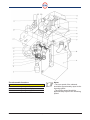
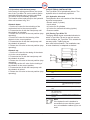
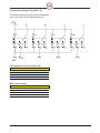
1
Tyre-Killer TK
User manual, Version 1.4
® Pevac 04-2002
Nothing in this manual may be reproduced and/or published by means of print, photocopy,
microfilm or any other means whatsoever, without the prior permission of Pevac B.V.
This also applies for the associated illustrations.
en - 2
Tyre-Killer TK
04-2002
Pevac Tyre-Killer TK
The Pevac Tyre-Killer TK is a special dynamic
anti-terrorism blockade which is provided with
specially hardened teeth. The Tyre-Killer TK is
a high quality product for the highest degree
of protection. In case of a collision, the special
teeth penetrate and totally destroy both the
tyres and the wheel rims of the unauthorised
vehicle. The teeth can rise out of the road
surface or sink back into it in only a few
seconds.
Declaration of agreement
The Tyre-Killer TK is accompanied by a manufacturer’s declaration. With this, the product
complies with the New Approach guidelines,
which guarantees optimal safety. However, it’s
forbidden for people to come close tot the TyreKiller TK, when raised or when operated.
The manufacturer is never responsible for
damage or personal injurie.
The Tyre-Killer TK is hydraulically driven. The
hydraulic drive is electrically operated. There
are a great number of possibilities for operation,
from simple, manual operation to advanced
entry control systems.
04-2002
Tyre-Killer TK
en - 3
TABLE OF CONTENTS
1
USE OF THE INSTALLATION
MANUAL
1.1
1.2
2
Related documentation
7
Use according to destination 7
15
8.1
8.2
8.2.1
15
15
15
8.2.2
2.1
2.2
8
8
8.3
8.4
8.5
8.6
8.6.1
Safety and health risks
Safety precautions of the
Tyre-Killer TK
Recommended environmental safety provisions
Safety precautions and
maintenance
GUARANTEE
3.1
Liability
8
9
4.1
4.2
4.3
4.4
4.4.1
4.4.2
11
11
12
12
12
12
OPERATION AND USE
6
PERIODIC INSPECTION BY
OWN PERSONAL
7
STORAGE AND TRANSPORT
7.1
7.2
7.3
8.7
8.8
8.9
8.9.1
10
11
Technical data
Main components
Product identification
Principles of operation
Tyre-Killer TK
Mechanical Lock (option)
8.6.2
10
MACHINE DESCRIPTION
5
en - 4
INSTALLATION
8
2.4
4
8
SAFETY
2.3
3
7
8.9.2
8.10
9
13
13
14
Storage of the Tyre-Killer TK 14
Transport of the Tyre14
Killer TK
Transport of the concrete
14
foundation
Tyre-Killer TK
15
15
16
16
16
16
16
17
17
17
17
17
17
HYDRAULIC SYSTEM
18
9.1
9.2
18
18
9.3
10
Installation preparation
Installation conditions
Hydraulic drive unit in
installation cabinet
Hydraulic drive unit in a
separate room
Materials to be used
Pit in asphalt or concrete
Pit in cobbled road
Placing the concrete base
Fixing the concrete base on
site
Fixing the pre-fabricated
concrete base
Sealing the pit
Placing the Tyre-Killer TK
Fitting the jacket sleeves
For use of an installation
cabinet
For use in a mechanical
room
Installation of hoses and
cables
Hydraulic drive unit
Hydraulic drive unit, type
HC-ML
Operation with the hand
pump
21
ELECTRICAL INSTALLATION
21
10.1
10.2
10.3
21
21
22
10.4
Hydraulic drive unit
Placing the Tyre-Killer TK
Cable diagram TyreKiller TK
Electrical diagram TyreKiller TK
23
04-2002
11
CONNECTION OF THE TYREKILLER TK
24
11.1
11.2
24
24
11.3
11.3.1
11.3.2
11.3.3
11.3.4
12
13
14
04-2002
Electrical connections
Placing and connecting
the controller box
Hydraulic connections
Bleeding air from the
hydraulic hoses of the lift
Bleeding air from the
hydraulic hoses of the
Mechanical Lock
Hydraulic connections
Tyre-Killer TK
Hydraulic connections
Mechanical Lock (option)
24
24
24
25
25
COMMISSIONING
26
12.1
12.2
12.3
12.4
12.5
Function for switches
Preventing access
Permitting access
Checking the operation
Final assembly
26
27
27
27
27
GENERAL INSPECTION AND
MAINTENANCE
28
13.1
28
Service intervals
THE TYRE-KILLER TK AND THE
ENVIRONMENT
28
14.1
28
End of life span
Tyre-Killer TK
en - 5
This page is empty
en - 6
Tyre-Killer TK
04-2002
1 USE OF THE INSTALLATION MANUAL
This manual is intended for persons who are
responsible for installing, operating and
maintaining the Tyre-Killer TK. This manual describes how the Tyre-Killer TK can be safely
installed, used and maintained.
Read the manual completely before installing or
using the Tyre-Killer TK.
Keep this manual in the control room.
In this manual the following pictograms and
symbols are used:
Warning
Danger of injury to operator or
bystanders, or danger of major
damage to the Tyre-Killer TK or to
other objects. Follow the instructions carefully.
Danger
Life threatening danger or danger
of serious injury. Follow the instructions carefully.
Note
Tip to make work easier.
Environment
Remark regarding the environmental impact of the Tyre-Killer TK in
operation and of the Tyre-Killer TK
should be disposed of.
• Action
Actions to be taken.
04-2002
This manual has been drafted with the utmost
care. Pevac B.V. is not liable for damage that
occurs as a result of any inaccuracies in this
manual. We request that you inform us, as a
matter of urgency, of any inaccuracies you may
find.
1.1 Related documentation
As well as this manual for the Tyre-Killer TK,
there are also the following documents:
- Maintenance book Tyre-Killer TK.
- Log card.
- Hydraulic drawings.
- Controller drawings.
1.2 Use according to destination
The Tyre-Killer TK may NOT be used on a
public road. In terrain’s where the Tyre-Killer TK
has been installed, a maximum speed of 30
km/hour must be observed.
The Tyre-Killer TK may not be used for moped
riders, cyclists, motorcycle riders and
pedestrians.
The Tyre-Killer TK can be used in the following
situations:
Security of amongst others:
- Military bases;
- Banks;
- Financial institutions;
- Embassies;
- High security industrial area’s.
Any other or extended use does not comply with
the intended use. Use and install the
Tyre-Killer TK only when it is in technically perfect condition.
Tyre-Killer TK
en - 7
2 SAFETY
In this chapter, the safety aspects of the Pevac
Tyre-Killer TK are discussed.
Read this chapter thoroughly before use of the
Tyre-Killer TK.
2.3 Recommended environmental safety provisions
2.1 Safety and health risk
The Tyre-Killer TK has been safely constructed.
At each installation in a certain environment,
new risks can occur that can be different for
each installation. The customer must carefully
assess beforehand what risks can occur after
the installation. In general the following risks
can be distinguished:
Collision with the Tyre-Killer TK due to
bad visibility;
Collision due to excessive speed;
Possible injury to moped riders, cyclists,
motorcycle riders and pedestrians
because they are too close to the TyreKiller TK.
During the design of the Tyre-Killer TK, safety
precautions were taken to reduce these risks
as much as possible. By taking account of the
above risks and by following the safety regulations, these risks are limited even more.
2.2 Safety precautions of the Tyre-Killer TK
To make the use of the Tyre-Killer TK as safe
as possible, the following safety measures have
been taken:
A clear colour choice ensures good visi
bility of the Tyre-Killer TK;
Accumulation of dirt can reduce the visi
bility of the Tyre-Killer TK. The accumu
lation of dirt will be limited due to the
smooth surface of the Tyre-Killer TK;
To prevent slipperiness of the Tyre-Killer
TK in the sunken condition, as much as
possible, the top plate is fitted with an
anti-slip surface.
en - 8
Tyre-Killer TK
Warning
Environmental measures must be
taken for the safe use of the TyreKiller TK. The necessary measures
will be different for each situation. In
general the following measures
will contribute to decreasing risks for
road users.
Danger
The environment must be adapted
in such a way that a high speed
(higher than 30 km/hour) is hard to
reach, for example by bumps in the
road surface, an S-curve (with unobstructed view) in the road and maximum speed signs.
Danger
In order to ensure the safety of
moped riders, cyclists, motorcycle
riders and pedestrians, they must
not be permitted in the vicinity of
the Tyre-Killer TK. Establishing a
danger zone with the help of traffic
signs, text signs, pictograms, road
markings and the physical separation of traffic flows can facilitate this.
Warning
Traffic lights, warning boards, and
lighting should be placed in the vicinity to insure good visibility of the
Tyre-Killer TK.
Danger
If a traffic light is to be utilised, the
green light may only be given if the
obstacle is in the lowest position:
this indicates that the passage is
completely unobstructed. The traffic
light must change to red several
seconds before the Tyre-Killer TK is
raised in order to give road users
sufficient time to stop. The traffic
light must remain red while the TyreKiller TK is moving and while it is in
the highest position.
04-2002
Warning
It is forbidden to stop or to park
above the Tyre-Killer TK. Traffic
signs can also indicate this.
2.4 Safety precautions and maintenance
Note
It is advisable to make recordings
with a security camera in the vicinity
of the Tyre-Killer TK.
This has the advantage of providing
a record of a possible collision and
allowing a determination of the possible cause. Furthermore, sabotage
can be witnessed and recorded.
•
•
•
•
•
Warning
The obstacle must not rise if vehicles are above the Tyre-Killer TK. To
this end, detection systems such as
detection loops in the road surface,
photocells, or cameras can be used.
Check the Tyre-Killer TK on every first
working day of the week for proper func
tioning.
Check the visibility of the Tyre-Killer TK
every first working day. Remove dirt and
replace the striping if it is damaged.
Carry out maintenance in accordance
with the specifications in the maintenance and repair logbook.
During installation and maintenance
work, the drive must be disengaged.
The Tyre-Killer TK can only be operated
by personnel who are adequately
trained and familiar with the operation.
Warning
Fault detection can be used. In the
event of a fault, the traffic light must
change to red and remain red. Additionally, in that case, a signal must
be sent to the central control room.
04-2002
Tyre-Killer TK
en - 9
3 GUARANTEE
-
Guarantee is given according to the conditions
stated in the “Conditions of the Metal Union”.
Pevac BV, however, gives a guarantee for a
period of 24 months instead of 6 months, as
stated in 14.1 of the conditions of the metal
union. A copy of these conditions can be
obtained from Pevac BV.
The Tyre-Killer TK has been manufactured with
the utmost care. Therefore, Pevac BV gives the
initial user a guarantee for 24 months, taken
from the invoice date.
The guarantee implies that Pevac BV makes
replacement parts available, free of charge,
for all parts that show any shortcomings, within
the term mentioned, due to imperfections of the
material or manufacture.
Excluded from guarantee are all parts that
should be replaced according to the maintenance schedule.
-
The repair or replacement of parts during the
period of guarantee does not result in the
extension of this term. Replaced parts become
property of Pevac BV.
The guarantee concerns the replacement of
defective parts, exclusive of installation,
at the discretion of Pevac BV.
Pevac BV explicitly rejects all further claims for
compensation of damage, of any nature. The
guarantee does not apply for faults that have
occurred due to injudicious, incorrect or careless handling, incorrect use, incorrect connection or connection by unqualified parties.
The guarantee expires if:
Unauthorised parties have carried out
repairs or maintenance to the installa
tion;
The installation was not used in accordance with the normal intended use or
was used under abnormal circumstan
ces;
en - 10
-
It cannot be shown that the installation
was inspected by a qualified installer or
service organisation in accordance with
the maintenance schedule;
The complaint is not immediately repor
ted to a qualified installer or service
organisation;
Repairs are carried out without the prior
permission of Pevac BV;
Parts are replaced without prior permission from Pevac BV;
Original parts are not used during
repair;
The damage was caused by use other
than mentioned in § 1.2 “Use according
to intended purpose”;
Claims do not take place within eight
days after the complaint was discovered
or reasonably should have been disco
vered.
If necessary, Pevac BV can require that the
parts are shipped postage-paid to Pevac BV.
Postage-paid return is made if the repair was
carried out under guarantee.
Excluded from guarantee is all damage that
has occurred to the Tyre-Killer TK by persons,
vehicles, or adjacent moveable or immovable
property.
3.1 Liability
Pevac BV accepts no liability for damage or
physical injury that occurs due to:
Not following the instructions in this
manual;
Carelessness during the use, main
tenance, repositioning, installing, dis
mantling or repair of the Tyre-Killer TK;
Use that is not in compliance with the
intended purpose.
Tyre-Killer TK
04-2002
4 MACHINE DESCRIPTION
The Tyre-Killer TK consists of a steel frame that
is mounted in a pre-fabricated concrete foundation. In the concrete foundation are the connections for the conduits for cables and hoses
and the drain tubes. These connections are on
the hinged side of the Tyre-Killer TK.
The obstacle with teeth and the cylinders are
attached to the frame.
An obstacle is the blocking element of the TyreKiller TK. The obstacle is attached to the frame
by hinges. In the highest position, the obstacle
has a height of 280 mm above the surface.
The Tyre-Killer TK has two hydraulic cylinders
for raising and lowering and one hydraulic cylinder for locking the obstacle in the raised position. The following cylinders are used.
Hydraulic cylinders:
Name
Cylinder type
Volume
Volume
bottom
piston
side
side
Lifting
30/20 - 250 mm
354 cc
197 cc
Locking
25/15 - 40 mm
19.6 cc
15.1 cc
4.2 Main components
4.1 Technical data
Sizes:
Type
Height
Width
Length
TK 2000
450 mm
830 mm
2100 mm
TK 2500
450 mm
830 mm
2600 mm
TK 3000
450 mm
830 mm
3100 mm
TK 3500
450 mm
830 mm
3600 mm
TK 4000
450 mm
830 mm
4100 mm
TK 4500
450 mm
830 mm
4600 mm
TK 5000
450 mm
830 mm
5100 mm
TK 5500
450 mm
830 mm
5600 mm
TK 6000
450 mm
830 mm
6100 mm
TK 6500
450 mm
830 mm
6600 mm
TK 7000
450 mm
830 mm
7100 mm
TK 7500
450 mm
830 mm
7600 mm
TK 8000
450 mm
830 mm
8100 mm
The height of the teeth is 280 mm above the
surface in its upper position.
The Tyre-Killer TK consists of the following
components:
1. Top plate Obstacle.
2. Teeth.
3. Obstacle.
4. Frame.
5. Top plate Frame.
Weights:
Type
Weight (incl. obstacle)
TK 2000
575 kg
TK 2500
700 kg
TK 3000
825 kg
TK 3500
950 kg
TK 4000
1075 kg
TK 4500
1200 kg
TK 5000
1325 kg
TK 5500
1450 kg
TK 6000
1575 kg
TK 6500
1750 kg
TK 7000
1875 kg
TK 7500
2000 kg
TK 8000
2150 kg
04-2002
Tyre-Killer TK
en - 11
4.3 Product identification
4.4.2 Mechanical Lock (option)
The type plate (fig. 4.3) contains the following
data:
The Tyre-Killer TK can be equipped with a
Mechanical Lock (ML). This ML is a mechanical
lock that locks the obstacle on the Tyre-Killer
TK in the highest position. In this way, the TyreKiller TK cannot be lowered even if the hydraulic pressure is completely diminished,
in the case of sabotage for instance. The
mechanical lock is operated with a hydraulic
cylinder. The position of the mechanical lock
is detected through the use of two proximity
switches.
1. Type number
2. Serial number
3. Year of construction
4. Weight
4.4 Principles of operation
4.4.1 Tyre-Killer TK
According to the “quickly up, quickly down” principle, a steel obstacle can be moved that
provides a dynamic blockade of the terrain. This
obstacle is moved upward with hydraulic
cylinders to block a passage and moved downward to make the passage free.
The teeth of the Tyre-Killer TK are pointing
towards the attack side. There are two proximity
switches mounted in the frame of the Tyre-Killer
TK.
With the help of these switches, the two end
positions of the obstacle can be determined
or a fault detected. The Tyre-Killer TK can be,
depending on the controller used, manually or
automatically operated.
en - 12
Tyre-Killer TK
04-2002
5 OPERATION AND USE
Depending on the manner in which the TyreKiller TK is installed, a separate user manual
for operation may be applicable. See the user
manual included with the controller system.
04-2002
6 PERIODIC INSPECTION BY OWN PERSONAL
To guarantee the safety and the proper functioning of the Tyre-Killer TK maintenance is necessary.
Every week the following actions must be taken:
•
Check the Tyre-Killer TK for correct
functioning.
•
Check the visibility of the Tyre-Killer TK.
•
Remove dirt from the Tyre-Killer TK.
•
Check that no water remains in the TyreKiller TK.
Tyre-Killer TK
en - 13
7 STORAGE AND TRANSPORT
-
Warning
Ensure that for lifting work, the
strength of the hoisting belts or
chains can handle the weight to be
hoisted.
Warning
Ensure that the Tyre-Killer TK hangs
completely horizontally and in
balance during hoisting.
7.1 Storage of the Tyre-Killer TK
When storing the Tyre-Killer TK, attention
should be paid to the following points:
Place the Tyre-Killer TK on a flat and
stable surface.
Protect the Tyre-Killer TK from dirt and
moisture.
Prevent damage to the zinc coating by
placing the Tyre-Killer TK on a wooden
surface.
7.2 Transport of the Tyre-Killer TK
Note
For the weight of the Tyre-Killer TK,
see the technical specifications, §
4.1.
-
Hoist the Tyre-Killer TK with four hoisting
belts or chains on the truck.
Place the Tyre-Killer TK horizontally on
the loading platform, so that the obstacle
is on the top.
Fasten the Tyre-Killer TK firmly on the
truck, so that it cannot slide in any direc
tion during transportation.
The same directions apply for unloading as for
loading.
7.3 Transport of the concrete foundation
For the weight of the concrete foundation, see the technical specifications, § 4.1.
Sequence of working during transport of the
concrete foundation:
-
-
Warning
Prevent damage to the powder coating and the zinc layer during transport.
Screw the 4 crane hooks or hoisting
loops into the screw sleeves that are
poured in the bottom of the concrete
foundation.
Install the hoisting belts or chains on the
crane hooks or hoisting loops.
Hoist the concrete foundation onto the
loading platform
Make sure that the foundation is secu
rely attached to the loading platform.
Warning
Position the Tyre-Killer TK on a
wooden surface.
Order of working when transporting the TyreKiller TK:
Screw the 4 hoisting eyes into the inten
ded locations
The same guidelines apply to unloading as to
loading.
en - 14
Tyre-Killer TK
04-2002
8 INSTALLATION
8.1 Installation preparation
Note
The hydraulic drive unit must be
installed within a radius of 15 m from
the Tyre-Killer TK.
For successful installation you should prepare
yourself as follows:
Danger
During the installation (and also
during other work on the Tyre-Killer
TK), the power supply of the installation must always be switched off.
8.2 Installation conditions
Warning
The Tyre-Killer TK can only be installed, inspected, maintained and/or
repaired by personnel who are qualified by Pevac BV.
At the place of installation, the necessary control cables and hoses must be present.
Depending on the road surface in which the
Tyre-Killer TK must be installed, it will be
necessary, in accordance with the installation,
to make a pit and a trench in the road surface
in:
- Asphalt hardening (see § 8.4), or
- Cobbled road (see § 8.5).
8.2.1 Hydraulic drive unit in installation cabinet
1. Tyre-Killer TK
2. Installation cabinet with controller and
hydraulic drive
3. Jacket sleeve for feed-through of the cables
and hoses
8.2.2 Hydraulic drive unit in a separate room
If the hydraulic drive unit is to be installed in a
separate mechanical room, together with the
controller, a jacket sleeve for the drive unit and
the controller must be laid from this area
to the Tyre-Killer TK.
8.3 Materials to be used
For positioning the Tyre-Killer TK, the following
equipment / tools are necessary:
Crane truck.
Hoisting belts or chains.
Diamond saw (only for asphalt or con
crete hardening).
Gravel.
Concrete.
PVC jacket sleeve with connectors
(ø 100 mm or ø 125 mm) for the hydrau
lic hoses and the electrical cable.
Pull cord, to pull the cables and hoses
through the jacket sleeve.
PVC drain tube with sleeves (ø 100 mm
or ø 125 mm) for the drainage of rainwater (if connection to the sewer is possible).
Electrical connection (in the control
room) with main switch.
PUR foam (only to be used if the
hydraulic drive unit is to be placed in a
separate mechanical room).
The hydraulic drive unit can be placed, together
with the controls, in an installation cabinet. A
jacket sleeve for the cables and hoses must
be laid from the installation cabinet to the TyreKiller TK.
04-2002
Tyre-Killer TK
en - 15
8.4 Pit in asphalt or concrete
•
•
Mark off the location on the road surface
where the Tyre-Killer TK should be posi
tioned and where the jacket sleeve must
be placed. The sizes of the pit and the
groove for the jacket sleeve are given
in the following tables.
Cut into the asphalt a few centimetres
with a diamond saw.
The length of the groove depends on the distance between the pit and the control room. The
maximum distance is 15 m.
8.5 Pit in cobbled road
•
•
•
Mark off the location on the road surface
where the Tyre-Killer TK should be posi
tioned and where the jacket sleeve must
be placed.
Remove the cobbles at that location.
Dig the pit for the Tyre-Killer TK and the
groove for the jacket sleeve sufficiently
deep.
8.6 Placing the concrete base
8.6.1 Fixing the concrete base on site
•
•
•
Dig away the asphalt in front of the TyreKiller TK as well as in front of the jacket
sleeve.
Dig the pit for the Tyre-Killer TK and the
groove for the jacket sleeve sufficiently
deep.
Pit sizes:
Type
Depth
Width
Length
TK 2000
650 - 700 mm
1500 mm
2800 mm
TK 2500
650 - 700 mm
1500 mm
3300 mm
TK 3000
650 - 700 mm
1500 mm
3800 mm
TK 3500
650 - 700 mm
1500 mm
4300 mm
TK 4000
650 - 700 mm
1500 mm
4800 mm
TK 4500
650 - 700 mm
1500 mm
5300 mm
TK 5000
650 - 700 mm
1500 mm
5800 mm
TK 5500
650 - 700 mm
1500 mm
6300 mm
TK 6000
650 - 700 mm
1500 mm
6800 mm
TK 6500
650 - 700 mm
1500 mm
7300 mm
TK 7000
650 - 700 mm
1500 mm
7800 mm
TK 7500
650 - 700 mm
1500 mm
8300 mm
TK 8000
650 - 700 mm
1500 mm
8800 mm
•
•
•
•
•
Make a wooden base as shown on the
drawing of the concrete base. Make sure
that the wooden base is completely
levelled and that the top is levelled with
the road surface.
Put reinforcement in the wooden base
as shown on the drawing of the concrete
base.
Make the proper openings for the bolds
and put the inserts in place.
Make the proper openings for connecting the conduits and drainage pipes,
and put the connectors for the conduit
in place.
Fill the wooden base with concrete
according the specifications of the con
crete base construction company.
If the concrete is completely hardened,
remove the wooden shelf from the pit
and clean the pit.
Grove sizes:
Depth
Width
700 - 800 mm
250 mm
en - 16
Tyre-Killer TK
04-2002
8.6.2 Fixing a pre-fabricated concrete base
Warning
Ensure that for lifting work, the
strength of the hoisting belts or
chains can handle the weight to be
hoisted.
•
•
Flatten out the bottom of the pit.
Position the concrete base in the pit so
that:
- It is completely levelled.
- The top rim is levelled with the road
surface.
8.9 Fitting the jacket sleeves
8.9.1 For use of an installation cabinet
•
•
•
•
8.7 Sealing the pit
•
•
-
Fill up the space surrounding the con
crete base with sand and seal it pro
perly.
Fill up the remaining space with glassfibre reinforced concrete, in accordance
with the concrete supplier’s specificati
ons.
In the case of a cobblestone road, cover
the opening above the concrete
with previously removed cobblestones.
Note
Put the cobblestones in the concrete. Do not use sand under the
cobblestones.
8.9.2 For use in a mechanical room
•
•
•
•
8.8 Placing the Tyre-Killer TK
•
•
Position the Tyre-Killer TK, inside the
concrete base on the hoisting gin, in the
pit so that:
- It is completely level.
- The top rim is level with the road
surface.
Remove the hoisting eyes from the TyreKiller TK.
Create a feed-through from the mecha
nical room with a diameter of 125 mm,
at an angle of 45°, so that this ends up
on the outside, below the surface.
Put the supplied jacket sleeve in the
groove, pass one end in the connector
that’s in the centre of the concrete base
and the other end in the wall feedthrough, to a position about 10 cm under
the floor surface.
Feed the pull cord through the jacket
sleeve.
Fit the drain tube for rain water drainage
and connect it to the sewer at the other
end (if appropriate).
8.10 Installation of hoses and cables
•
•
Warning
The attack side (this is the teeth side
of the Tyre-Killer TK) must be positioned on the correct side.
Warning
Do not use 90º bends in the corners
of the jacket sleeve for the feedthrough of the hydraulic hoses.
04-2002
Put the jacket sleeve in the groove and
connect one end to the connector that’s
inserted in the centre of the concrete
base.
Connect the other end of the conduit in
the wall feed-through in the base of the
installation cabinet.
Feed the pull cord through the jacket
sleeve.
Fit the drain tube for rain water drainage
and connect it to the sewer at the other
end (if appropriate).
Tyre-Killer TK
Remove the cover plates (deck plates)
of the Tyre-Killer TK.
Pull the hydraulic hoses and the electri
cal cable through the jacket sleeve. Use
the pull cord in the jacket sleeve for this
purpose.
- Be certain that the hydraulic hoses in
the Tyre-Killer TK are sufficiently long.
- Be certain that the cable in the TyreKiller is sufficiently long.
Note
Be certain that there are no kinks in
the hydraulic hoses or the cable.
en - 17
9 HYDRAULIC SYSTEM
9.1 Hydraulic drive unit
A hydraulic drive unit is necessary to drive the
Tyre-Killer TK. For good, reliable operation of
the Tyre-Killer TK, it is necessary to use a
hydraulic unit that meets the following minimum
specifications:
Minimum
working
pressure
Maximum
working
pressure
Pump
capacity
Tank
capacity
70 bar
110 bar
7.8 cc
4 litre
For operation of the Tyre-Killer TK, the unit must
be equipped with electrically operated hydraulic
valves for:
1.
Raising and lowering the obstacle;
2.
Extension and retraction of the mechani
cal lock.
For operation of the hydraulic drive unit see the
manufacturer’s directions.
Hydraulic unit HC-078 ML:
Pump
capacity
Voltage
Motor
power
Rise and
fall time
7.8 cc/
380 V
2.2 kW
1.9 sec
revolution
(3 phase)
4/3 valve (back and forth):
Flow rate
Voltage
Power
Maximum
working
pressure
50 l/min
230 VAC
28 W
250 bar
9.2 Hydraulic drive unit, type HC-ML
The diagram on the next page shows the
hydraulic system of the unit HC-ML. In the drawing, component locations are indicated with
labels:
1. In the Tyre-Killer TK.
2. In the hydraulic drive unit.
Some of the components shown in the hydraulic
diagram for the HC-ML unit are mounted on the
hydraulic drive unit. The following table shows
which components are located on the hydraulic
drive unit.
Obstacle down:
If the controller gives the command ‘obstacle
down’, the gear pump (H) begins to turn,
through which the hydraulic oil becomes pressurized. As result, the 4/3 valve (T) of the
mechanical lock is operated, through which the
obstacle is unlocked. If the lock is moved, the
sensor detects this condition. Thereafter, the 4/3
valve for the mechanical lock is deactivated.
Then the 4/3 valve for the lift cylinders is operated, through which the top side (or rod side) of
the cylinders (Q) comes under pressure and the
cylinders are driven downward. As result, the
return valve is brought under pressure, through
which it is opened, so that the oil under the
cylinders can flow back to the reservoir. Once
the obstacle has moved completely
downward, a sensor detects this condition and
the 4/3 valve for the lift cylinders switches the
gear pump off. The 4/3 valve for the lift cylinders
returns to the rest position.
Obstacle up:
If the controller gives the command ‘obstacle
up’, the gear pump (H) begins to turn, through
which the hydraulic oil comes under pressure.
As result, the 4/3 valve (K) is operated, through
which the under side (or bottom side) of the
cylinders (Q) comes under pressure, and the
obstacle is raised.
The oil on the top side of the cylinders flows
freely back to the reservoir.
Once the obstacle has moved upward, a sensor
detects this condition and switches the 4/3 valve
off. Thereafter, the 4/3 valve for the mechanical
lock is activated, through which the corresponding cylinder (Y) comes under pressure and the
lock extends.
A sensor detects this condition and switches the
gear pump off. The 4/3 valve for the
mechanical lock is deactivated and returns to
the rest position. The hydraulic return valve
(M) prevents the obstacle from sinking downward through its own weight or the leakage of
oil.
With the hydraulic drive unit, type HC-ML, the
obstacle can be lowered and raised, and the
obstacle is locked in the highest position with
the mechanical lock.
en - 18
Tyre-Killer TK
04-2002
Position
Diagram
A
B
C
D
E
F
G
H
I
J
K
L
M
N
O
P
Q
R
S
T
U
V
W
X
Y
Valve spool
K1
K2
S1
S2
04-2002
Unit
A
B
C
D
E
G
K
L
M
N
O
P
R
S
T
U
V
W
X
-
Position
Description
Oil tank
Tank level indicator with level switch
Fill cap with filter
Manometer with manometer valve
Pressure switch
Suction filter
Electric motor (3 phase)
Gear pump
Over-pressure valve (set at 100 bar)
Return valve
Manual control for 4/3 valve
4/3 valve (electrically operated / spring return)
Return valve (hydraulically operated)
Throttle needle
Quick coupler: male
Quick coupler: female
Hydraulic cylinder
Hand pump
Manual control for 4/3 valve
4/3 valve (electrically operated / spring return)
Throttle needle
Throttle needle
Quick coupler: female
Quick coupler: male
Hydraulic cylinder
Associatedwith
Hydraulic pump drive
Lift cylinders
Lift cylinders
Lift cylinders
Lift cylinders
Lift cylinders
Lift cylinders
Hoisting obstacle
Mechanical lock
Mechanical lock
Mechanical lock
Mechanical lock
Mechanical lock
Mechanical lock
Mechanical lock
Function
Obstacle up
Obstacle down
Mechanical lock Unlocked
Mechanical lock Locked
Tyre-Killer TK
en - 19
Throttle needle functions:
Position
Description
N
Regulating lowering speed of obstacle
U
Regulating unlocking speed
V
Regulating locking speed
en - 20
Tyre-Killer TK
Notes:
• The rise speed of the obstacle
should be approximately equal to the
lowering speed.
• The locking speed should be
approximately equal to the unlocking
speed.
04-2002
9.3 Operation with the hand pump:
In the event of mains power failure, the operation of the Tyre-Killer TK can be entirely performed with the hand pump, in which case both
4/3 valves must be manually operated.
The location of the hand pump on the hydraulic
drive unit is shown in fig. 9.6.
Obstacle down:
1. Set the 4/3 valve for the unlocking of the
mechanical lock in the correct position.
2. Pressurise the oil with the hand pump until
the obstacle is unlocked.
3. Return the 4/3 valve to the rest position (stop
operating).
4. Set the 4/3 valve for the lowering of the
obstacle in the correct position.
5. Pressurise the oil with the hand pump until
the obstacle is lowered.
6. Return the 4/3 valve to the rest position (stop
operating).
Obstacle up:
1. Set the 4/3 valve for the raising of the obstacle in the correct position.
2. Pressurise the oil with the hand pump until
the obstacle is raised.
3. Return the 4/3 valve to the rest position (stop
operating).
4. Manually set the 4/3 valve for the locking of
the obstacle in the correct position.
5. Pressurise the oil with the hand pump until
the obstacle is locked.
6. Return the 4/3 valve to the rest position (stop
operating).
10 ELECTRICAL INSTALLATION
The Tyre-Killer TK is hydraulically driven. The
hydraulic drive is electrically operated.
10.1 Hydraulic drive unit
The hydraulic drive unit consists of the following
electrical components:
• Electric motor (3 phase)
• Level switch
• 4/3 valve for lift cylinders
• 4/3 valve for mechanical locking (option)
• Pressure switch
10.2 Placing Tyre-Killer TK
The figure below shows a standard situation in
which a Tyre-Killer TK can be put into service.
In this situation, the Tyre-Killer TK is suitable for
two-way traffic. Traffic lights are
also used in this situation. The installation can,
in most situations, be adapted as desired.
Pos.
Description
Function
A.
Open detection
loop.
Automatic ride-out.
B.
Driveway.
C.
Safety detection
loop.
D.
Tyre-Killer TK
E.
Traffic light
Warning if the Tyre-Killer TK is
raised: Ride-through is not possi
ble!
F.
Safety detection
loop.
Automatic closing of the passage.
G.
Installation cabinet Control of the Tyre-Killer TK.
with controller and
hydraulic drive unit.
H.
Push-button
console.
Automatic closing of the passage.
Operation of the Tyre-Killer TK.
Note:
If the hydraulic unit is installed in
a mechanical room with the controllers, an installation cabinet (G) is not
used.
04-2002
Tyre-Killer TK
en - 21
10.3 Cable diagram Tyre-Killer TK
The figure shows the standard cabling diagram
for the Tyre-Killer TK installation. The table
below shows the cables that are used.
Cables and hoses for Tyre-Killer TK controller:
Pos.
Cable type
From
To
1.
Power cable – armoured,
with tinned copper ground wire,
5 conductors, 2.5 mm2 (12 AWG)
Power supply
Controller
2.
Signal cable – armoured and
shielded, 5 twisted pairs,
0.8 mm2 (18 AWG)
Controller
3.
Hydraulic hose 3/8”
Hydraulic unit
Tyre-Killer TK
Obstacle up
Hydraulic hose 3/8”
Hydraulic unit
Tyre-Killer TK
Obstacle down
Hydraulic hose 3/8”
Hydraulic unit
Tyre-Killer TK
Obstacle: unlock
Hydraulic hose 3/8”
Hydraulic unit
Tyre-Killer TK
Obstacle: lock
Tyre-Killer TK
Approach switches (4x)
Signal cable, armoured and
shielded, 3 twisted pairs,
0.8 mm2 (18 AWG)
Function
3 phase = neutral + ground
Push-button cabinet
Controller
Operation
4.
Power cable – armoured, with
tinned copper ground wire,
3 conductors, 1.5 mm2 (14 AWG)
Controller
Traffic light
Red / green
5.
Power cable – armoured, with
tinned copper ground wire,
3 conductors, 1.5 mm2 (14 AWG)
Controller
Traffic light
Red / green
6.
Signal cable – armoured and
shielded, 1 twisted pair, 0.8 mm2
(18 AWG)
Controller
Detection loop
Closedsafetydetectionloop
7.
Signal cable – armoured and
shielded, 1 twisted pair, 0.8 mm2
(18 AWG)
Controller
Detection loop
Closedsafetydetectionloop
8.
Signal cable – armoured and
shielded, 1 twisted pair, 0.8 mm2
(18 AWG)
Controller
Detection loop
Auto exit detection loop
en - 22
Tyre-Killer TK
04-2002
10.4 Electrical diagram Tyre-Killer TK
The drawing below shows the electrical diagram
of the Tyre-Killer TK with Mechanical Lock.
Limit switches in the Tyre-Killer TK:
Code
Function
A
Limit switch Down.
B
Limit switch Up.
C
Limit switch Unlocked.
D
Limit switch Locked.
Wire colour coding:
Code
Wire colour
BU
Blue
BN
Brown
BK
Black
WH
White
04-2002
Tyre-Killer TK
en - 23
11 CONNECTION OF THE TYRE-KILLER TK
This chapter describes how the Tyre-Killer TK
should be connected electrically and hydraulically.
11.1 Electrical connections
•
Connect the controller cable to connection strip ‘X1’ of the Tyre-Killer TK accor
ding to the table below. Thereafter,
check the connections carefully.
Note
For air bleeding, see also the user
manual for the hydraulic drive unit.
•
Function
X1.1
Feed voltage +24 VDC
X1.2
Ground
X1.3
Obstacle down (Contact proximity
switch Down)
X1.7
Obstacleup(Contactproximityswitch
Up)
X1.11
ObstacleUnlocked(Contactproximity
switch Unlocked)
X1.15
ObstacleLocked(Contactproximity
switch Locked)
11.2 Placing and connecting the controller
box
The placement and connection of the controllers and the push button panel depends on the
chosen installation and the control. The installation thereof is given in the accompanying documentation.
11.3 Hydraulic connections
Danger
• During connection of the hydraulic
hoses, the hoses MUST NOT be
under pressure.
• The electrical mains power must be
switched off.
Warning
When working with hydraulic
systems be extremely clean: sand
and other contaminants can lead to
failures and excessive wear of the
system.
en - 24
11.3.1 Bleeding air from the hydraulic hoses
of the lift
•
Electrical connections:
Terminal
Warning
Ensure that the oil tank is always full.
Connect the hydraulic hoses of the lift (in
the Tyre-Killer TK) to one another.
Connect the outlets of the hydraulic drive
unit together.
Careful
The hydraulic hoses supplied by
Pevac are already filled with hydraulic oil. For this reason fasten the
hoses well, so that no oil can escape
from the hoses, which would cause
difficulty in the bleeding of air.
•
•
•
•
Open the lift valve.
Let the pump turn for approximately 10
minutes so that all the air is forced out
of the hoses.
Stop the pump and set the power off.
Loosen the hoses of the Tyre-Killer TK
from one another.
- In order to detach the hoses, the ring of
the quick-coupling must be retracted.
11.3.2 Bleeding air from the hydraulic hoses
of the mechanical lock
Perform this procedure now for the hydraulic
hoses of the mechanical lock:
•
Attach the ends of the hoses (in the
Tyre-Killer TK) together.
•
Connect the outlets of the hydraulic drive
unit together.
•
Open the valve for the mechanical lock.
•
Let the pump turn for approximately 10
minutes so that all the air is forced out
of the hoses.
•
Stop the pump and set the power off.
•
Loosen the hoses of the Tyre-Killer TK
from one another.
- In order to detach the hoses, the ring of
the quick-coupling must be retracted.
Tyre-Killer TK
04-2002
11.3.3 Hydraulic connections Tyre-Killer TK
If the hydraulic hoses are free of air, the TyreKiller TK can be connected as follows:
•
Connect the hoses to the quickconnec
tors on the T-pieces in the Tyre-Killer TK.
•
Loosen the swivel couplings on the top
of the cylinders (as a rule, it is sufficient
to loosen the couplings two turns).
Careful
The screw threads in the hydraulic
cylinders must not be damaged!
•
•
•
•
Let the obstacle rise to remove all of the
air from the cylinders. By preference,
use the hand pump (if present) to do
this.
Re-tighten the swivel couplings on the
top of the cylinders.
Allow the obstacle to fall.
Check the oil level once again.
Connection of the mechanical lock in the
Tyre-Killer TK:
Pos.
Connection type
Function
A.
Male
Lock
B.
Female
Unlock
Connections for the Tyre-Killer TK:
Pos.
Connection type
A.
Male
Obstacle up
Function
B.
Female
Obstacle down
11.3.4 Hydraulic connections mechanical
lock (option)
If the Tyre-Killer TK is connected, see § 11.2.2,
the mechanical lock can be connected as follows:
•
Connect the hoses to the quick-connec
tors mounted in the middle section of the
Tyre-Killer TK.
•
Let the mechanical lock retract and then
extend.
•
Check the oil level.
04-2002
Tyre-Killer TK
en - 25
12 COMMISSIONING
Danger
Before the Tyre-Killer TK is tested:
- There can be no cars on or in the
vicinity of the Tyre-Killer TK;
- The Tyre-Killer TK must be cleared
of obstacles, such as materials that
have been used for
the assembly;
- Personnel must be out of the vici
nity of the Tyre-Killer TK.
The operation/functioning of the Tyre-killer TK is
as follows:
12.1 Function for switches
In the following description, the functions of the
valves and proximity switches refer to
their functions. The following names are used:
Type of detector
Proximity switch
Valve
Name
Function
Limit switch down
Detects lowest position of the obstacle
Limit switch up
Detects uppermost position of the obstacle
Limit switch unlocked
Detects the “unlocked” position of the mechanical lock
Limit switch locked
Detects the “locked” position of the mechanical lock
Valve down
Lowering of the obstacle
Valve up
Pressure switch
en - 26
Raising of the obstacle
Valve unlock
Unlocking of the obstacle
Valve lock
Locking of the obstacle
Pressure switch
Detect maximum hydraulic pressure in the hydraulic system
caused by reaching a mechanical endpoint or blocking of
the obstacle
Tyre-Killer TK
04-2002
•
12.2 Preventing access
•
•
•
•
•
•
•
Push the button: “Obstacle up”:
The motor of the hydraulic drive unit
isengagedandthevalveUPisopened.
This allows pressure into the hydraulic
cylinders that causes the obstacle to
rise.
If the obstacle is in the highest position,
limit switch UP detects this condition.
If the obstacle is prevented from moving
higher, the pressure in the hydraulic
system rises and the pressure switch is
activated.
A combination of limit switch UP and the
pressure switch ensures that valve UP
closes.
The valve LOCK will now be activated,
causing the cylinder of the mechanical
lock to extend (lock the obstacle).
If the cylinder of the mechanical lock is
completely extended, the limit switch
LOCKED detects this condition. A com
bination of limit switch LOCKED and
the pressure switch ensures that valve
LOCK closes.
The valve LOCK returns to the rest posi
tion and the motor is switched off.
The entrance is now blocked.
•
•
•
04-2002
The passage is now clear.
Note:
For the specific operation and the
customer adapted controller panel,
see the separate user manual for the
customer adapted Tyre-Killer TK.
Note:
The operation of the Tyre-Killer TK is
the same as the hydraulic diagram.
12.4 Checking the operation
•
•
•
•
12.3 Permitting access
Push the button: “Obstacle down”:
The motor of the hydraulic drive unit is
engaged and the valve UP is briefly
opened. This causes the obstacle to
move completely upward allowing the
mechanical lock to slide.
The valve UP is closed and the valve
UNLOCK is opened. This causes pres
sure in the hydraulic cylinder that causes
the mechanical lock to retract.
If the mechanical lock is completely
retracted, the limit switch UNLOCKED
detects this condition. The valve
UNLOCKED is now closed and the valve
DOWN is opened. This allows pressure
into the hydraulic cylinders that causes
the obstacle to lower.
If the obstacle is in the lowest position,
limitswitchDOWN detectsthiscondi
tion. A combination of the limit switch
and the pressure switch ensure that the
contact is broken, causing the valve
DOWN to return to the rest position and
the motor to be switched off.
Check all hydraulic connections for
leaks:
- During movement of the obstacle;
- When the Tyre-Killer TK is up;
- When the Tyre-Killer TK is down.
Check if the proximity switches detect in
the correct position.
Check if all signals of the electronic
system function.
Check that the Tyre-Killer TK is functio
ning properly after installation.
12.5 Final assembly
•
•
•
Fill the connection cabinet in the TyreKiller with removable, flexible epoxy
resin (3M GELLA 4441 or equivalent).
Fit the Tyre-Killer TK cover plates. Lock
the bolts with Loctite 270.
Fill up the wall feed-through with PUR
foam.
Note:
This is only appropriate is the
hydraulic unit is installed in a separate room and not in an installation
cabinet.
The Tyre-Killer TK is now ready for use.
Tyre-Killer TK
en - 27
13 GENERAL INSPECTION AND MAINTENANCE
14 THE TYRE-KILLER TK AND THE ENVIRONMENT
Warning
When working on the Tyre-Killer TK,
disconnect the mains power!
Warning
When working on the Tyre-Killer TK,
close off the hydraulic pressure.
To guarantee the safety and the proper functioning of the Tyre-Killer TK, maintenance by
Pevac B.V. qualified personnel is necessary.
Note
See the Pevac B.V. maintenance
book for the first maintenance.
Through the use of biodegradable hydraulic oil,
the environmental impact can be reduced.
Take care, nonetheless, that in the case of leakage the oil cannot enter the environment
directly. The use of an oil-leak pan in the installation cabinet can prevent this from occurring.
The installed hydraulic drive is equipped with
an electronic level detector. This allows early
detection of any possible leakage so that
measures can be taken in a timely manner.
In addition, the hydraulic tank is provided with
a sight glass. This permits checking of the oil
level.
14.1 End of life span
13.1 Service intervals
The Pevac B.V. Tyre-Killer TK can have a technical life span of 15 years under normal
circumstances, with normal use and good maintenance.
For the first time: A month after installation.
After that: Three months after installation.
Environment
At the end of the life span the TyreKiller TK should be disposed of as
follows.
Consequently every: Six months.
Work to be carried out:
General visual check.
Cleaning the Tyre-Killer TK and the
mechanism.
Lubrication of the cylinder eyes.
Checking the attachment of bolts and
nuts, specifically those of turning ele
ments.
Checking the hinges of the obstacle for
play and, as necessary, replacing the
plastic coating.
Updating the Pevac B.V. log card. On
this card, the corrective measures
should also be recorded.
If the log card is full, please send it to
Pevac B.V. in Zevenhuizen. You will then
receive a new log card by return mail.
en - 28
Part
Manner of processing
Frame
Scrap
Obstacle
Scrap
Drive
Revision
Hydraulic oil
Chemical waste
Plastic parts
Container for plastic
Electrical components
Special recycling companies
Remains
Tyre-Killer TK
Scrap
04-2002