1
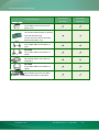
VXC/VEX Multi-Port Serial Card User Manual Version 1.7.1, Aug. 2014 WARRANTY VXC Series All products manufactured by ICP DAS are warranted against defective materials for a period of one year from the date of delivery to the original purchaser. Board includes VXC-112A, VXC-112U, VXC-112(i)AU WARNING ICP DAS assumes no liability for damages consequent to the use of this product. ICP DAS reserves the right to change this manual at any time without notice. The information furnished by ICP DAS is believed to be accurate and reliable. However, no VXC-114U, VXC-114iAU VXC-142(i), VXC-142(A)U, VXC-142i(A)U VXC-144U, VXC-144iU VXC-182i, VXC-182iAU responsibility is assumed by ICP DAS for its use, nor for any infringements of patents or other rights of third parties resulting from its use. COPYRIGHT Copyright © 2014 by ICP DAS. All rights are reserved. VEX Series TRADEMARK Names are used for identification only and may be registered trademarks of their respective companies. CONTACT US If you have any question, please feel to contact us. We will give Board includes VEX-112, VEX-112i VEX-114, VEX-114i you quick response within 2 workdays. VEX-142, VEX-142i Email: [email protected], [email protected] VEX-144, VEX-144i VXC/VEX Multi-Port Serial Card Table of Contents PACKING LIST........................................................................................................................................... 3 MORE INFORMATION .............................................................................................................................. 3 1. INTRODUCTION ............................................................................................................................. 4 1.1 1.2 1.3 2. FEATURES................................................................................................................................. 6 SPECIFICATIONS ......................................................................................................................... 9 OPTIONS ................................................................................................................................ 14 HARDWARE CONFIGURATION ....................................................................................................... 16 2.1 2.2 2.3 2.4 BOARD LAYOUT ....................................................................................................................... 16 SW1 DIP SWITCH (COM PORT MAPPING) .................................................................................... 18 WIRING NOTES FOR RS-232/422/485 ........................................................................................ 21 PIN ASSIGNMENTS ................................................................................................................... 23 3. HARDWARE INSTALLATION ........................................................................................................... 27 4. SOFTWARE INSTALLATION ............................................................................................................ 31 4.1 4.2 4.3 4.4 4.5 4.6 4.7 5. OBTAINING THE DRIVER INSTALLER PACKAGE .................................................................................. 31 INSTALLING VXCARD DRIVER UNDER WINDOWS .............................................................................. 32 PNP DRIVER INSTALLATION ........................................................................................................ 35 VERIFYING THE INSTALLATION ..................................................................................................... 37 CONFIGURATION COM PORT BUFFER SIZE ..................................................................................... 40 UNINSTALLING THE DEVICE DRIVER .............................................................................................. 41 INSTALLING VXCARD DRIVER UNDER LINUX .................................................................................... 42 TESTING THE VXC/VEX SERIES CARD ............................................................................................ 45 5.1 5.2 5.3 5.4 6. VXC/VEX-112/142 SERIES CARD WIRING ................................................................................... 45 VXC-182 SERIES CARD WIRING .................................................................................................. 47 VXC/VEX-114/144 SERIES CARD WIRING ................................................................................... 48 SELF-TEST .............................................................................................................................. 50 PROGRAMMING REFERENCE ....................................................................................................... 52 6.1 6.2 6.3 6.4 6.5 PCI HARDWARE IDS ................................................................................................................. 52 I/O ADDRESS MAPPING ............................................................................................................ 53 UART REGISTER ...................................................................................................................... 55 PROGRAMMABLE BAUD RATE ..................................................................................................... 56 CUSTOMIZED BAUD RATE .......................................................................................................... 58 ICP DAS CO., LTD. User Manual, Ver. 1.7.1, Aug. 2014 -2- VXC/VEX Multi-Port Serial Card Packing List The shipping package includes the following items: Note: If any of these items are missing or damaged, please contact the local distributor One VXC/VEX series Card One Quick Start Guide One Software Utility CD Quick Start for more information. Save the shipping materials and cartons in case you need to ship the module in the future. More Information Manual/DataSheet/QuickStart: CD:\NAPDOS\multiport\document http://ftp.icpdas.com/pub/cd/iocard/pci/napdos/multiport/document/ CD:\NAPDOS\multiport\manual CD:\NAPDOS\multiport\manual\quick_start http://ftp.icpdas.com/pub/cd/iocard/pci/napdos/multiport/manual/ http://ftp.icpdas.com/pub/cd/iocard/pci/napdos/multiport/manual/quick_start/ Software/Drivers: CD:\NAPDOS\multiport\windows CD:\NAPDOS\multiport\linux http://ftp.icpdas.com/pub/cd/iocard/pci/napdos/multiport/windows/ http://ftp.icpdas.com/pub/cd/iocard/pci/napdos/multiport/linux/ Software/Test2COM/Utility: CD:\NAPDOS\multiport\utility http://ftp.icpdas.com/pub/cd/iocard/pci/napdos/multiport/utility/ ICP DAS CO., LTD. User Manual, Ver. 1.7.1, Aug. 2014 -3- VXC/VEX Multi-Port Serial Card 1. Introduction The VXC/VEX multiport serial card enables user to increase additional communication ports on the PC. It’s the on-top-of-the-list choice while you are managing to connect lots of outer devices through your PC; every VXC/VEX card ensures you fluent communication in both time-critical applications and industrial fields. With simply a VXC/VEX card, it has never been that easy for integration of a PC with many other devices, like PLCs, FAB machines, meters, controller devices, laboratory instruments, modems, card readers, serial printers, RFID readers, bar code readers, sensors, etc. ICP DAS CO., LTD. User Manual, Ver. 1.7.1, Aug. 2014 -4- VXC/VEX Multi-Port Serial Card Comparison Table for VXC/VEX Series Cards: Model Bus RS-232 RS-422/ Self- RS-485 Tuner Isolation ESD Protection FIFO Size Connector (bytes) VEX-112 2 - - - - 128 Male DB-9 VEX-112i 2 - - 2.5 kV +/- 4 kV 128 Male DB-9 VEX-142 - 2 Yes - - 128 Male DB-9 - 2 Yes 2.5 kV +/- 4 kV 128 4 - - - - 128 VEX-114i 4 - - 2.5 kV +/- 4 kV 128 VEX-144 - 4 Yes - - 128 VEX-144i - 4 Yes 2.5 kV +/- 4 kV 128 Male DB-9 Female DB-37 Female DB-37 Female DB-37 Female DB-37 VXC-112U 2 - - - - 128 Male DB-9 VXC-112AU 2 - - - - 128 Male DB-9 VXC-112iAU 2 - - 2.5 kV +/- 4 kV 128 VXC-114U 4 - - - - 128 VXC-114iAU 4 - - 2.5 kV +/- 4 kV 128 Male DB-9 Female DB-37 Female DB-37 - 2 Yes - - 128 Male DB-9 - 2 Yes 2.5 kV +/- 4 kV 128 Male DB-9 - 2 Yes - - 128 Male DB-9 VXC-142iAU - 2 Yes 2.5 kV +/- 4 kV 128 VXC-144U - 4 Yes - - 128 VXC-144iU - 4 Yes 2.5 kV +/- 4 kV 128 Male DB-9 Female DB-37 Female DB-37 VXC-182iU 1 1 Yes 2.5 kV +/- 4 kV 128 Male DB-9 VXC-182iAU 1 1 Yes 2.5 kV +/- 4 kV 128 Male DB-9 VXC-112A 2 - - - - 128 Male DB-9 - 2 Yes - - 128 Male DB-9 - 2 Yes 2.5 kV +/- 4 kV 128 Male DB-9 1 1 Yes 2.5 kV +/- 4 kV 128 Male DB-9 VEX-142i VEX-114 VXC-142U VXC-142iU VXC-142AU VXC-142 VXC-142i PCI Express Universal PCI PCI Bus VXC-182i ICP DAS CO., LTD. User Manual, Ver. 1.7.1, Aug. 2014 -5- VXC/VEX Multi-Port Serial Card 1.1 Features PCI Express PCI Express (PCIe) is a computer expansion card standard. A key difference between PCIe and earlier PC buses is a topology based on point-to-point serial links, rather than shared parallel bus architecture. Concep-tually, the PCIe bus can be thought of as a 'high-speed serial replacement' of the older PCI/PCI-X bus. Universal PCI (3.3 V and 5 V) The Universal PCI card works with both the newer 3.3 V PCI bus that is widely-used in servers, and the traditional 5 V PCI bus. The Universal PCI interface will be the standard for every card developed by ICP DAS in the near future. COM-Selector Each VXC/VEX card is equipped with a COM-Selector (Dip Switch) for the COM port number selection (automatically or manually). It’s an important and innovative feature for the VXC/VEX family. The COM-Selector provides the following advantages: Simplifies the COM port number selection instead of using configuration utility programs. Users can specify the COM port number of the VXC/VEX card as exactly what they want, no matter which PCI slot it is located at. Automatically select an available COM port number is supported by setting the COMSelector (dip switch) to 0 (default). No need to install configuration utility and to study its operation for different OS. Prevents confusion. Other PnP COM port devices easily confuse users because of adopting the dynamic COM port number setting. Easy replacement of an existing card by setting the dip-switch to be the same COM port number. Great for mass system installation, since setting the dip-switch to be the same COM port number is very easy. ICP DAS CO., LTD. User Manual, Ver. 1.7.1, Aug. 2014 -6- VXC/VEX Multi-Port Serial Card ESD Protection The VXC/VEX cards offer TVS diode ESD protection technology, protecting your system from being damaged by the high potential voltages. Under normal operating conditions, the TVS diode presents high impedance (appears as an open circuit) to the protected component. When the voltage is beyond the limits, the TVS diode avalanches providing a low impedance path for the transient current. As a result, the transient current is diverted away from the protected components and shunted through the TVS diode. The device returns to a high impedance state after the transient threat passes. Hardware FIFO up To 128 Bytes The VXC/VEX cards offer TVS diode ESD protection technology, protecting your system from being damaged by the high potential voltages. VXC/VEX series cards are equipped with a large 16-byte or 128-byte hardware FIFO for each port. A large hardware FIFO is useful for preventing data loss if the loading on your system is heavy, e.g. while you are running a multi-task operating system, such as Windows, or Linux, etc. Up To 128 KB COM Port Buffer The VXC/VEX card driver for Windows features a 128 KB maximum software FIFO for each port (default is 4 KB). It’s practical for large file transmission. ICP DAS CO., LTD. User Manual, Ver. 1.7.1, Aug. 2014 -7- VXC/VEX Multi-Port Serial Card Self-Tuner The VXC/VEX series cards are equipped with an internal “Self-Tuner” chip that is used to automatically control the direction of the transmission and receiving of signals on the RS-485 ports. Without the inclusion of the Self-Tuner, the RS-485 transmitter would need to be manually enabled before transmitting, and then disabled once the transmission is complete. The timing method that is used to enable and disable the transmitter (direction control) is a major source of many communication problems, and is very difficult to rectify. The built-in Self-Tuner embedded on the VXC/VEX series cards can help effectively eliminate any issues related to direction control and also simplifies the software programming required for communication applications. Isolation Some VXC/VEX cards offer photo isolation to protect your computer and equipment against damages in harsh environment. Photo coupler is a device that uses a short optical transmission path to transfer a signal between elements of a circuit, typically a transmitter and a receiver. This keeping them electrically isolated — since the signal goes from an electrical signal to an optical signal, the electrical contact along the path is broken. It can help cutting down on ground loops, common mode voltages and block voltage spikes, provide electrical isolation, and offer significant protection from serious over-voltage conditions in one circuit affecting the other. Various Accessories There are a lot of optional accessories for the VXC/VEX series cards, such as RS-232 cables and daughter boards. These tools make wiring much easily than ever. ICP DAS CO., LTD. User Manual, Ver. 1.7.1, Aug. 2014 -8- VXC/VEX Multi-Port Serial Card 1.2 Specifications 1.2.1 VXC/VEX-112 Series Models VXC-112U VXC-112AU VXC-112A VXC-112iAU VEX-112 VEX-112i Communication Port COM1 - COM2 RS-232 (TxD, RxD, RTS, CTS, DTR, DSR, DCD, RI, GND) 16c550 compatible UART Baud Rate Data Bits Stop Bits Parity 50 - 115200 bps 5, 6, 7, 8 1, 1.5, 2 None, Even, Odd, Mark, Space Internal 16 bytes - FIFO Isolated General Bus Type PCI, 5 V, 33 MHz, 32-bit, Plug and Play COM-Selector Connector Power Consumption 105 mA @ 5 V Operating Temperature Storage Temperature Humidity Dimensions (L x W x D) ICP DAS CO., LTD. 16c950 compatible 130 mm x 105 mm x 22 mm Internal 128 bytes - 2500 VDC - 2500 VDC Universal PCI, PCI Express x1, 3.3 V/5 V, 33 MHz, 32-bit, Plug and Play Plug and Play Yes (8-bit DIP Switch) 2 x DB9 (Male) 480 mA @ 5 120 mA @ 440 mA @ 100 mA @ 5 V V 5V 5V 0°C ~ +60°C -20°C ~ +70°C 0 ~ 90% RH, non-condensing 110 mm x 94 mm x 22 134 mm x 90 mm x 22 mm mm User Manual, Ver. 1.7.1, Aug. 2014 -9- VXC/VEX Multi-Port Serial Card 1.2.2 VXC/VEX-114 Series Models VXC-114U VXC-114iAU VEX-114 VEX-114i Communication Port COM1 - COM4 UART Baud Rate Data Bits Stop Bits Parity FIFO Isolated General Bus Type COM-Selector Connector Power Consumption Operating Temperature Storage Temperature Humidity Dimensions (L x W x D) ICP DAS CO., LTD. RS-232 (TxD, RxD, RTS, CTS, DTR, DSR, DCD, RI, GND) - 16c950 compatible 50 ~ 115200 bps 5, 6, 7, 8 1, 1.5, 2 None, Even, Odd, Mark, Space Internal 128 bytes 2500 VDC - -2500 VDC Universal PCI, PCI Express x1, 3.3 V/5 V, 33 MHz, Plug and Play 32-bit, Plug and Play Yes (8-bit DIP Switch) DB-37 (Female) 120 mA @ 5 V 880 mA @ 5 V 120 mA @ 5 V 880 mA @ 5 V 0°C ~ +60°C -20°C ~ +70°C 0 ~ 90% RH, non-condensing 142 mm x 84 mm x 133 mm x 93 mm x 110 mm x 110 mm x 22 mm 22 mm 22 mm User Manual, Ver. 1.7.1, Aug. 2014 - 10 - VXC/VEX Multi-Port Serial Card 1.2.3 VXC/VEX-142 Series Models VXC-142 VXC-142i VXC-142U VXC-142AU VXC-142iU VXC-142iAU VEX-142 VEX-142i Communication Port RS-422/485 RS-422 COM1COM2 RS-485 2-Wire Bias Resistor Nodes UART Baud Rate Data Bits Stop Bits Parity FIFO Isolated General Bus Type The RS-422 and RS-485 interfaces cannot be used simultaneously. RS-422 (TxD+, TxD-, RxD+, RxD-, RTS+, RTS-, CTS+, CTS-, GND) RS-485 (Data+, Data-, GND) Yes, 1 KΩ 16c550 compatible Internal 16 bytes 3000 VDC PCI, 5 V, 33 MHz, 32-bit, Plug and Play COM-Selector Connector Power Consumption 105 mA @5V 500 mA @5V 130 mm x 105 mm x 22 mm 140 mm x 95 mm x 22 mm Operating Temperature Storage Temperature Humidity Dimensions (L x W x D) ICP DAS CO., LTD. 256 (max.) 16c950 compatible 50 ~ 115200 bps 5, 6, 7, 8 1, 1.5, 2 None, Even, Odd, Mark, Space Internal 128 bytes 2500 VDC Universal PCI, 3.3 V/5 V, 33 MHz, 32-bit, Plug and Play Yes (8-bit DIP Switch) 2 x DB9 (Male) 100 mA @ 5 480 mA @ 5 V V 0°C ~ +60°C -20°C ~ +70°C 0 ~ 90% RH, non-condensing 134 mm x 90 mm x 22 mm 2500 VDC PCI Express x1, Plug and Play 120 mA @5V 440 mA @5V 110 mm x 94 mm x 22 mm User Manual, Ver. 1.7.1, Aug. 2014 - 11 - VXC/VEX Multi-Port Serial Card 1.2.4 VXC/VEX-144 Series Models Communication Port RS-422/485 RS-422 COM12-Wire COM4 RS-485 Bias Resistor VXC-144U Bus Type COM-Selector Connector Power Consumption Operating Temperature Storage Temperature Humidity Dimensions (L x W x D) ICP DAS CO., LTD. VEX-144 VEX-144i The RS-422 and RS-485 interfaces cannot be used simultaneously. RS-422 (TxD+, TxD-, RxD+, RxD-, RTS+, RTS-, CTS+, CTS-, GND) RS-485 (Data+, Data-, GND) Nodes UART Baud Rate Data Bits Stop Bits Parity FIFO Isolated General VXC-144iAU - Yes, 1 KΩ 256 (max.) 16c950 compatible 50 ~ 115200 bps 5, 6, 7, 8 1, 1.5, 2 None, Even, Odd, Mark, Space Internal 128 bytes 2500 VDC - -2500 VDC Universal PCI, PCI Express x1, 3.3 V/5 V, 33 MHz, 32-bit, Plug and Play Plug and Play Yes (8-bit DIP Switch) DB-37 (Female) 120 mA @ 5 V 880 mA @ 5 V 120 mA @ 5 V 880 mA @ 5 V 0°C ~ +60°C -20°C ~ +70°C 0 ~ 90% RH, non-condensing 142 mm x 84 142 mm x 95 114 mm x 101 mm x 22 mm mm x 22 mm mm x 22 mm User Manual, Ver. 1.7.1, Aug. 2014 - 12 - VXC/VEX Multi-Port Serial Card 1.2.5 VXC-182 Series Models VXC-182iU VXC-182iAU VXC-182i Communication Port RS-422/485 RS-422 COM1 2-Wire RS-485 The RS-422 and RS-485 interfaces cannot be used simultaneously. RS-422 (TxD+, TxD-, RxD+, RxD-, RTS+, RTS-, CTS+, CTS-, GND) RS-485 (Data+, Data-, GND) Bias Resistor Yes, 1 KΩ Nodes 256 (max.) COM2 UART Baud Rate Data Bits Stop Bits Parity FIFO Isolated General Bus Type COM-Selector Connector Power Consumption Operating Temperature Storage Temperature Humidity Dimensions (L x W x D) ICP DAS CO., LTD. RS-232 (TxD, RxD, RTS, CTS, DTR, DSR, DCD, RI, GND) 16c950 compatible 50 ~ 115200 bps 5, 6, 7, 8 1, 1.5, 2 None, Even, Odd, Mark, Space Internal 128 bytes 2500 VDC for RS-422/485 port PCI, 5 V, Universal PCI, 33 MHz, 32-bit, 3.3 V/5 V, 33 MHz, 32-bit, Plug and Play Plug and Play Yes (8-bit DIP Switch) 2 x DB9 (Male) 200 mA @ 5 V 0°C ~ +60°C -20°C ~ +70°C 0 ~ 90% RH, non-condensing 134 mm x 90 mm x 22 mm User Manual, Ver. 1.7.1, Aug. 2014 - 13 - VXC/VEX Multi-Port Serial Card 1.3 Options Item & Description CA-PC09F 9-pin Female Dsub connector with plastic cover DN-09-2/ DN-09-2F I/O Connector Block with DINRail Mounting and two 9-Pin male Header CA-0910F 9-pin FemaleFemale D-sub Cable, 1 m CA-0910N 9-pin FemaleFemale D-sub Cable, 1 m Null Modem Cable CA-0915 9-pin MaleFemale D-sub Cable, 1.5 m CA-090910 9-pin Female Dsub & (9-wire) RS-422 Cable, 1 m CA-0903 9-pin Female Dsub & 5-wire RS232 Cable, 30 cm CA-0910 9-pin Female Dsub & 3-wire RS232 Cable, 1 m ICP DAS CO., LTD. VXC-112 series VXC-182 series VXC-142 series VEX-112 series VEX-142 series - - - - - - - - - - User Manual, Ver. 1.7.1, Aug. 2014 - 14 - VXC/VEX Multi-Port Serial Card Item & Description CA-4002 37-pin Male D-sub connector with plastic cover DN-37 I/O Connector Block (Pitch= 5.08 mm) with DIN-Rail Mounting Include: One CA-3710 (37-pin MaleMale D-sub Cable 1.0 m) CA-3710 37-Pin Male-Male D-sub Cable 1 m (45º) CA-3710D 37-Pin Male-Male D-sub Cable 1 m (180º) CA-3720 DB-37 Male-Male D-sub Cable 2 m Cable(45 º) CA-3720D 37-Pin Male-Male D-sub Cable 2 m (180º) CA-9-3715D DB-37 Male(D-sub) to 4-Port DB-9 Male(D-sub) Cable 1.5 M (180 º) ICP DAS CO., LTD. VXC-114(iA)U VXC-144(i)U VEX-114(i) VEX-144(i) User Manual, Ver. 1.7.1, Aug. 2014 - 15 - VXC/VEX Multi-Port Serial Card 2. Hardware Configuration 2.1 Board Layout VXC-114/144 series: SW1 CON1 CON1 VXC-112/142/182 series: SW1 CON1 CON2 ICP DAS CO., LTD. User Manual, Ver. 1.7.1, Aug. 2014 - 16 - VXC/VEX Multi-Port Serial Card VEX-114/144 series: SW1 CON1 VEX-112/142 series: SW1 CON1 CON2 ICP DAS CO., LTD. User Manual, Ver. 1.7.1, Aug. 2014 - 17 - VXC/VEX Multi-Port Serial Card 2.2 SW1 DIP Switch (COM Port Mapping) The Board ID and COM port mapping are the same, which is set by the SW1 DIP Switch. The SW1 DIP Switch has different functions under different OS. For DOS users, the SW1 DIP switch acts as Board ID. When there are two or more multi-port serial cards in a single system, it is difficult to identify individual card number. For easier identification, the VXC/VEX series card includes a Board ID function. For Windows users, the SW1 DIP switch acts as COM port number selector and the COM port number is depending on the Board ID. If the Board ID is 0, then the driver finds a valid number for each port. If the Board ID is not 0, then the driver uses the “Board ID” to be the first COM port number and uses the “Board ID +1” to be the next COM port number and so on. For Linux users, it’s the same as Windows users but for TTY device number selector. Note: It’s recommended to select a unique COM port number (Board ID) by users. This helps users to clear identify and fix the card-number and port-number in a system. Warning: The port will not work if the COM port number is conflicted under Windows or Linux system. In that case, users should try other COM port numbers. Usually, the COM1 and COM2 are reserved by systems. And it’s recommended to reserve the COM3 and COM4 if you will have other Plug&Play serial ports in the future. This prevents conflict. ICP DAS CO., LTD. User Manual, Ver. 1.7.1, Aug. 2014 - 18 - VXC/VEX Multi-Port Serial Card 2.2.1 VXC/VEX-112/142/182 Series cards The COM port mapping configuration examples are as follows: If Setting SW1 dip-switch (COM Selector) to 0x05 (1 and 3 “NO1”, others “OFF0”).The setting forces the 2-port VXC/VEX series card to use COM5 and COM6. SW1 Setting Table for the VXC/VEX-112/142/182 Series (2-Port): SW1 DIP Switch Board ID= 0x00 (Default) COM = Auto-defined Bard ID= 0x03 COM= 3/4 Bard ID= 0x05 COM= 5/6 Bard ID= 0x07 COM= 7/8 Bard ID= 0x09 COM= 9/10 Bard ID= 0x14 COM= 20/21 Bard ID= 0x1E COM= 30/31 Bard ID= 0x28 COM= 40/41 Bard ID= 0x32 COM= 50/51 Bard ID= 0x3C COM= 60/61 Bard ID= 0x64 COM= 100/101 . . . Bard ID= 0xFF COM= 255/256 ICP DAS CO., LTD. 8 7 6 5 4 3 2 1 OFF OFF OFF OFF OFF OFF OFF OFF OFF OFF OFF OFF OFF OFF ON ON OFF OFF OFF OFF OFF ON OFF ON OFF OFF OFF OFF OFF ON ON ON OFF OFF OFF OFF ON OFF OFF ON OFF OFF OFF ON OFF ON OFF OFF OFF OFF OFF ON ON ON ON OFF OFF OFF ON OFF ON OFF OFF OFF OFF OFF ON ON OFF OFF ON OFF OFF OFF ON ON ON ON OFF OFF OFF ON ON OFF OFF ON OFF OFF . . . . . . . . . . . . . . . . . . . . . . . . ON ON ON ON ON ON ON ON User Manual, Ver. 1.7.1, Aug. 2014 - 19 - VXC/VEX Multi-Port Serial Card 2.2.2 VXC/VEX-114/144 Series cards The COM port mapping configuration examples are as follows: If Setting SW1 dip-switch (COM Selector) to 0x05 (1 and 3 “NO1”, others “OFF0”). The setting forces the 4-port VXC/VEX series card to use COM5, COM6, COM7 and COM8. SW1 Setting Table for the VXC/VEX-114/144 Series (4-Port): SW1 DIP Switch Board ID= 0x00 (Default) COM = Auto-defined Bard ID= 0x03 COM= 3/4/5/6 Bard ID= 0x05 COM= 5/6/7/8 Bard ID= 0x07 COM= 7/8/9/10 Bard ID= 0x09 COM= 9/10/11/12 Bard ID= 0x14 COM= 20/21/22/23 Bard ID= 0x1E COM= 30/31/32/33 Bard ID= 0x28 COM= 40/41/42/43 Bard ID= 0x32 COM= 50/51/52/53 Bard ID= 0x3C COM= 60/61/62/63 Bard ID= 0x64 COM= 100/101/102/103 Bard ID= 0x96 COM= 150/151/152/153 Bard ID= 0xC8 COM= 200/201/202/203 . . Bard ID= 0xFF COM= 255/256/x/x ICP DAS CO., LTD. 8 7 6 5 4 3 2 1 OFF OFF OFF OFF OFF OFF OFF OFF OFF OFF OFF OFF OFF OFF ON ON OFF OFF OFF OFF OFF ON OFF ON OFF OFF OFF OFF OFF ON ON ON OFF OFF OFF OFF ON OFF OFF ON OFF OFF OFF ON OFF ON OFF OFF OFF OFF OFF ON ON ON ON OFF OFF OFF ON OFF ON OFF OFF OFF OFF OFF ON ON OFF OFF ON OFF OFF OFF ON ON ON ON OFF OFF OFF ON ON OFF OFF ON OFF OFF ON OFF OFF ON OFF ON ON OFF ON ON OFF OFF ON OFF OFF OFF . . . . . . . . . . . . . . . . ON ON ON ON ON ON ON ON User Manual, Ver. 1.7.1, Aug. 2014 - 20 - VXC/VEX Multi-Port Serial Card 2.3 Wiring Notes for RS-232/422/485 2.3.1 RS-232 Wiring Notes: 1. For 3-wire RS-232 connection, it’s recommended to short unused signals such as RTS/CTS and DTR/DSR, since some systems may still check the CTS and DSR status. 2. FGND is the frame ground that is soldered to the metal shield on the DB-9 cable. ICP DAS CO., LTD. User Manual, Ver. 1.7.1, Aug. 2014 - 21 - VXC/VEX Multi-Port Serial Card 2.3.2 RS-422/485 Wiring RS-485 wiring: RS-422 wiring: Notes: 1. Usually, you have to connect all signal grounds of RS-422/485 devices together to reduce common-mode voltage between devices. 2. Twisted-pair cable must be used for the DATA+/- wires. 3. Both two ends of the cable may require a termination resistor connected across the two wires (DATA+ and DATA-). Typically 120 Ω resisters are used. 4. The Data+ and B pins are positive-voltage pins, and Data- and A pins are negative-voltage pins in the above figure. The B/A pins may be defined in another way depending on devices, please check it first. ICP DAS CO., LTD. User Manual, Ver. 1.7.1, Aug. 2014 - 22 - VXC/VEX Multi-Port Serial Card 2.4 Pin Assignments 2.4.1 VXC/VEX-112 Series 2.4.2 VXC/VEX-142 Series ICP DAS CO., LTD. User Manual, Ver. 1.7.1, Aug. 2014 - 23 - VXC/VEX Multi-Port Serial Card 2.4.3 VXC/VEX-114 Series ICP DAS CO., LTD. User Manual, Ver. 1.7.1, Aug. 2014 - 24 - VXC/VEX Multi-Port Serial Card 2.4.4 VXC/VEX-144 Series ICP DAS CO., LTD. User Manual, Ver. 1.7.1, Aug. 2014 - 25 - VXC/VEX Multi-Port Serial Card 2.4.5 VXC-182 Series CON1: Isolation RS-422/485 Port: CON2: RS-232 Port: ICP DAS CO., LTD. User Manual, Ver. 1.7.1, Aug. 2014 - 26 - VXC/VEX Multi-Port Serial Card 3. Hardware Installation Notes: 1. As certain operating systems, such as Windows 2000/XP may require the computer to be restarted after a new driver is installed, it is recommended that the driver is installed first, which will reduce the installation time. 2. Static electricity can easily damage computer equipment. It is recommended that your ground yourself by touching the chassis of the computer before handling any of the boards. Follow the process described below to install your VXC/VEX series card: Step 1: Install the VXC/VEX series card driver on your computer. For detailed information regarding driver installation, refer to Chapter 4 Software Installation. Step 2: Configuring COM port mapping (board ID) by the SW1 DIP-Switch. For detailed information regarding the COM port mapping (board ID), refer to Sec. 2.2 SW1 DIP Switch (COM Port Mapping). ICP DAS CO., LTD. User Manual, Ver. 1.7.1, Aug. 2014 - 27 - VXC/VEX Multi-Port Serial Card Step 3: Correctly shut down and power off your computer, and then disconnect the power supply Step 4: Remove the cover from the computer. Step 5: Select an empty PCI/PCI Express slot. ICP DAS CO., LTD. User Manual, Ver. 1.7.1, Aug. 2014 - 28 - VXC/VEX Multi-Port Serial Card Step 6: Remove the screw holding the cover for the PCI/PCI Express slot in place and then remove the slot cover from the PC. Ensure that you do not misplace the screw. Step 7: Remove the connector cover form the VXC/VEX series card. Step 8: Align the contacts of the PCI/PCI Express card with the open slot on your motherboard and carefully insert your VXC/VEX series card into the PCI/PCI Express slot. ICP DAS CO., LTD. User Manual, Ver. 1.7.1, Aug. 2014 - 29 - VXC/VEX Multi-Port Serial Card Step 9: Screw the mounting bracket screw removed in step 5 into the new PCI/PCI Express card bracket to secure the card in place. Confirm that the VXC/VEX series card is correctly mounted on the motherboard. Step 10: Re-attach cover for the computer and reconnect the power supply. Step 11: Power on the computer. Once the computer reboots, follow the onscreen messages to complete the Plug & Play installation process. For more information, refer to Chapter 4 Software Installation. ICP DAS CO., LTD. User Manual, Ver. 1.7.1, Aug. 2014 - 30 - VXC/VEX Multi-Port Serial Card 4. Software Installation The VXC/VEX series card can be used with both DOS, Linux and Windows 2000 and 32/64-bit Windows XP/2003/2008/Vista32/Windows 7 systems, and also supports Plug & Play functions for easy installation. This chapter provides a detailed description of how to install the drivers for the VXC/VEX series card. 4.1 Obtaining the Driver Installer Package The installer package for the ICP DAS VXC/VEX series driver can be obtained from either the companion CD-ROM, the FTP site, or the ICP DAS web site. The locations and addresses are show below: CD:\\ NAPDOS\MultiPort\Windows\ ftp://ftp.icpdas.com/pub/cd/iocard/pci/napdos/multiport/ http://ftp.icpdas.com/pub/cd/iocard/pci/napdos/multiport/ Install the appropriate driver for your operating system, as follows: Folder Setup File Windows VxCardWin32_64_x_ xx_xx.exe OS for Windows 2000/XP/2003/2008/Vista and Windows 7(32/64-bit) For detailed information about the Windows driver installation, please refer to section 4.2. for Linux 2.4.X/2.6.X/3.12.X Linux ixcom.tar.gz For detailed information about the Linux driver installation, please refer to section 4.7. DOS DOS Library files ICP DAS CO., LTD. for DOS User Manual, Ver. 1.7.1, Aug. 2014 - 31 - VXC/VEX Multi-Port Serial Card 4.2 Installing VxCard Driver under Windows Follow the process described below to set up the software for the VXC/VEX series card: Step 1: Double Click the “VxCardWin32_64_x_xx_xx.exe” to install the driver. Step 2: When the setup Wizard screen is displayed, click the “Next>” button to begin the installation. ICP DAS CO., LTD. User Manual, Ver. 1.7.1, Aug. 2014 - 32 - VXC/VEX Multi-Port Serial Card Step 3: Select the folder where the drivers are to be install. The default path is C:\ICPDAS\VxCard_Win32_64, but if your wish to install the drivers to a different location, click the “Browse…” button and select the relevant folder and then click then “Next>” button. 1 2 Note: More recent operating system, such as Windows Vista/7, will display a warning message asking you to confirm that your wish to install the device software, refer to figure below. Step 1: In the “Windows Security” dialog box, check the “Always trust software from “ICP DAS Co., LTD.” Checkbox. Step 2: Click the “Install” button. This warning will be displayed several times. In all cases, click the “Install” button to proceed with the installation. ICP DAS CO., LTD. User Manual, Ver. 1.7.1, Aug. 2014 - 33 - VXC/VEX Multi-Port Serial Card Step 4: Once the driver has been installed, the Setup Wizard will be displayed to advise that the computer must be restarted in order to complete the installation. In the installation process, the Command Prompt windows will be displayed, don't care. Please do not close this window in installation process. Select the “No, I will restart 1 the computer later” option, and then click the “Finish” button to exit the Wizard. 2 ICP DAS CO., LTD. User Manual, Ver. 1.7.1, Aug. 2014 - 34 - VXC/VEX Multi-Port Serial Card 4.3 PnP Driver Installation Step 1: Correctly shut down and power off your computer and disconnect the power supply, and then install the VXC/VEX series card into the computer. For detailed information regarding installation of the VXC/VEX series card, refer to Chapter 3 Hardware Installation. Step 2: Power on the computer and complete the Plug & Play installation. Note: More recent operating system, such as Windows Vista/7, will automatically detect the new hardware and install the necessary drivers etc., so Steps 3 to 5 can be skipped. Step 3: When the “Found New Hardware Wizard” is displayed, select “Install the software automatically [Recommended]” option and then click the “Next>” button. ICP DAS CO., LTD. User Manual, Ver. 1.7.1, Aug. 2014 - 35 - VXC/VEX Multi-Port Serial Card Step 4: The “Found New Hardware Wizard” will be displayed to advise that the software installation has been completed. Click the “Finish” button to exit the Wizard. Step 5: If the “Found New Hardware Wizard” dialog box is displayed again, repeat Steps 3 and 4 to complete the installation for all COM ports. ICP DAS CO., LTD. User Manual, Ver. 1.7.1, Aug. 2014 - 36 - VXC/VEX Multi-Port Serial Card 4.4 Verifying the Installation To verify the installation, use the Windows Device Manager to view and update the device drivers installed on your computer, and check to ensure that hardware is operating correctly. The following is a description of how access the Device Manager in each of the major versions of Windows. Refer to the appropriate description for your specific operating system to verify the installation. 4.4.1 How do I access Windows Device Manager? Microsoft Windows 2000/XP Step 1: Click “Start” then point to “Settings” and click “Control Panel”. Double-click the “System” icon to open the “System Properties” dialog box. Step 2: Click the “Hardware” tab, and then click the “Device Manager” button. ICP DAS CO., LTD. User Manual, Ver. 1.7.1, Aug. 2014 - 37 - VXC/VEX Multi-Port Serial Card Microsoft Windows Server 2003/2008 Step 1: Click “Start” point to “Administrative Tools”, and then click “Computer Management”. Step 2: From “System Tools” in the console tree, click “Device Manager”. Microsoft Windows Vista/7 Step 1: Click “Start” button, and then click “Control Panel”. Step 2: Click “System and Maintenance”, and then click “Device Manager”. Alternatively, Step 1: Click “Start” button. Step 2: In the Search field, type Device Manager and the press Enter. Note that Administrator privileges are required for this operation. If you are prompted for an administrator password or confirmation, type the password or provide confirmation. ICP DAS CO., LTD. User Manual, Ver. 1.7.1, Aug. 2014 - 38 - VXC/VEX Multi-Port Serial Card 4.4.2 Check the Configuration of the COM Port Step 3: Verify that the COM ports for the VXC/VEX series card are listed correctly. Successful installation ICP DAS CO., LTD. User Manual, Ver. 1.7.1, Aug. 2014 - 39 - VXC/VEX Multi-Port Serial Card 4.5 Configuration COM Port Buffer Size The VXC/VEX series driver includes a VxCard Utility that allows the users can change the input buffer size (default is 4 KB for each port, up to 128 KB) by setting the “SW FIFO” scroll-bar on the VxCard Utility. The VxCard Utility can be found in the the driver installation folder, for example C:\ICPADS\VxCard_Win32_64. Note: If necessary, the COM port mapping can be adjusted, refer to the following: Step 1: Change the COM port mappings (see Section 2.2 SW1 DIP Switch (COM Port Mapping). Step 2: Restart the driver by rebooting the computer. or Step 2: Re-install the “VXC/VEX Card” hardware in the “Device Manager” by un-install card and then scan new hardware. ICP DAS CO., LTD. User Manual, Ver. 1.7.1, Aug. 2014 - 40 - VXC/VEX Multi-Port Serial Card 4.6 Uninstalling the Device Driver The VXC/VEX series driver includes a uninstall driver utility that allows the software to be removed from your computer. To uninstall the software, follow the process described below: Step 1: Open the driver installation folder, for example C:\ICPADS\VxCard_Win32_64, and then double-click the unins000.exe uninstaller application. Step 2: The uninstaller application will then ask you to confirm that you wish to remove the utility program. Click the “Yes” button to continue. Step 3: The “Remove Shard File?” dialog box will be displayed asking whether your wish to remove the shared file. Click the “Yes to All” button to continue. Step 4: After the uninstallation process is complete, a dialog box will be displayed to notify that the driver was successfully removed. Click the “OK” button to finish. ICP DAS CO., LTD. User Manual, Ver. 1.7.1, Aug. 2014 - 41 - VXC/VEX Multi-Port Serial Card 4.7 Installing VxCard Driver under Linux This section describes VXC/VEX series card Linux driver’s features and how to compile and install into a general Linux system (Linux kernel 2.4.X, 2.6.X or 3.12.X). The VXC/VEX series card Linux driver is modified from Linux kernel source and supports most of popular PC-based Linux distributions. 4.7.1 Driver Features Device file. Dynamic device allocation. Dynamic major number. One major number for multiple devices. Use the GNU configure and build system. 4.7.2 Installation To install Linux driver, complete the following steps: Step 1: Download or copy the IxCOM package to a directory that you have access to. Please refer to section 4.1 “Obtaining the Driver Installer Package” getting the location of IxCOM package. Step 2: Extract the IxCOM package. For example, the package's file name is "ixcom-0.8.1.tar.gz" and its path related to your current working directory is.../pkg, then the extraction command would be #tar -zxvf ../pkg/ixcom-0.8.1.tar.gz An ixcom-0.8.1 directory is created after extraction. ICP DAS CO., LTD. User Manual, Ver. 1.7.1, Aug. 2014 - 42 - VXC/VEX Multi-Port Serial Card Step 3: For convenient access, it is a good idea to put a symbol-link on it. #ln -s ixcom-0.8.1 ixcom Step 4: Change to the ixcom working directory you just made, type #./configure to create proper Makefiles. Step 5: Once the configuring has done successfully, type “make” to build all. Note: If you like to install files to system directory, the make install will do it for you. However, install files to system directory is not necessary for further operation. You will need the root privilege for that. Script “./ixcom.inst” loads modules automatically. Script “./ixcom.remove” removes the loaded modules. The root privilege is required when installing or removing these kernel modules. 4.7.3 Access to VXC/VEX Serial Port Script “ixcom.inst” will establish unused device major number dynamically and create correspond device node for access VXC/VEX serial port. # ./ixcom.inst IxCOM Installer 0.5.0 Check kernel version... 2.6 Use proc-file /proc/icpdas/ixcom Load module ixcom ICP DAS CO., LTD. User Manual, Ver. 1.7.1, Aug. 2014 - 43 - VXC/VEX Multi-Port Serial Card Use “dmesg” command to inspect the driver output message. dmesg ……… ……… ICPDAS VXC multi-serial card Serial driver version ixcom-0.8.1 (2007-08-21) Found ICPDAS VXC-114U series board(BusNo=0,DevNo=20) PCI: Found IRQ 11 for device 0000:00:14.0 PCI: Sharing IRQ 11 with 0000:00:07.2 PCI: Sharing IRQ 11 with 0000:00:14.1 ttySV0 at port cc00 (irq = 11) is a 16C950/954 ttySV1 at port d000 (irq = 11) is a 16C950/954 ttySV2 at port d400 (irq = 11) is a 16C950/954 ttySV3 at port d800 (irq = 11) is a 16C950/954 The script “ixcom.inst” had loaded module into kernel and find a VXC/VEX card that have four serial port, ttySV0, ttySV1, ttySV2 and ttySV3. The “ixcom.inst” script will use major number 254 to create correspond device on the /dev. # ls -la /dev/ttySV? crw-rw-rw- 1 root crw-rw-rw- 1 root crw-rw-rw- 1 root crw-rw-rw- 1 root crw-rw-rw- 1 root crw-rw-rw- 1 root crw-rw-rw- 1 root crw-rw-rw- 1 root crw-rw-rw- 1 root crw-rw-rw- 1 root root root root root root root root root root root 254, 254, 254, 254, 254, 254, 254, 254, 254, 254, 64 Jul 14 10:13 /dev/ttySV0 65 Jul 14 10:13 /dev/ttySV1 66 Jul 14 10:13 /dev/ttySV2 67 Jul 14 10:13 /dev/ttySV3 68 Jul 14 10:13 /dev/ttySV4 69 Jul 14 10:13 /dev/ttySV5 70 Jul 14 10:13 /dev/ttySV6 71 Jul 14 10:13 /dev/ttySV7 72 Jul 14 10:13 /dev/ttySV8 73 Jul 14 10:13 /dev/ttySV9 To remove VXC/VEX driver from system use script “./ixcom.remove” to removes the loaded modules. ICP DAS CO., LTD. User Manual, Ver. 1.7.1, Aug. 2014 - 44 - VXC/VEX Multi-Port Serial Card 5. Testing the VXC/VEX Series Card This chapter provides detailed information about regarding the “self-test” process which enables the user to confirm whether or not the VXC/VEX series card is operating correctly. Before performing the “self-test” the hardware and driver installation must be completed. For detailed information regarding hardware and driver installation, refer to Chapter 3 Hardware Installation and Chapter 4 Software Installation. 5.1 VXC/VEX-112/142 Series Card Wiring Preparing the Device Before beginning the “Self-test”, ensure that following items are available: A DN-09-2 (optional) terminal board Two CA-0910F (optional) cables Step 1: Connect the DN-09-2 terminal board to the VXC/VEX-112 or VXC/VEX-142 series card using CA-0910F cable. DN-09-2 ICP DAS CO., LTD. VXC/VEX-112 series card VXC/VEX-142 series card User Manual, Ver. 1.7.1, Aug. 2014 - 45 - VXC/VEX Multi-Port Serial Card VXC/VEX-112 Series Card (RS-232): CON2 Pin Assignment Pin No. Pin No. CON1 Pin Assignment TxD 3 2 RxD RxD 2 3 TxD Step 2: Perform the “self-test” by shorting the RxD and TxD pins of both CON1 and CON2 connectors. VXC/VEX-142 Series Card (RS-485): CON2 Pin Assignment Pin No. Pin No. CON1 Pin Assignment Data- 1 1 Data- Data+ 2 2 Data+ Step 2: Perform the “self-test” by shorting the CON2 Data+ and CON1 Data+ and CON2 Data- and CON1 Data- pins. Note: For detailed information regarding wiring and pin assignments for the RS-232/422/485, refer to Section 2.3 Wiring Notes for RS-232/422/485 and Section 2.4 Pin Assignments. ICP DAS CO., LTD. User Manual, Ver. 1.7.1, Aug. 2014 - 46 - VXC/VEX Multi-Port Serial Card 5.2 VXC-182 Series Card Wiring Preparing the Device Before beginning the “Self-test”, ensure that following items are available: A DN-09-2 (optional) terminal board A i-7250 (optional) Isolated RS-232 to Rs-485 converter module A CA-0910F (optional) cable A CA-0915 (optional) cable Step 1: Connect the DN-09-2 terminal board to the CON1 on the VXC-182 series card using CA0910F cable. Step 2: Connect the I-7520 module to the CON2 on the VXC-182 series card using CA-0915 cable, ensure that converts RS-232 signals into RS-422/485 signal. . DN-09-2 VXC-182 series card Step 3: Perform the “self-test” by shorting the CON1 Data+ and CON2 Data+ and CON1 Data- and CON2 Data- pins. CON1 Pin Assignment Pin No. Pin No. CON2 Pin Assignment Data- 1 1 Data- Data+ 2 2 Data+ Note: For detailed information regarding wiring and pin assignments for the RS232/422/485, refer to Section 2.3 Wiring Notes for RS-232/422/485 and Section 2.4 Pin Assignments. ICP DAS CO., LTD. User Manual, Ver. 1.7.1, Aug. 2014 - 47 - VXC/VEX Multi-Port Serial Card 5.3 VXC/VEX-114/144 Series Card Wiring Preparing the Device Before beginning the “Self-test”, ensure that following items are available: A DN-37 (optional) terminal board A CA-3710 (optional) cable Step 1: Connect the DN-37 terminal board to the VXC/VEX-114 or VXC/VEX-144 series card using CA-3710 cable. DN-37 VXC/VEX-114 series card VXC/VEX-142 series card VXC/VEX-114 Series Card (RS-232): Port-1 Pin Assignment Pin No. Pin No. Port-2 Pin Assignment TxD1 19 14 RxD2 RxD1 37 33 TxD2 Step 2: Perform the “selftest” by shorting the RxD and TxD pins of both Port-1 and Port-2. ICP DAS CO., LTD. User Manual, Ver. 1.7.1, Aug. 2014 - 48 - VXC/VEX Multi-Port Serial Card VXC/VEX-144 Series Card (RS-485): Port-1 Pin Assignment Pin No. Pin No. Port-2 Pin Assignment Data1- 34 11 Data2- Data1+ 37 14 Data2+ Step 2: Perform the “self-test” by shorting the Data1+ and Data2+ and Data1- and Data2pins of the Port-1 and Port-2. Note: For detailed information regarding wiring and pin assignments for the RS-232/422/485, refer to Section 2.3 Wiring Notes for RS-232/422/485 and Section 2.4 Pin Assignments. ICP DAS CO., LTD. User Manual, Ver. 1.7.1, Aug. 2014 - 49 - VXC/VEX Multi-Port Serial Card 5.4 Self-Test Step 1: Execute the Test2COM.exe application, which can be found on the companion CD at: CD:\Napdos\multiport\utility Or download it from: http://ftp.icpdas.com/pub/cd/iocard/pci/napdos/multiport/utility/ Step 2: Set the appropriate COM Ports, Baud Rate and Data Format information to the values shown in the image below. 1: COM Ports: Enter COM5 (First), COM6 (Second) 2: Data Bits: Check 5,6, 7 and 8 3: Parity: Check None, Odd and Even 4: Stop Bits: Check 1 and 2 5: Baud Rates: Check all for 9600 to 115200 6: Loop: Type 1 7: Click the “Start Test” button 1 2 5 3 4 6 7 Notes: 1. You should first confirm the number of the COM Port for the VXC/VEX series card through the Device Manger (see Section 4.4 Verifying the Installation) and then this COM Port using the Test2COM application. 2. The Baud Rate and Data Format settings used in the Test2COM application depend on the COM Ports being used by the VXC/VEX series card. Refer to Section 1.2 Specifications for more detailed information. ICP DAS CO., LTD. User Manual, Ver. 1.7.1, Aug. 2014 - 50 - VXC/VEX Multi-Port Serial Card Step 3: Refer to the test results. If the test was successful, the message “Failed Test: 0” will be displayed. Test Successful Step 4: The “self-test” process is now complete and your COM Port program can now be operated using this extended COM Port. ICP DAS CO., LTD. User Manual, Ver. 1.7.1, Aug. 2014 - 51 - VXC/VEX Multi-Port Serial Card 6. Programming Reference 6.1 PCI Hardware IDs Model Name Vendor ID Device ID Sub-Vendor ID Sub-Device ID Version VXC-114U 0x1415 0x9504 0x1441 0x0090 Rev1.1 VXC-114iAU 0x1415 0x9501 0x1441 0x0091 Rev4.0 VXC-144U 0x1415 0x9504 0x1440 0x0090 Rev3.1 VXC-144iU 0x1415 0x9501 0x1440 0x0091 Rev4.0 VXC-112(A)U 0x1415 0x9501 0x1441 0x0080 Rev1.3 VXC-112iAU 0x1415 0x9505 0x1441 0x0080 Rev4.0 VXC-142(A)U 0x1415 0x9501 0x1440 0x0080 Rev1.2 VXC-142i(A)U 0x1415 0x9505 0x1440 0x0080 Rev4.0 0x1415 0x9501 0x1442 0x0080 Rev1.1 0x1415 0x9505 0x1442 0x0080 Rev4.0 VEX-114(i) 0x1415 0xC20D 0x1441 0x0091 Rev1.0 VEX-144(i) 0x1415 0xC20D 0x1440 0x0091 Rev1.0 VEX-112(i) 0x1415 0xC20D 0x1441 0x0080 Rev1.0 VEX-142(i) 0x1415 0xC20D 0x1440 0x0080 Rev1.0 VXC-182i(A)U ICP DAS CO., LTD. User Manual, Ver. 1.7.1, Aug. 2014 - 52 - VXC/VEX Multi-Port Serial Card 6.2 I/O Address Mapping The I/O address of the VXC/VEX series card is automatically assigned by the main-board ROM BIOS. The universal version of VXC/VEX series card using two PCI functions as followings: Application: VXC-112U, VXC-142U/142iU, VXC-182iU, VXC-114U/114iAU (Version after Rev1.2), VXC-144U (Version after Rev1.2), VXC-144iU (Version after Rev3.2) Base Address Register Function 0 Function 1 BAR0 UARTs (I/O Mapped) Local Bus (I/O Mapped) BAR1 Local Bus (Memory Mapped) BAR3 UARTs (Memory Mapped) Local Configuration Registers (I/O Mapped) Local Configuration Registers (Memory Mapped) BAR4 Reserved Reserved BAR5 Reserved Reserved BAR2 Reserved Reserved Application: VXC-112(A)U/112iAU (Rev4.0), VXC-142AU/142iAU (Rev4.0), VXC-182iAU (Rev4.0) Base Address Register Function 0 Function 1 BAR0 UART0 (I/O Mapped) Local Bus (I/O Mapped) BAR1 UART1 (I/O Mapped) Local Bus (Memory Mapped) BAR2 Reserved Reserved BAR3 Reserved Local Configuration Registers (I/O Mapped) Local Configuration Registers (Memory Mapped) Reserved BAR4 BAR5 Reserved Reserved Note: Please contact us for more information about I/O Address Mapping. ICP DAS CO., LTD. User Manual, Ver. 1.7.1, Aug. 2014 - 53 - VXC/VEX Multi-Port Serial Card Application: VXC-114U (Rev1.1), VXC-144U (Rev1.1), VXC-144iU (Rev3.1) Base Address Register Function 0 Function 1 BAR0 UART0 (I/O Mapped) Local Bus (I/O Mapped) BAR1 UART1 (I/O Mapped) Local Bus (Memory Mapped) BAR2 UART2 (I/O Mapped) Reserved BAR3 UART3 (I/O Mapped) Reserved BAR4 BAR5 Local Configuration Registers (I/O Mapped) Local Configuration Registers (Memory Mapped) Reserved Reserved Application: VEX-114(i) (Rev1.0), VEX-144(i) (Rev1.0), VEX-112(i) (Rev1.0), VEX-142(i) (Rev1.0) Base Address Register Function 0 Function 1 BAR0 GPIO (Memory Mapped) UART (Memory Mapped) BAR1 All visible Modules and MSI-X BAR2 Reserved All visible Modules and MSI-X (Used for EEPROM) BAR3 Reserved Reserved BAR4 Reserved Reserved BAR5 Reserved Reserved All visible Modules and MSI-X (Used for MSI-X) Note: Please contact us for more information about I/O Address Mapping. ICP DAS CO., LTD. User Manual, Ver. 1.7.1, Aug. 2014 - 54 - VXC/VEX Multi-Port Serial Card 6.3 UART Register Register Address R/W 1 000 W Data to be transmitted 1 000 R Data received Name THR RHR 1,2 IER 650/950 Mode Bit 6 CTS interrupt 001 550/750 Bit 7 RTS interrupt R/W Special Char. Altemate Sleep mode Unused Mode Bit 5 Bit 4 Sleep mode Bit 3 Bit 2 Bit 1 Bit 0 Modem Interrupt mask Rx Stat Interrupt mask THRE Interrupt mask RxRDY Interrupt mask Tx Trigger Enable Flush THR Flush RHR Enable FIFO 3 FCR 650 Mode 750 Mode RHR Trigger Level 010 W RHR Trigger Level 3 LCR 010 R 011 R/W 4 FIFOs Enabled Divisor Latch access Tx break 3,4 MCR 550/750 Mode Unused 100 R/W 650/920 Baud prescale Mode 3,5 LSR Normal 9-bit data 101 R 110 R Mode MSR SPR 3 FIFO Size Unused Unused 950 Mode ISR THR Trigger Level Data IrDA mode Tx Interrupt priority (Enhanced mode) Odd/ Force Even Parity parity CTS & RTS Enable Flow Internal Control Loop XON-Arry THR Interrupt Pending Interrupt priority (All modes) Parity enable Number of stop bits OUT2 (Int En) OUT1 RTS Parity Error Overrun Data Length DTR Back Rx Framing th Error Empty Empty Break Error 9 Rx Data bit DCD RI DSR CTS Delta DCD Trailing RI edge Error Delta DSR RxRDY Delta CTS 3 Temporary data storage register and indexed control register offset value bits Normal 6-bit data 111 R/W h 9 Tx Unused Mode Data bit Additional Standard Registers – These registers require divisor latch access bit (LCR[7]) to be set to 1. DLL 000 R/W Divisor latch bits [7:0] (Least significant byte) DLM 001 R/W Divisor latch bits [15:8] (Most significant byte) ICP DAS CO., LTD. User Manual, Ver. 1.7.1, Aug. 2014 - 55 - VXC/VEX Multi-Port Serial Card 6.4 Programmable Baud Rate Baud Rates Using a 14.7456 MHz Crystal (Universal PCI series card) DESIRED DIVISOR USED TO BAUD RATE GENERATE 16× CLOCK 50 18432 75 12288 110 8376 150 6144 300 3072 600 1536 1200 768 2400 384 4800 192 9600 96 14400 64 19200 48 23040 40 28800 32 38400 24 56000 16 57600 16 115200 8 184320 5 230400 4 307200 3 460800 2 PERCENT (%) ERROR 0.026 2.86 Warning: The baud rates higher than 115,200 bps are not guaranteed to work. ICP DAS CO., LTD. User Manual, Ver. 1.7.1, Aug. 2014 - 56 - VXC/VEX Multi-Port Serial Card Baud Rates Using a 62.5 MHz Crystal (PCI Express series card) DESIRED PERCENT (%) TCR Reg CPR Bit(7:3) DLM DLL 1200 0100 00100 0C B6 0.037 2400 0100 00100 06 5B 0.037 4800 0100 00100 03 2D 0.099 9600 0100 00100 01 96 0.221 19200 0100 00100 00 CB 0.221 38400 0100 00100 00 66 -0.270 57600 0100 00100 00 44 -0.270 115200 0100 00100 00 22 -0.270 230400 0100 00100 00 11 -0.270 460800 0100 00001 00 22 -0.270 921600 0100 00001 00 11 -0.270 1843200 0100 00100 00 02 -0.270 3686400 0100 00100 00 01 -0.270 BAUD RATE ERROR Warning: The baud rates higher than 115,200 bps are not guaranteed to work. ICP DAS CO., LTD. User Manual, Ver. 1.7.1, Aug. 2014 - 57 - VXC/VEX Multi-Port Serial Card 6.5 Customized Baud Rate To generate baud rate 125,000 bps: 125,000 * 16 * 8 = 16,000,000 = 16 MHz crystal So, when you use a 16 MHz crystal to replace the built-in 14.7 MHz crystal (for U versions VXC cards) and select the baud rate 115,200 bps in your software setting, the hardware will generate baud rate 125 kbps actually. Note: External 14.7 MHz crystal can be customized to replace (for U versions VXC cards ), but VEX cards (PCI Express) can’t. To generate baud rate 250,000 bps: 250,000 * 16 * 4 = 16,000,000 = 16 MHz crystal (Baud rate * 16 x clock * Divisor = Crystal Clock Frequency) Thus, when you use a 16 MHz crystal to replace the built-in 14.7 MHz crystal (for U versions VXC cards) and select the baud rate 230,400 bps in your software setting, the hardware will generate baud rate 250 kbps actually. Note: The multi-port serial cards can have a special baud rate in OEM version. Please contact us for more information regarding the OEM products. Warning: The baud rates higher than 115,200 bps are not guaranteed to work. ICP DAS CO., LTD. User Manual, Ver. 1.7.1, Aug. 2014 - 58 -