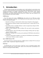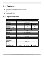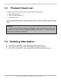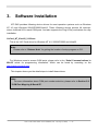
1
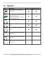
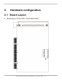
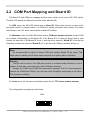
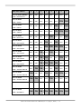
VXC Cards User’s Manual
For VXC-114U, VXC-144U/144iU
Warranty
All products manufactured by ICP DAS are warranted against
defective materials for a period of one year from the date of delivery to
the original purchaser.
Warning
ICP DAS assumes no liability for damages consequent to the use of
this product. ICP DAS reserves the right to change this manual at any
time without notice. The information furnished by ICP DAS is believed to
be accurate and reliable. However, ICP DAS assumes no responsibility
for its use, or for any infringements of patents or other rights of third
parties resulting from its use.
Copyright
Copyright 2007 by ICP DAS. All rights are reserved.
Trademark
The names used for identification only may be registered
trademarks of their respective companies.
VXC-114U/144U/144iU User’s Manual (Ver. 1.0, Sep.13, 2007) -----1
Tables of Contents
1.
2.
3.
4.
INTRODUCTION ..............................................................................................................................................................3
1.1
FEATURES ...........................................................................................................................................4
1.2
SPECIFICATIONS ..................................................................................................................................4
1.3
PRODUCT CHECK LIST .........................................................................................................................5
1.4
ORDERING INFORMATION .....................................................................................................................5
1.5
OPTIONS .............................................................................................................................................6
HARDWARE CONFIGURATION ..................................................................................................................................7
2.1
BOARD LAYOUT ...................................................................................................................................7
2.2
COM PORT MAPPING AND BOARD ID ...................................................................................................8
2.3
PIN ASSIGNMENT ...............................................................................................................................10
2.4
HARDWARE INSTALLATION ..................................................................................................................12
SOFTWARE INSTALLATION......................................................................................................................................13
3.1
WINDOWS NT 4.0 ..............................................................................................................................14
3.2
WINDOWS 2000 ................................................................................................................................17
3.3
WINDOWS XP/2003...........................................................................................................................21
3.4
WINDOWS VISTA ................................................................................................................................29
3.5
LINUX ................................................................................................................................................34
PROGRAMMING REFERENCE ..................................................................................................................................37
4.1
PCI HARDWARE IDS ..........................................................................................................................37
4.2
I/O ADDRESS MAPPING ......................................................................................................................37
4.3
UART REGISTER ...............................................................................................................................38
4.4
PROGRAMMABLE BAUD RATE .............................................................................................................39
VXC-114U/144U/144iU User’s Manual (Ver. 1.0, Sep.13, 2007) -----2
1. Introduction
The VXC series multi-port serial card enables user to install additional communication ports
on the PC. It’s the best choice for time-critical and reliably communications and controls on the
industrial environment. For example: communicates to PLC, FAB machine, meter, console
management of devices, laboratory instruments and Modem link, etc. In harsh industrial
environments, the onboard surge protection protects the computer and other equipment from
being damaged by high potential voltages.
COM-Selector:
The VXC series cards equip a COM-Selector (dip switch) for the COM port number
selection (automatically or manually). It’s an important and innovative feature of the VXC cards.
It has the following advantages:
• Simplifies the COM port number selection without using configuration utility programs.
• Users specify the COM port number exactly what they want, no matter which PCI slot
•
•
•
•
•
is using.
Automatically select an available COM port number is supported by setting the COMSelector (dip switch) to 0 (default).
Needn’t to install configuration utility for different OS, and needn’t to study operations
of the utility.
Prevents confusion. Other PnP COM port devices always confusing users by using a
dynamic COM port number.
Replacing an existing card is very easy, just by setting the COM-Selector (dip switches)
to the same.
It’s great for mass system installation, just setting the COM-Selector (dip switches) to
use the same COM port number in systems.
Up to 128KB Software FIFO:
The VXC card driver for Windows features a 128KB maximum software FIFO for each port
(default is 4KB). It’s practical for large file transmission.
Self-Tuner:
The RS-485 ports of VXC cards equip a “Self-Tuner” chip or equivalence design, which
controls the sending and receiving direction, baud rate and data format automatically and is
helpful for reducing the software loading.
VXC-114U/144U/144iU User’s Manual (Ver. 1.0, Sep.13, 2007) -----3
1.1 Features
z
z
z
z
Universal PCI V2.2, supports 5V and 3.3V PCI bus
COM-Selector
Provides surge protection
128-byte UART FIFO
1.2 Specifications
VXC-114U
VXC-144U
VXC-144iU
Universal PCI (5V and 3.3V)
Bus
Female DB-37
Connector
4 Ports
-
-
RS-422/485
-
4 Ports
4 Ports
Self-tuner or
equivalence design
-
Yes
Yes
Isolation
-
-
3KV
RS-232
COM-Selector
Yes
4 x 16C550 Compatible
UART
Baud rate
50 ~ 115200 bps
Data bits
5, 6, 7, 8
Parity Bit
None, Even, Odd, Mark, Space
Stop Bits
1, 1.5, 2
FIFO size
128 Bytes
Operating
Temperature
0 ~ 50 oC
Storage
Temperature
-20 to 70oC
0~90% non-condensing
Humidity
Dimensions (mm)
129 X83
129 X83
VXC-114U/144U/144iU User’s Manual (Ver. 1.0, Sep.13, 2007) -----4
129 X83
1.3
Product Check List
In addition to this manual, the package includes the following items:
• One VXC series card
• One ICP DAS software CD
• One release note
It is recommended that you read the release notes to see the software driver location
first.
Attention!
If any of these items are missing or damaged, contact the dealer from whom you
purchased the product. Save all shipping materials and the carton in case you need to
ship or store the product in the future.
1.4 Ordering Information
z
z
z
VXC-114U: Universal PCI, 4-port RS-232 Communication Board
VXC-144U: Universal PCI, 4-port RS-422/485 Communication Board
VXC-144iU: Universal PCI, 4-port Isolated RS-422/485 Communication Board
VXC-114U/144U/144iU User’s Manual (Ver. 1.0, Sep.13, 2007) -----5
1.5 Options
Item
Description
CA-4002
37-pin Male D-sub connector with
plastic cover
DN-37
CA-3710
VXC-114U
VXC-144U/144iU
3
3
3
3
3
3
3
3
3
3
9-pin Female D-sub & 5-wire RS-232
cable, 30cm
-
-
9-pin Female D-sub & 3-wire RS-232
cable, 1M
-
-
-
-
I/O Connector Block (Pitch= 5.08 mm)
with DIN-Rail Mounting
Include: One CA-3710 (37-pin MaleMale D-sub cable 1.0m)
37-Pin Male-Male D-sub cable 1M (45º)
CA-3710D
37-Pin Male-Male D-sub cable 1M
(180º)
CA-3720D
37-Pin Male-Male D-sub cable 2M
(180º)
CA-0903
CA-0910
CA-090910
9-pin Female D-sub & (9-wire) RS-422
Cable, 1M
VXC-114U/144U/144iU User’s Manual (Ver. 1.0, Sep.13, 2007) -----6
2.
Hardware configuration
2.1 Board Layout
z
Board layout of the VXC-114U/144U/144iU
VXC-114U/144U/144iU User’s Manual (Ver. 1.0, Sep.13, 2007) -----7
2.2 COM Port Mapping and Board ID
The Board ID and COM port mapping are the same, which is set by the SW1 DIP switch.
The SW1 DIP switch has different functions under different OS.
For DOS users, the SW1 DIP switch acts as Board ID. When there are two or more multiport serial cards in a single system, it is difficult to identify individual card number. For easier
identification, the VXC series card includes a Board ID function.
For Windows users, the SW1 DIP switch acts as COM port number selector and the COM
port number is depending on the Board ID. If the Board ID is 0, then the driver finds a valid
number for each port. If the Board ID is not 0, then the driver uses the “Board ID” to be the first
COM port number and uses the “Board ID +1” to be the next COM port number and so on.
Note:
It’s recommended to select a unique COM port number (Board ID) by users. This
helps users to identify and fix these cards and ports in a system without confuses.
Warning:
The port will not work if the COM port number is conflicted under Windows or Linux
system. In that case, users should try other COM port numbers.
Usually, the COM1 and COM2 are reserved by systems. And it’s recommended to
reserve the COM3 and COM4 if you will have other Plug&Play serial ports in the future.
This prevents confliction.
For Linux users, it’s the same as Windows users but for TTY device number selector.
The configuration examples are as follows.
SW1
VXC-114U/144U/144iU User’s Manual (Ver. 1.0, Sep.13, 2007) -----8
SW1 DIP Switch
Board ID=0x00 (Default)
8
7
6
5
4
3
2
1
OFF
OFF
OFF
OFF
OFF
OFF
OFF
OFF
OFF
OFF
OFF
OFF
OFF
OFF
ON
ON
OFF
OFF
OFF
OFF
OFF
ON
OFF
ON
OFF
OFF
OFF
OFF
OFF
ON
ON
ON
OFF
OFF
OFF
OFF
ON
OFF
OFF
ON
OFF
OFF
OFF
ON
OFF
ON
OFF
OFF
OFF
OFF
OFF
ON
ON
ON
ON
OFF
OFF
OFF
ON
OFF
ON
OFF
OFF
OFF
OFF
OFF
ON
ON
OFF
OFF
ON
OFF
OFF
OFF
ON
ON
ON
ON
OFF
OFF
OFF
ON
ON
OFF
OFF
ON
OFF
OFF
ON
OFF
OFF
ON
OFF
ON
ON
OFF
ON
ON
OFF
OFF
ON
OFF
OFF
OFF
ON
ON
ON
ON
ON
ON
ON
ON
COM = Auto-defined
Board ID=0x03
COM = 3/4/5/6
Board ID=0x05
COM = 5/6/7/8
Board ID=0x07
COM = 7/8/9/10
Board ID=0x09
COM = 9/10/11/12
Board ID=0x14
COM = 20/21/22/23
Board ID=0x1E
COM = 30/31/32/33
Board ID=0x28
COM = 40/41/42/43
Board ID=0x32
COM = 50/51/52/53
Board ID=0x3C
COM = 60/61/62/63
Board ID=0x64
COM = 100/101/102/103
Board ID=0x96
COM = 150/151/152/153
Board ID=0xC8
COM = 200/201/202/203
.
.
.
Board ID=0xFF
COM = 255/256/x/x
VXC-114U/144U/144iU User’s Manual (Ver. 1.0, Sep.13, 2007) -----9
2.3 Pin Assignment
2.3.1 VXC-114U Pin Assignment and Wiring
RS-232 Null Modem Cable Wiring
System 1
System 2
TX
RX
RX
TX
RTS
DCD
CTS
GND
GND
DSR
DTR
DCD
RTS
CTS
DTR
VXC-114U/144U/144iU User’s Manual (Ver. 1.0, Sep.13, 2007) -----10
DSR
2.3.2 VXC-144U/144iU Pin Assignment and Wiring
RS-485 Cable Wiring
System 1
System 2
DATA – (A)
DATA – (A)
DATA + (B)
DATA + (B)
RS-422 Cable Wiring
System 1
System 2
TxD-
RxD-
TxD+
RxD+
RxD+
TxD+
RxD-
TxD-
GND
GND
RTS-
CTS-
RTS+
CTS+
CTS+
RTS+
CTS-
RTS-
Warning:
The RS-485 bus is a differential (balanced) signal, thus you cannot wire the Data+
with Data- directly for a single port loop-back test. It will not work at all!
VXC-114U/144U/144iU User’s Manual (Ver. 1.0, Sep.13, 2007) -----11
2.4
Hardware Installation
Warning:
Static electricity can easily damage computer equipment. Ground yourself by touching
the chassis of the computer before touching any boards.
To install your VXC series cards, complete the following steps:
1.
2.
3.
4.
Refer to Chapter 3 for installing driver first
Turn off your computer
Remove all covers from the computer
Select an unused PCI slot
5.
6.
7.
8.
9.
Remove the PCI slot cover from the PC
Carefully insert your VXC card into the PCI slot
Attach the cable to the connector
Replace the PC cover
Power on the computer
Note:
It’s recommended to install driver first, since some OS (operating system such as
Windows 2000) may ask you to restart the computer again after driver installation. This
reduces the times to restart the computer.
VXC-114U/144U/144iU User’s Manual (Ver. 1.0, Sep.13, 2007) -----12
3.
Software Installation
ICP DAS provides following device drivers for most operation systems such as Windows
NT 4.0 and Windows 2000/XP/2003/Vista32. These Windows drivers provide full interruptdriven, buffered I/O for each COM ports. And also supports the Plug & Play mechanism for easy
installation.
VxCard_NT_Vista32_V102.exe:
This is the VXC Card driver for Windows NT 4.0, 2000/XP/2003 and Vista32.
Note:
Please refer to “Release Note” for getting the location of setup program on CD.
For Windows users to access COM ports, please refer to the “Serial Communications in
Win32” article for programming information. Which can be found by searching on the
http://msdn.microsoft.com.
This chapter shows you the detail steps to install these drivers.
Note:
For more information about COM port number selection, please refer to Section 2.2
“COM Port Mapping & Board ID”.
VXC-114U/144U/144iU User’s Manual (Ver. 1.0, Sep.13, 2007) -----13
3.1 Windows NT 4.0
3.1.1 Installation
Note:
It’s recommended to install the software first, and then the hardware. This reduces the
configuration procedures.
Refer to “Release Note” for getting the location of setup program on CD.
1. Launch the “VxCard_NT_Vista32_v102.exe” setup program.
2. Click the “Next >” button to start installation.
3. Select a folder where setup will install files, and click “Next>” button.
VXC-114U/144U/144iU User’s Manual (Ver. 1.0, Sep.13, 2007) -----14
4. Check “Create a desktop icon” and click “Next>” button.
5. Select “No, I will restart the computer later” and click “Finish” button.
VXC-114U/144U/144iU User’s Manual (Ver. 1.0, Sep.13, 2007) -----15
6. Turn off the computer and install the VXC card into the PC.
7. Power on the computer.
3.1.2 Verification
ICP DAS provides a ”VxCard Utility” program (VxCardUtil.exe) for users to see all the COM
ports on the system. It shows COM ports in two gorups, one for VXC Card and one for others.
So, users can check if any confliction occurred between COM ports.
To launch the utility, just double-click on the ”VxCard Utility” short-cut on your desktop.
3.1.3 Configuration
If need, users can change the input buffer size (default is 4KB for each port, up to 128KB) by
setting the “SW FIFO” scroll-bar on the VxCard Utility.
To change the COM port mappings (see Section 2.2 COM Port Mappings and Board ID),
users should restart the driver by rebooting the computer.
VXC-114U/144U/144iU User’s Manual (Ver. 1.0, Sep.13, 2007) -----16
3.2 Windows 2000
3.2.1 Installation
Note:
It’s recommended to install the software first, and then the hardware. This reduces the
configuration procedures.
Refer to “Release Note” for getting the location of setup program on CD.
1. Launch the VxCard_NT_Vista32_V102.exe to install the driver and register the related
information onto the system.
2. Click “Next>” button to start installation.
3. Select a folder where setup will install files, and click “Next>” button.
VXC-114U/144U/144iU User’s Manual (Ver. 1.0, Sep.13, 2007) -----17
4. Check “Create a desktop icon” and click “Next>” button.
5. Select “No, I will restart the computer later” and click “Finish” button.
VXC-114U/144U/144iU User’s Manual (Ver. 1.0, Sep.13, 2007) -----18
6. Turn off the computer and install the VXC card into the PC.
7. Power on the computer, Windows 2000 should find the new card and load the driver
automatically. (Sometimes Win2K pops up few confirm dialog box, just click “next” or “OK” to
finish it.)
3.2.2 Verification
To verify the installation, please complete the following steps:
1.
2.
Select ”Start / Settings / Control Panel” and double-click the ”System” icon.
Click the ”Hardware” tab and then click the ”Device Manager” button.
The VXC Card is listed under the ”VXC Multi-port serial Card” class, and each
Communications Port is listed under the ”Ports (VxCard – RS-232/422/485)” class.
VXC-114U/144U/144iU User’s Manual (Ver. 1.0, Sep.13, 2007) -----19
3.2.3
Configuration
If need, users can change the input buffer size (default is 4KB for each port, up to 128KB) by
setting the “SW FIFO” scroll-bar on the VxCard Utility. The utility’s short cut is placed on the
desktop after installation.
To change the COM port mappings (see Section 2.2 COM Port Mappings and Board ID),
users should restart the driver by rebooting the computer, or re-install the “VXC Card” hardware
in the “Device Manager” by un-install card and then scan new hardware.
3.2.4 Uninstallation
Before removing the card from your computer, it’s recommended to uninstall the device from
the ”Device Manager”. This removes unused hardware information from the database (registry)
of Windows.
VXC-114U/144U/144iU User’s Manual (Ver. 1.0, Sep.13, 2007) -----20
3.3
Windows XP/2003
It’s recommend to disable the Driver Signing and Windows Update options in Windows to
suppress the lots of prompt messages during driver installation.
3.3.1 Disable Driver Signing
1. Select ”Start / Settings / Control Panel” and then ”System”.
2. Select the “Hardware” page on “System Properties” window and click the “Driver
Signing” button.
VXC-114U/144U/144iU User’s Manual (Ver. 1.0, Sep.13, 2007) -----21
3. Select “Ignore – Install the software anyway and don’t ask for my approval”,
check “Make this action the system default” and then
click “OK” to close the “Driver Signing Options” window.
4. Click the “Windows Update” button on “System Properties” window.
Note:
The “Windows Update”
setting supports Windows
XP SP2 only. If the system
is not Windows XP SP2,
please skip step 4 to 6.
VXC-114U/144U/144iU User’s Manual (Ver. 1.0, Sep.13, 2007) -----22
5. Select “Never search Windows Update for drivers” and click “OK”.
6. Click “OK” on “System Properties” window to close it.
3.3.2 Driver Installation
Note:
It’s recommended to install the software first, and then the hardware. This reduces
the configuration procedures.
Refer to “Release Note” for getting the location of setup program on CD.
1. Launch the VxCard_NT_Vista32_V102.exe to install the driver and register the related
information onto the system.
2. Click “Next>” button to start installation.
VXC-114U/144U/144iU User’s Manual (Ver. 1.0, Sep.13, 2007) -----23
3. Select a folder where setup will install files, and click “Next>” button.
4. Check “Create a desktop icon” and click “Next>” button.
VXC-114U/144U/144iU User’s Manual (Ver. 1.0, Sep.13, 2007) -----24
5. Select “No, I will restart the computer later” and click “Finish” button.
6. Turn off the computer and install the VXC card into the PC.
7. Power on the computer and continue to finish the Plug and Play procedures.
8. Select “Install the software automatically [Recommended]” and Click “Next>” button.
VXC-114U: 4-Port RS-232 Communication Board
VXC-114U/144U/144iU User’s Manual (Ver. 1.0, Sep.13, 2007) -----25
9. Click “Finish” button.
10. Windows pops up “Found New Hardware Wizard” dialog box again. Please repeat the step
8 to 9 to finish the installation for all COM ports.
3.3.3 Restore the Driver Signing Setting
1. Select ”Start / Settings / Control Panel” and then ”System”.
2. Select the “Hardware” page on “System Properties” window and click “Driver Signing”.
3. Select “Warn – Prompt me each time to choose an action”,
check “Make this action the system default” and then
click “OK” to close the “Driver Signing Options” window.
4. Click the “Windows Update” button on “System Properties” window.
Note:
The “Windows Update” setting supports Windows XP SP2 only. If the system is
not Windows XP SP2, please skip step 4 to 6.
VXC-114U/144U/144iU User’s Manual (Ver. 1.0, Sep.13, 2007) -----26
5. Select “Ask me to search Windows Update every time I connect a new device” and click
“OK” button.
6. Click “OK” button to close the “System Properties” window.
3.3.4 Verification
To verify the installation, please complete the following steps:
1. Select ”Start / Settings / Control Panel” and double-click the ”System” icon.
2. Click the ”Hardware” tab and then click the ”Device Manager” button.
The VXC Card is listed under the ”VXC Multi-port serial Card” class, and each
Communications Port is listed under the ”Ports (VxCard – RS-232/422/485)” class.
VXC-114U/144U/144iU User’s Manual (Ver. 1.0, Sep.13, 2007) -----27
3.3.5 Configuration
If need, users can change the input buffer size (default is 4KB for each port, up to 128KB) by
setting the “SW FIFO” scroll-bar on the VxCard Utility. The utility’s short cut is placed on the
desktop after driver installed.
To change the COM port mappings (see Section 2.2 COM Port Mappings and Board ID),
users should restart the driver by rebooting the computer, or re-install the “VXC Card” hardware
in the “Device Manager” by un-install card and then scan new hardware.
3.3.6 Uninstallation
Before removing the card from your computer, it’s recommended to uninstall the device from
the ”Device Manager”. This removes unused hardware information from the database (registry)
of Windows.
VXC-114U/144U/144iU User’s Manual (Ver. 1.0, Sep.13, 2007) -----28
3.4
Windows Vista
3.4.1 Driver Installation
Note:
It’s recommended to install the software first, and then the hardware. This reduces
the configuration procedures.
Refer to “Release Note” for getting the location of setup program on CD.
1. Launch the VxCard_NT_Vista32_V102.exe to install the driver and register the related
information onto the system.
2. Click “Allow, I trust this program. I know where it’s from or I’ve used it before” on the
“User Account Control” window.
3. Click “Next>” button to start installation.
VXC-114U/144U/144iU User’s Manual (Ver. 1.0, Sep.13, 2007) -----29
4. Select folder where setup will install files, and click “Next>” button.
5. Check “Create a desktop icon” and click “Next>” button.
VXC-114U/144U/144iU User’s Manual (Ver. 1.0, Sep.13, 2007) -----30
6. Click “Install this driver software anyway”.
Note:
The prompt will repeat
for several times. Please
click “(Install this driver
software anyway)” for all
these prompts.
7. Select “No, I will restart the computer later” and click “Finish” button.
8. Turn off the computer and install the VXC card into the PC.
9. Power on the computer and system will find the new card and make it work automatically.
VXC-114U/144U/144iU User’s Manual (Ver. 1.0, Sep.13, 2007) -----31
3.4.2 Verification
To verify the installation, please complete the following steps:
1. Select ”Start / Settings / Control Panel” and double-click the ”System” icon.
2. Click the ”Hardware” tab and then click the ”Device Manager” button.
The VXC Card is listed under the ”VXC Multi-port serial Card” class, and each
Communications Port is listed under the ”Ports (VxCard – RS-232/422/485)” class.
3.4.3 Configuration
If need, users can change the input buffer size (default is 4KB for each port, up to 128KB) by
setting the “SW FIFO” scroll-bar on the VxCard Utility. The utility’s short cut is placed on the
desktop after driver installed.
VXC-114U/144U/144iU User’s Manual (Ver. 1.0, Sep.13, 2007) -----32
1. Right–click “VxCard Utility.exe” and select “Run as administrator”.
2. Click “Allow, I trust this program. I know where it’s from or I’ve used it before” on the
“User Account Control” window.
3. The VXC Card Utility shows all COM ports that existing in the system.
To change the COM port mappings (see Section 2.2 COM Port Mappings and Board ID),
users should restart the driver by rebooting the computer, or re-install the “VXC Card” hardware
in the “Device Manager” by un-install card and then scan new hardware.
3.4.4 Uninstallation
Before removing the card from your computer, it’s recommended to uninstall the device from
the ”Device Manager”. This removes unused hardware information from the database (registry)
of Windows.
VXC-114U/144U/144iU User’s Manual (Ver. 1.0, Sep.13, 2007) -----33
3.5 Linux
This section describes VXC Card Linux driver’s features and how to compile and install into
a general Linux system(linux kernel 2.4.X or 2.6.X). The VXC Card Linux driver is modified from
Linux kernel source and supports most of popular PC-based Linux distributions.
3.5.1 Driver Features
z
z
z
z
Device file.
Dynamic device allocation.
Dynamic major number.
One major number for multiple devices.
z
Use the GNU configure and build system.
3.5.2 Installation
Please refer to the following steps to complete it.
1. Download or copy the IxCOM package to a directory that you have access to.
2. Extract the package. For example, the package's file name is "ixcom-0.8.1.tar.gz" and its
path related to your current working directory is../pkg, then the extraction command would
be
#tar -zxvf ../pkg/ixcom-0.8.1.tar.gz
An ixcom-0.8.1 directory is created after extraction.
3. For convenient access, it is a good idea to put a symbol-link on it.
#ln -s ixcom-0.8.1 ixcom
4. Change to the ixcom working directory you just made, type
#./configure to create proper Makefiles.
VXC-114U/144U/144iU User’s Manual (Ver. 1.0, Sep.13, 2007) -----34
5. Once the configuring has done successfully, type “make” to build all.
Note: If you like to install files to system directory, the make install will do it for you. However,
install files to system directory is not necessary for further operation. You will need the root
privilege for that.
Script “./ixcom.inst” loads modules automatically. Script “./ixcom.remove” removes the
loaded modules. The root privilege is required when installing or removing these kernel modules.
3.5.3 Access To VXC Serial Port
Script “ixcom.inst” will establish unused device major number dynamically and create
correspond device node for access VXC serial port.
# ./ixcom.inst
IxCOM Installer 0.5.0
Check kernel version... 2.6
Use proc-file /proc/icpdas/ixcom
Load module ixcom
Use “dmesg” command to inspect the driver output message.
dmesg
………
………
ICPDAS VXC multi-serial card Serial driver version ixcom-0.8.1 (2007-08-21)
Found ICPDAS VXC-114U series board(BusNo=0,DevNo=20)
PCI: Found IRQ 11 for device 0000:00:14.0
PCI: Sharing IRQ 11 with 0000:00:07.2
PCI: Sharing IRQ 11 with 0000:00:14.1
ttySV0 at port cc00 (irq = 11) is a 16C950/954
ttySV1 at port d000 (irq = 11) is a 16C950/954
ttySV2 at port d400 (irq = 11) is a 16C950/954
ttySV3 at port d800 (irq = 11) is a 16C950/954
VXC-114U/144U/144iU User’s Manual (Ver. 1.0, Sep.13, 2007) -----35
The script “ixcom.inst” had loaded module into kernel and find a VXC card that have four
serial port, ttySV0, ttySV1, ttySV2 and ttySV3.
The “ixcom.inst” script will use major number 254 to create correspond device on the /dev.
# ls -la /dev/ttySV?
crw-rw-rw- 1 root
crw-rw-rw- 1 root
crw-rw-rw- 1 root
crw-rw-rw- 1 root
crw-rw-rw- 1 root
crw-rw-rw- 1 root
crw-rw-rw- 1 root
crw-rw-rw- 1 root
crw-rw-rwcrw-rw-rw-
root
root
root
root
root
root
root
root
254,
254,
254,
254,
254,
254,
254,
254,
64 Jul 14 10:13 /dev/ttySV0
65 Jul 14 10:13 /dev/ttySV1
66 Jul 14 10:13 /dev/ttySV2
67 Jul 14 10:13 /dev/ttySV3
68 Jul 14 10:13 /dev/ttySV4
69 Jul 14 10:13 /dev/ttySV5
70 Jul 14 10:13 /dev/ttySV6
71 Jul 14 10:13 /dev/ttySV7
1 root root 254, 72 Jul 14 10:13 /dev/ttySV8
1 root root 254, 73 Jul 14 10:13 /dev/ttySV9
To remove VXC driver from system use script “./ixcom.remove” to removes the loaded
modules.
VXC-114U/144U/144iU User’s Manual (Ver. 1.0, Sep.13, 2007) -----36
4. Programming Reference
4.1 PCI Hardware IDs
Card
Vendor ID
Device ID
Sub-Vendor ID
Sub-Device ID
VXC-114U
0x1415
0x9504
0x1441
0x0090
Extension for
VXC-114U
0x1415
0x9511
0x1441
0x0000
VXC-144U
VXC-144iU
0x1415
0x9504
0x1440
0x0090
Extension for
VXC-144U/144iU
0x1415
0x9511
0x1440
0x0000
4.2 I/O Address Mapping
The I/O address of the VXC series card is automatically assigned by the main-board ROM
BIOS. The VXC-114U and VXC-144U/144iU cards using two PCI functions as followings:
Function 0
Function 1
BAR0
UART0 (I/O Mapped)
Local Bus (I/O Mapped)
BAR1
UART1 (I/O Mapped)
Local Bus (Memory Mapped)
BAR2
UART2 (I/O Mapped)
Reserved
BAR3
UART3 (I/O Mapped)
Reserved
BAR4
Local Configuration Registers
(I/O Mapped)
Reserved
BAR5
UARTs / Local Configuration
Registers (Memory Mapped)
Reserved
Base Address
Register
Note: Please contact us for more information about I/O Address Mapping.
VXC-114U/144U/144iU User’s Manual (Ver. 1.0, Sep.13, 2007) -----37
4.3 UART Register
VXC-114U/144U/144iU User’s Manual (Ver. 1.0, Sep.13, 2007) -----38
4.4 Programmable Baud Rate
Baud Rates Using a 14.7456-MHz Crystal (VXC-114U, VXC-144U/144iU)
DESIRED
BAUD RATE
DIVISOR USED TO
GENERATE 16× CLOCK
50
18432
75
12288
110
8376
150
6144
300
3072
600
1536
1200
768
2400
384
4800
192
9600
96
14400
64
19200
48
23040
40
28800
32
38400
24
56000
16
57600
16
115200
8
184320
5
230400
4
307200
3
460800
2
PERCENT (%) ERROR
0.026
2.86
Warning: The baud rates higher than 115,200 bps are not guaranteed to work.
VXC-114U/144U/144iU User’s Manual (Ver. 1.0, Sep.13, 2007) -----39
To generate baud rate 125,000 bps:
125,000 * 16 * 8 = 16,000,000 = 16MHz crystal
So, when you use a 16MHz crystal and selecting the baud rate 115,200 bps in your software
setting, the hardware will generate baud rate 125kbps actually.
Warning: The baud rates higher than 115,200 bps are not guaranteed to work.
To generate baud rate 250,000 bps:
250,000 * 16 * 4 = 16,000,000 = 16MHz crystal
(Baud rate * 16x clock * Divisor = Crystal Clock Frequency)
Thus, when you use a 16MHz crystal and selecting the baud rate 230,400 bps in your
software setting, the hardware will generate baud rate 250kbps actually.
Note: The multi-port serial cards can have a special baud rate in OEM version. Please
contact us for more information regarding the OEM products.
VXC-114U/144U/144iU User’s Manual (Ver. 1.0, Sep.13, 2007) -----40