1
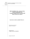
Preliminary DM8000 Series 1550 nm Direct Modulation Transmitter User Manual For more information on this and other products: Contact Sales at EMCORE 626-293-3400, or visit www.emcore.com. DM8000 Series 1550nm Direct Modulation Transmitter PRELIMINARY USER MANUAL | MAY 03, 2011 Table of Contents Table of Contents.................................................................................................................................. 2 Safety Information ................................................................................................................................. 4 Power Requirements ..................................................................................................................... 4 Safety Instructions ......................................................................................................................... 4 Before Initializing and Operating the Unit ....................................................................................... 4 Safety Symbols.............................................................................................................................. 4 Getting Started ...................................................................................................................................... 5 Before Initializing and Operating the Unit ....................................................................................... 5 Note: Keep the packaging. ............................................................................................................. 5 Operating Environment .................................................................................................................. 5 Humidity ........................................................................................................................................ 6 Transmitter Dimensions ................................................................................................................. 8 Transmitter Dimensions ................................................................................................................. 9 Optical and RF Characteristics............................................................................................................ 11 Optical Connections..................................................................................................................... 11 Transmitter Controls and Indicators .................................................................................................... 14 Front Panel .................................................................................................................................. 14 Rear Panel................................................................................................................................... 14 User Interface .............................................................................................................................. 15 VFD: Front Panel Menus and Operation ...................................................................................... 15 Show Parameters ........................................................................................................................ 15 Show Alarms................................................................................................................................ 17 Remote Monitoring: SNMP .......................................................................................................... 18 General Background of SNMP ..................................................................................................... 18 SNMP .......................................................................................................................................... 18 Configuring the Transmitter for Network Communication ............................................................. 18 Connecting to the RS-232 interface ............................................................................................. 19 Setting the real-time clock ............................................................................................................ 22 Setting the IP address of the transmitter ...................................................................................... 23 Configuring the SNMP agent ....................................................................................................... 25 Power supply configuration .......................................................................................................... 26 Establish updated network connection ......................................................................................... 27 Network configuration .................................................................................................................. 28 Telnet service .............................................................................................................................. 29 MIBs ............................................................................................................................................ 30 Unit Alarms (enabled through unitStatusEnable OID bits) ............................................................ 31 Miscellaneous Alarms (enabled through miscStatusEnable OID bits) .......................................... 31 SCTE MIB support ....................................................................................................................... 31 SNMPv2 Traps ............................................................................................................................ 32 Transmitter Basic Principle of Operation ............................................................................................. 33 Transmitter signal flow ................................................................................................................. 33 Transmitter and EDFA System Deployment ........................................................................................ 34 Choosing the Correct Transmitter and EDFA for a System .......................................................... 34 Applicable Standards Compliance ...................................................................................................... 36 EMI/EMC ..................................................................................................................................... 36 Safety .......................................................................................................................................... 36 Handling / Packaging .......................................................................................................................... 36 EMCORE Corporation 2015 West Chestnut Street Alhambra, California 91803-1542 Tel: 626-293-3400 Fax: 626-293-3428 www.emcore.com Copyright © 2011. EMCORE Corporation Page 2 of 38 DM8000 Series 1550nm Direct Modulation Transmitter PRELIMINARY USER MANUAL | MAY 03, 2011 Packaging .................................................................................................................................... 36 Handling ...................................................................................................................................... 36 Model Number Information.................................................................................................................. 37 EMCORE Corporation 2015 West Chestnut Street Alhambra, California 91803-1542 Tel: 626-293-3400 Fax: 626-293-3428 www.emcore.com Copyright © 2011. EMCORE Corporation Page 3 of 38 DM8000 Series 1550nm Direct Modulation Transmitter PRELIMINARY USER MANUAL | MAY 03, 2011 Safety Information Power Requirements The system can operate from an AC power source that supplies 100 V AC to 240 V AC 47-63 Hz or a DC power source that supplies 36 to 72 V DC. Safety Instructions The following safety instructions must be observed whenever the unit is operated, serviced, or repaired. Failure to comply with any of these instructions or with any precaution or warning contained in the user’s manual is in direct violation of the standards of design, manufacture, and intended use of the unit. Emcore assumes no liability for the customer’s failure to comply with any of these safety requirements. Before Initializing and Operating the Unit Inspect the unit for any signs of damage, and read the user’s manual thoroughly. Install the unit as specified in the Getting Started section. Ensure that the unit and any devices or cords connected to it are properly grounded. Safety Symbols The following symbols and messages can be marked on the unit (Table 1). Observe all safety instructions that are associated with a symbol. Table 1: Safety Symbols Symbol Description Laser safety. See the user’s manual for instructions on handling and operating the unit safely. See the user’s manual for instructions on handling and operating the unit safely. Electrostatic discharge (ESD). See the user’s manual for instructions on handling and operating the unit safely. Frame or chassis terminal for electrical grounding within the unit. Protective conductor terminal for electrical grounding to the earth. EMCORE Corporation 2015 West Chestnut Street Alhambra, California 91803-1542 Tel: 626-293-3400 Fax: 626-293-3428 www.emcore.com Copyright © 2011. EMCORE Corporation Page 4 of 38 DM8000 Series 1550nm Direct Modulation Transmitter WARNING CAUTION PRELIMINARY USER MANUAL | MAY 03, 2011 The procedure can result in serious injury or loss of life if not carried out in proper compliance with all safety instructions. Ensure that all conditions necessary for safe handling and operation are met before proceeding. The procedure can result in serious damage to or destruction of the unit if not carried out in compliance with all instructions for proper use. Ensure that all conditions necessary for safe handling and operation are met before proceeding. Getting Started Before Initializing and Operating the Unit 1. 2. 3. 4. Inspect the transmitter for any signs of damage, and read the User’s Manual thoroughly. Install the transmitter as specified in the Getting Started section. Ensure that the transmitter and any devices or cords connected to it are properly grounded. Become familiar with all safety symbols and instructions to ensure that the transmitter is operated and maintained safely. Initial Inspection WARNING WARNING: To avoid electrical shock, do not initialize or operate the unit if it bears any sign of damage to any portion of its exterior surface, such as the outer cover or panels. Check that the unit and contents are complete: 1. Wear an anti-static wrist strap and work in an electrostatic discharge (ESD) controlled area. 2. Inspect the shipping container for any indication of excessive shock to the contents, and inspect the contents to ensure that the shipment is complete. 3. Inspect the unit for structural damage that can have occurred during shipping. Note: Keep the packaging. Immediately inform Emcore and, if necessary, the carrier if the contents of the shipment are incomplete, if the unit or any of its components are damaged or defective, or if the unit does not pass the initial inspection. Operating Environment In order for the unit to meet the warranted specifications, the operating environment must meet the following conditions for temperature and humidity. EMCORE Corporation 2015 West Chestnut Street Alhambra, California 91803-1542 Tel: 626-293-3400 Fax: 626-293-3428 www.emcore.com Copyright © 2011. EMCORE Corporation Page 5 of 38 DM8000 Series 1550nm Direct Modulation Transmitter PRELIMINARY USER MANUAL | MAY 03, 2011 Temperature The unit can be operated in the temperature range of 0 to 50°C (standard). Humidity The transmitter can be operated in environments with up to 85% humidity, non-condensing (0°C to 50 °C). Do not expose it to any environmental conditions or changes to environmental conditions that can cause condensation to form inside the transmitter. WARNING • WARNING: Do not use the unit outdoors. • WARNING: To prevent potential fire or shock hazard, do not expose the unit to any source of excessive moisture. Storing and Shipping To maintain optimum operating reliability, do not store the unit in locations where the temperature falls below -40°C or rises above 85°C. Avoid any environmental condition that can result in internal condensation. Ensure that these temperature and humidity requirements can also be met whenever the unit is shipped. Claims and Repackaging Immediately inform Emcore and, if necessary, the carrier, if •The contents of the shipment are incomplete •The unit or any of its components are damaged or defective •The unit does not pass the initial inspection In the event of carrier responsibility, Emcore will allow for the repair or replacement of the unit while a claim against the carrier is being processed. Returning Shipments to Emcore Emcore will only accept returns for which an approved Return Material Authorization (RMA) has been issued. This number must be obtained prior to shipping any material to Emcore. The owner’s name and address, the model number and full serial number of the unit, the RMA number, and an itemized statement of claimed defects must be included with the return material. Ship the return material in the original shipping container and packing material. If these are not available, typical packaging guidelines are as follows: EMCORE Corporation 2015 West Chestnut Street Alhambra, California 91803-1542 Tel: 626-293-3400 Fax: 626-293-3428 www.emcore.com Copyright © 2011. EMCORE Corporation Page 6 of 38 DM8000 Series 1550nm Direct Modulation Transmitter PRELIMINARY USER MANUAL | MAY 03, 2011 1. Wear an anti-static wrist strap and work in an ESD controlled area. 2. Wrap the unit in anti-static packaging. Use anti-static connector covers, as applicable. 3. Pack the unit in a reliable shipping container. 4. Use enough shock-absorbing material (10 to 15 cm or 4 to 6 in on all sides) to cushion the unit and prevent it from moving inside the container. Pink poly anti-static foam is recommended. 5. Seal the shipping container securely. 6. Clearly mark FRAGILE on its surface. 7. Always provide the model and serial number of the unit and, if necessary, the RMA number on any accompanying documentation. 8. Please contact the RMA department, using the contact information at the beginning of this document, to provide an RMA number and a shipping address. Unpacking 1. Inspect the shipping boxes for any obvious damage. 2. Unpack the unit from all packaging boxes. 3. Inspect the appearance of the unit for any shipping damage. 4. In case of damage, document and inform the shipping company and your local representative. 5. Save the shipping boxes and their inserts for any future reshipment for upgrade or repair. NOTE: In the event of a reshipment back to the manufacturer, any additional damage caused by not using the original boxes will be considered the responsibility of the customer. Transmitter Mounting and Power Connection 1. Mount the unit into a 19-inch wide rack or cabinet (or 23-inch with optional mounting kit). 2. Turn the unit power supply switch(es) located on the rear panel off. 3. Turn the key switch located on the front panel to the OFF position. 4. For dual AC powered models: Plug the two power cords supplied with the transmitter into the three-prong connectors on the rear panel of the transmitter and plug the other ends of the two power cords into a 100-240 VAC, 47-63 Hz power source (e.g. wall socket). 5. For DC powered models: Connect wires DC+, DC-, and GND to the pluggable terminal block that is connected to the DC input of the power supply. The DC power source must be 36 – 72VDC and wires used must handle 65VA. 6. Turn the unit power switch to the ON position. Note:The transmitter can operate with a single power supply and/or from two different power sources. CAUTION: DOUBLE POLE/NEUTRAL FUSING EMCORE Corporation 2015 West Chestnut Street Alhambra, California 91803-1542 Tel: 626-293-3400 Fax: 626-293-3428 www.emcore.com Copyright © 2011. EMCORE Corporation Page 7 of 38 DM8000 Series 1550nm Direct Modulation Transmitter PRELIMINARY USER MANUAL | MAY 03, 2011 Earth grounding of AC supplies in Scandinavian countries. Finland: "Laite on liitettävä suojamaadoituskoskettimilla varustettuun pistorasiaan " Norway : “Apparatet må tilkoples jordet stikkontakt” Sweden: "Apparaten skall anslutas till jordat uttag." Laser Safety Label EMCORE Corporation 2015 West Chestnut Street Alhambra, California 91803-1542 Tel: 626-293-3400 Fax: 626-293-3428 www.emcore.com Copyright © 2011. EMCORE Corporation Page 8 of 38 DM8000 Series 1550nm Direct Modulation Transmitter PRELIMINARY USER MANUAL | MAY 03, 2011 Transmitter Dimensions EMCORE Corporation 2015 West Chestnut Street Alhambra, California 91803-1542 Tel: 626-293-3400 Fax: 626-293-3428 www.emcore.com Copyright © 2011. EMCORE Corporation Page 9 of 38 DM8000 Series 1550nm Direct Modulation Transmitter PRELIMINARY USER MANUAL | MAY 03, 2011 Operating the Transmitter WARNING To avoid the risk of injury or death, always observe the following precautions before initializing the transmitter. If using a voltage-reducing autotransformer to power the transmitter, ensure that the common terminal connects to the earthed pole of the power source. Use only the type of power cord supplied with the transmitter. Connect the power cord only to a power electrical outlet equipped with a protective earth contact. Never connect to an extension cord that is not equipped with this feature. Willfully interrupting the protective earth connection is prohibited. Never look into the end of an optical cable connected to an optical output device that is operating. Laser radiation is invisible, and direct exposure can severely injure the human eye. For more information, see the User’s Manual of the laser source in use. Turning off the power to the laser component does not always block the externally supplied radiation to the connector at the output of the transmitter. Do not use the transmitter outdoors. To prevent potential fire or shock hazard, do not expose the transmitter to any source of excessive moisture. Do not operate the transmitter when its covers or panels have been removed. Do not interrupt the protective earth grounding. Any such action can lead to a potential shock hazard that can result in serious personal injury. Do not operate the transmitter if an interruption to the protective grounding is suspected. In this case, ensure that the transmitter remains inoperative. Use only the type of fuse specified by the manufacturer as appropriate for this transmitter. Do not use repaired fuses, and avoid any situations that can short-circuit the fuse. Unless absolutely necessary, do not attempt to adjust or perform any maintenance or repair procedure when the unit is opened and connected to a power source. Repairs are to be carried out only by a qualified professional. Do not attempt any adjustment, maintenance, or repair procedure to the transmitter’s internal mechanism if immediate first aid is not accessible. Disconnect the power cord from the unit before adding or removing any components. Operating the unit in the presence of flammable gases or fumes is extremely hazardous. Do not perform any operating or maintenance procedure that is not described in the User’s Manual. Some of the transmitter’s capacitors can be charged even when the unit is not connected to the power source. EMCORE Corporation 2015 West Chestnut Street Alhambra, California 91803-1542 Tel: 626-293-3400 Fax: 626-293-3428 www.emcore.com Copyright © 2011. EMCORE Corporation Page 10 of 38 DM8000 Series 1550nm Direct Modulation Transmitter PRELIMINARY USER MANUAL | MAY 03, 2011 Optical and RF Characteristics Optical Characteristics Number of Optical Outputs Optical Output Connector Type One (1): DM8000-U-vvv-www-xxx-yy-110/107-aa-pp Two (2): DM8000-U-vvv-www-xxx-yy-207-aa-pp SC/APC Bulkhead (standard) (FC/APC and E2000 to be provided as option) Optical fibers for connectors shall be retained internally to allow user removal of optical bulkhead connector for cleaning. Optical Connector Location Front or Rear panel mounted Optical Connections 1. Clean all fiber patch cords before connecting to the transmitter. Cleaning Guidelines: Fiber Patch cord connectors - Remove the fiber connectors dust cap and wipe the fiber connector tip with a dry lint-free cloth (such as Kimwipes). Inspect for scratches or debris on connector surface by using a microscopes (ie.100x or 200x). - If no scratches or debris are found the connector is now clean and ready for connection. If debris or scratches are found then repeat the fiber patch cord connector cleaning guidelines. Fiber Bulkhead connectors - Compressed air may be used to clean fiber bulkhead connectors. Use compressed air with at least the following specifications: - Non-residue, inert gas for precision dust removal - Ultra-filtered to < 0.2 microns - Recommended for optical systems. - Using compressed air as listed above, remove the bulkhead dust cover and hold the can of compressed air about 6 inches from the connector. After spraying a few short bursts into the bulkhead the connector is clean and ready for connection. - If compressed air is not available, the transmitter fiber bulkhead connector may be cleaned by 2.5 mm cotton swap or connector plate may be removed to clean the internal fiber patch cords. CAUTION CAUTION: Use caution when handling fibers. Do not exceed fiber manufacturers pulling tension or bend radius specifications when removing fiber bulkhead connector plate. - To remove the transmitter optical connector plate, remove the screw on the far left of the optical plate and remove the screw on the far right of the optical plate. Do not remove the screws on the optical bulkhead connector. - Slowly remove the optical connector plate from the rear panel and disconnect each fiber connector from the bulkhead mounted on the plate. - Clean each fiber connector according to section A of the fiber cleaning guidelines. EMCORE Corporation 2015 West Chestnut Street Alhambra, California 91803-1542 Tel: 626-293-3400 Fax: 626-293-3428 www.emcore.com Copyright © 2011. EMCORE Corporation Page 11 of 38 DM8000 Series 1550nm Direct Modulation Transmitter 2. 3. 4. 5. 6. PRELIMINARY USER MANUAL | MAY 03, 2011 Make sure the laser key switches on the front panel of the transmitter are in the OFF position. Connect a fiber patch cord from the output of the transmitter to an optical power meter. Turn the transmitter laser key switch to the ON position. Using the optical power meter verify the transmitter optical power is within specification. Turn the transmitter laser key switch to the OFF position. RF Characteristics Number of RF Inputs RF Input Connector Type RF Test Point Connector Type One (1): DM8000-U-vvv-www-C75-yy-zzz-aa-pp Two (2): DM8000-U-vvv-www-L75-yy-zzz-aa-pp Female ‘F’ type: D-Hole Connector Front or Rear Mounted Female ‘F’ type: D-Hole Connector Front or Rear Mounted Analog Connection to DM8000: Analog Channels Analog and QAM Connection to DM8000: Analog Channels Combiner QAM Channels EMCORE Corporation 2015 West Chestnut Street Alhambra, California 91803-1542 Tel: 626-293-3400 Fax: 626-293-3428 www.emcore.com Copyright © 2011. EMCORE Corporation Page 12 of 38 DM8000 Series 1550nm Direct Modulation Transmitter PRELIMINARY USER MANUAL | MAY 03, 2011 Set each channel to the correct RF level as shown in the below table and connect the RF (CATV) channels to the F connector labeled “CATV IN”. RF Level/ch Composite (dBmV) (dBm) 15 -14.77 79ch = 15 75ch QAM = 9 (Level after combiner) -13.84 (Level after combiner) 17.75 -14.77 16.2 -14.77 JCTEA: 57ch Analog + 40ch QAM @ -10dB 57ch = 16.2 40ch QAM = 6.2 (Level after combiner) -14.70 (Level after combiner) JCTEA: 11ch Analog + 80ch QAM @ -10dB 11ch = 21.2 80ch QAM = 11.2 (Level after combiner) -14.76 (Level after combiner) CATV 75Ω CATV Input Option 79ch NTSC 79ch NTSC + 75ch QAM @ -6dB 42ch CENELEC 60ch PAL Connect the RF (SAT) channels to the F connector labeled “SAT IN” (For DM8000-U-vvv-www-L75-yy-zzz-aa-pp only) with the RF level in the below table: CATV 75Ω L-band Input RF Level/ch Composite (dBuV) (dBm) 83.2 -10 36ch BSCS-IF EMCORE Corporation 2015 West Chestnut Street Alhambra, California 91803-1542 Tel: 626-293-3400 Fax: 626-293-3428 www.emcore.com Copyright © 2011. EMCORE Corporation Page 13 of 38 DM8000 Series 1550nm Direct Modulation Transmitter PRELIMINARY USER MANUAL | MAY 03, 2011 Transmitter Controls and Indicators Front Panel 1 2 1. 2. 3. 4. 5. 6. 3 4 5 6 CATV Test Port Output (-20dB from CATV Input) Alarm LED, Laser LED (Lit=On, No Light=OFF), COMM LED VFD- Vacuum Florescence Display (Shows parameters, status, and alarms) Control Buttons (up, down, left, and right) Laser control Key Lock switch L-Band Test port Output (-20dB from L-Band Input) Rear Panel 9 7 11 9 8 12 10 7. 8. 9. 10. 11. 12. 13. 13 Power Supply 1 (AC or DC and can be installed in any location) Power Supply 2 (AC or DC and can be installed in any location) Field Replaceable Fan Assemblies (2) Laser ON LED (Optical Power is present when lit) Ethernet Interface Connector, RS-232 interface connector CATV and L-Band Inputs Optical Output connectors (may only be one depending on model) EMCORE Corporation 2015 West Chestnut Street Alhambra, California 91803-1542 Tel: 626-293-3400 Fax: 626-293-3428 www.emcore.com Copyright © 2011. EMCORE Corporation Page 14 of 38 DM8000 Series 1550nm Direct Modulation Transmitter PRELIMINARY USER MANUAL | MAY 03, 2011 User Interface VFD: Front Panel Menus and Operation The following section describes the error reporting via the front panel display. Additional warnings and alarms are available through the SNMP interface. The Front panel is separated into two sub menus, Show parameters and Show alarms: Show Parameters Press right arrow button on front panel at the display shown after power on User editable parameters are in bold. Model Number This is a read only menu, which tells the operator what type of transmitter they are operating – Default “DM8000-U”. • Serial Number This is a read only menu, which tells the operator the production serial number of the unit in operation – set by factory • Date Code This is a read only menu, which tells the operator the date the Tx was manufactured – set by factory • FW revision This is a read only menu, which tells the operator the version of the FW installed in unit • AGC Mode (CATV) Select between manual, CW or Video AGC modes. Manual mode – The AGC has no effect at this setting and therefore if the RF input changes then so does the end of line link performance. CW mode – The AGC controls and maintains the factory setting for the OMI of the Tx. If the RF input is lowered or raised within the specified range then the end of line link performance will still be held constant. Video mode – Functions identically to the CW mode with the exception that it sets the OMI to a 3dB lower level to compensate for modulated carriers. EMCORE Corporation 2015 West Chestnut Street Alhambra, California 91803-1542 Tel: 626-293-3400 Fax: 626-293-3428 www.emcore.com Copyright © 2011. EMCORE Corporation Page 15 of 38 DM8000 Series 1550nm Direct Modulation Transmitter PRELIMINARY USER MANUAL | MAY 03, 2011 • RF Manual If the Tx has been put in CW or Video mode this menu will not show. Adjust the factory set point in 1.0dB steps from -8 to +2 dB. • Optical Power Reported in dBm • System Temp Temperature of the Tx module itself. • Laser Current Current of the DFB laser in mA. • TEC current Current monitor for the laser’s thermoelectric cooler. • CATV Input (RF) Relative RF composite input power from the factory nominal setting in dB. • CATV OMI Relative value of the actual RF input power compared to the factory set desired RF input power. For both AGC modes CW and Video this should be 0.0 because this is set by the control circuitry. For manual mode this will depend on the amount and RF level of the channels present at the input of the Tx. • LBand Input (RF) Relative RF composite input power from the factory nominal setting in dB • Manual Equate Resets the manual RF setting to match the current AGC setting. Only visible when AGC (CW or Video) is on. Adjust by clicking down to edit, right to select Equate, and down to save. The button sequence is long to prevent accidentally firing the Equate sequence. • IP Addr • Gateway • Netmask EMCORE Corporation 2015 West Chestnut Street Alhambra, California 91803-1542 Tel: 626-293-3400 Fax: 626-293-3428 www.emcore.com Copyright © 2011. EMCORE Corporation Page 16 of 38 DM8000 Series 1550nm Direct Modulation Transmitter PRELIMINARY USER MANUAL | MAY 03, 2011 Show Alarms Press left arrow button on front panel at the display shown after power on. Some of the limits are settable at the RS232 interface. • System Temp –5ºC or +75ºC. • Laser Current Triggered when the current of the laser deviates from its factory setting. • Laser Temp ± 2 º from factory setting. • Input RF ± 1 dB. • Input 2 (LBand) RF ± 3 from factory setting. • Optical Power ± 1.5 dB from factory setting. • TEC Current Alarm High alarm: 600 mA. • Comp RF level ± 1 dB. Only valid in AGC mode. The value is directly dependant on channel loading and RF level per CW carrier. • • • +5v power supply –5v power supply +24v power supply Triggered by voltages measured on the Tx Board itself, after regulation & filtering. • • Power Supply A Failure Power Supply B Failure Triggered by incoming voltages at the removable power supplies. • Keyswitch ON/OFF Generated when the key is on the OFF position. • Communication Error Generated when there is a comm error between the snmp agent and the Tx agent. • • Cooling Fan A Failure Cooling Fan B Failure EMCORE Corporation 2015 West Chestnut Street Alhambra, California 91803-1542 Tel: 626-293-3400 Fax: 626-293-3428 www.emcore.com Copyright © 2011. EMCORE Corporation Page 17 of 38 DM8000 Series 1550nm Direct Modulation Transmitter PRELIMINARY USER MANUAL | MAY 03, 2011 Remote Monitoring: SNMP General Background of SNMP Simple Network Management Protocol (SNMP) is an application layer protocol that facilitates the exchange of management information between network devices. It is part of the Transmission Control Protocol/Internet Protocol (TCP/IP) protocol suite. SNMP enables end users to manage network performance, find and solve network problems, and plan for future network growth. Management Information Base (MIB) is a collection of information that is organized hierarchically, and these MIBs are accessed using SNMP. They are comprised of managed objects and are identified by object identifiers SNMP The transmitter provides a serial communications interface that conforms to the IEEE-802.3 physical layer specifications. This interface supports connections to proprietary element and network management systems. This interface assumes a master/slave type of relationship between EMS/NMS and transmitter. The host computer system is capable of querying connected equipment for status as well as sending control information through SNMP. The physical interface is a two-wire (and ground) multi-drop bus. The communications channel is half-duplex. Configuring the Transmitter for Network Communication When the transmitter is operated initially, the SNMP Agent and IP Address are in a default state that needs to be configured. This initial configuration is supported via the RS-232 interface. EMCORE Corporation 2015 West Chestnut Street Alhambra, California 91803-1542 Tel: 626-293-3400 Fax: 626-293-3428 www.emcore.com Copyright © 2011. EMCORE Corporation Page 18 of 38 DM8000 Series 1550nm Direct Modulation Transmitter PRELIMINARY USER MANUAL | MAY 03, 2011 Connecting to the RS-232 interface 1. With the transmitter power off, connect a straight through RS232 cable between a personal computer and the transmitter’s RS232 DB-9 connector on the back. 2. Power up transmitter. 3. Invoke a terminal emulation program on the PC such as Microsoft® HyperTerminal (used in this example). 4. Configure the communication channel (in this example COM1) with 38,400 Bits Per Second, 8 data bits, no parity, one stop bit and no flow control (see screenshot). 5. Set the Port settings as in the screen shot and press “OK”. EMCORE Corporation 2015 West Chestnut Street Alhambra, California 91803-1542 Tel: 626-293-3400 Fax: 626-293-3428 www.emcore.com Copyright © 2011. EMCORE Corporation Page 19 of 38 DM8000 Series 1550nm Direct Modulation Transmitter PRELIMINARY USER MANUAL | MAY 03, 2011 6. Under the “file” pull down menu on HyperTerminal, select “properties”, and click on the settings tab. 7. Ensure that the settings match the screen shot below. 8. Press “OK” EMCORE Corporation 2015 West Chestnut Street Alhambra, California 91803-1542 Tel: 626-293-3400 Fax: 626-293-3428 www.emcore.com Copyright © 2011. EMCORE Corporation Page 20 of 38 DM8000 Series 1550nm Direct Modulation Transmitter PRELIMINARY USER MANUAL | MAY 03, 2011 9. At the command prompt, type the following case sensitive command: cat /proc/version 10. A script will run, and user will see something similar to the screen shot below in the HyperTerminal window. After this script completes, and the command prompt: /> appears, the transmitter is ready for IP and SNMP configuration. EMCORE Corporation 2015 West Chestnut Street Alhambra, California 91803-1542 Tel: 626-293-3400 Fax: 626-293-3428 www.emcore.com Copyright © 2011. EMCORE Corporation Page 21 of 38 DM8000 Series 1550nm Direct Modulation Transmitter PRELIMINARY USER MANUAL | MAY 03, 2011 Setting the real-time clock 1. Type clock –set YY/MM/DD HH:MM:SS at the command prompt. YY (year) [00-99] = 20xx, MM (month), DD (day) HH (hour), MM (minute), SS (second) in 24 hour format 2. Type clock –sys to synchronize real-time clock to system time. 3. Commands clock and date may be used to read actual date and time. (see examples below). EMCORE Corporation 2015 West Chestnut Street Alhambra, California 91803-1542 Tel: 626-293-3400 Fax: 626-293-3428 www.emcore.com Copyright © 2011. EMCORE Corporation Page 22 of 38 DM8000 Series 1550nm Direct Modulation Transmitter PRELIMINARY USER MANUAL | MAY 03, 2011 Setting the IP address of the transmitter 1. Type agentconfig at the command prompt. 2. Enter 1 for IP Address Configuration and choose a preference for the Dynamic Host Configuration Protocol (DHCP) service. If DHCP is selected then the IP address will be assigned automatically by the host network, otherwise the user must manually enter the IP address, NetMask, and default gateway to match user’s network requirements. (see example below). EMCORE Corporation 2015 West Chestnut Street Alhambra, California 91803-1542 Tel: 626-293-3400 Fax: 626-293-3428 www.emcore.com Copyright © 2011. EMCORE Corporation Page 23 of 38 DM8000 Series 1550nm Direct Modulation Transmitter PRELIMINARY USER MANUAL | MAY 03, 2011 Example: OR EMCORE Corporation 2015 West Chestnut Street Alhambra, California 91803-1542 Tel: 626-293-3400 Fax: 626-293-3428 www.emcore.com Copyright © 2011. EMCORE Corporation Page 24 of 38 DM8000 Series 1550nm Direct Modulation Transmitter PRELIMINARY USER MANUAL | MAY 03, 2011 Configuring the SNMP agent 1. With the IP Address Configuration now completed, select 2 from the menu to configure the SNMP agent. 2. The script will prompt user for “syslocation”, this is a user settable information text field intended to describe the physical location of the transmitter. 3. “syscontact” is a user settable information text field intended to capture the person(s) or entity responsible for supporting the transmitter. 4. “sysservices” select default [76], by pressing the return key. 5. User can set community strings “read only”, “read/write” and “trap communities” to any appropriate string values. Commonly used values are “public” or “private.” 6. Enter ‘y’ if you want to set the Trap Agent’s IP address. This is the IP address that all alarms will be sent to. 7. Enter ‘0’ to exit configuration. 8. Next step is to configure the power supply configuration for the unit. EMCORE Corporation 2015 West Chestnut Street Alhambra, California 91803-1542 Tel: 626-293-3400 Fax: 626-293-3428 www.emcore.com Copyright © 2011. EMCORE Corporation Page 25 of 38 DM8000 Series 1550nm Direct Modulation Transmitter PRELIMINARY USER MANUAL | MAY 03, 2011 Power supply configuration 1. At command prompt /> type psconfig for the current configuration or psconfig –h for a list of power supply configuration options that are selectable. 2. Type in the command that matches the units configuration: e.g. psconfig –t3 –a1 –b1 Note: psconfig will need to be re-run if user changes the power supply configuration in the future. EMCORE Corporation 2015 West Chestnut Street Alhambra, California 91803-1542 Tel: 626-293-3400 Fax: 626-293-3428 www.emcore.com Copyright © 2011. EMCORE Corporation Page 26 of 38 DM8000 Series 1550nm Direct Modulation Transmitter PRELIMINARY USER MANUAL | MAY 03, 2011 Establish updated network connection 1. Recycle power to the transmitter or at the command prompt /> type reboot to restart the unit. EMCORE Corporation 2015 West Chestnut Street Alhambra, California 91803-1542 Tel: 626-293-3400 Fax: 626-293-3428 www.emcore.com Copyright © 2011. EMCORE Corporation Page 27 of 38 DM8000 Series 1550nm Direct Modulation Transmitter PRELIMINARY USER MANUAL | MAY 03, 2011 Network configuration 2. Now your Management software should be able to establish communication with this unit with the IP address configured. This may be confirmed by issuing commands ifconfig or ping. EMCORE Corporation 2015 West Chestnut Street Alhambra, California 91803-1542 Tel: 626-293-3400 Fax: 626-293-3428 www.emcore.com Copyright © 2011. EMCORE Corporation Page 28 of 38 DM8000 Series 1550nm Direct Modulation Transmitter PRELIMINARY USER MANUAL | MAY 03, 2011 Telnet service 3. After network is configured, Telnet may be used to access unit console over Ethernet network instead of physical RS232 DB-9 hardware connection if desired. Default login username is “root”, no password. EMCORE Corporation 2015 West Chestnut Street Alhambra, California 91803-1542 Tel: 626-293-3400 Fax: 626-293-3428 www.emcore.com Copyright © 2011. EMCORE Corporation Page 29 of 38 DM8000 Series 1550nm Direct Modulation Transmitter PRELIMINARY USER MANUAL | MAY 03, 2011 MIBs A complete set of SNMP MIB’s is included with the transmitter on a CD-ROM. All OID’s support SNMP GET. The OID’s with an [S] support SNMP SET as well: tagID [S] (ASCII string up to 16 characters) modelNumber mfgDate serialNum firmwareRev engRev systemTemp laserCurrent laserTemperature inputRFLevel compositeRFLevel opticalPowerOut1 opticalPowerOut2 tecCurrent attenuationSet [S] (-7.0 to +3.0 dB in 0.1 dB steps, manual AGC mode) omiSetpoint [S] (-3.0 to +3.0 dB in 0.1 dB steps, CW or Video AGC mode) agcMode [S] (Manual, CW or Video enumeration) sbsSuppression [S] (14.0 to 18.0 dBm & 20.0 dBm for “F-type” in 0.5 dB steps) fiberDispersion [S] (On or Off enumeration to enable or disable fiber dispersion compensation) fiberDispersionGain [S] (–2.000 to +2.000 in 0.025 steps) fiberDispersionPhase [S] (TBD) fiberDispersionSlope [S] (TBD) laserOnOff keyswitch remoteLaserControl [S] (On or Off enumeration to turn laser On or Off) resetCause resetControl [S] (Force software reset by writing a value of 1) sbs2GHzPower sbs6GhzPower monitor5v monitor12v monitor24v monitorM5v monitorM12v unitStatusEnable [S] (Selective enable or disable of alarms by writing an encoded 16 bit value) unitStatusMajor unitStatusMinor unitStatusHistory [S] (Clear alarm history by writing a value of 0) miscStatusEnable [S] (Selective enable or disable of alarms by writing an encoded 16 bit value) miscStatusMajor miscStatusMinor miscStatusHistory [S] (Clear alarm history by writing a value of 0) fontPanelLEDStatus upTime EMCORE Corporation 2015 West Chestnut Street Alhambra, California 91803-1542 Tel: 626-293-3400 Fax: 626-293-3428 www.emcore.com Copyright © 2011. EMCORE Corporation Page 30 of 38 DM8000 Series 1550nm Direct Modulation Transmitter PRELIMINARY USER MANUAL | MAY 03, 2011 Unique notification objects for each power supply and cooling fan is included. The power supply MIB is located under the emcoreProducts node separately, as it is a common element for other products. Notification objects will be declared in the MIB to handle specific power supply alarms as well as entry into the SCTE alarm log if these events occur. Unit Alarms (enabled through unitStatusEnable OID bits) systemTempHigh(0) systemTempLow(1) laserCurrentHigh(2) laserCurrentLow(3) laserTempHigh(4) laserTempLow(5) inputRFHigh(6) inputRFLow(7) opticalPowerHigh(8) opticalPowerLow(9) tecCurrentHigh(10) agcUnlock(11) keyInOffPosition(12) remoteOffModeSet(13) Miscellaneous Alarms (enabled through miscStatusEnable OID bits) sbs2GHzPowerHigh(0) sbs2GHzPowerLow(1) sbs6GHzPowerHigh(2) sbs6GHzPowerLow(3) system5VPowerHigh(4) system5VPowerLow(5) system12VPowerHigh(6) system12VPowerLow(7) system24VPowerHigh(8) system24VPowerLow(9) systemM5VPowerHigh(10) systemM5VPowerLow(11) systemM12VPowerHigh(12) systemM12VPowerLow(13) communicationFailure(14) powerSupplyAFailure(16) powerSupplyAFailure(17) coolingFanAFailure(18) coolingFanBFailure(19) SCTE MIB support SCTE head-end MIB support includes alarmsIdent, propertyIdent and commonIdent nodes EMCORE Corporation 2015 West Chestnut Street Alhambra, California 91803-1542 Tel: 626-293-3400 Fax: 626-293-3428 www.emcore.com Copyright © 2011. EMCORE Corporation Page 31 of 38 DM8000 Series 1550nm Direct Modulation Transmitter PRELIMINARY USER MANUAL | MAY 03, 2011 SNMPv2 Traps transmitterNoAlarmsPresent transmitterSystemTemperatureHigh transmitterSystemTemperatureLow transmitterLaserCurrentHigh transmitterLaserCurrentLow transmitterLaserTemperatureHigh transmitterLaserTemperatureLow transmitterInputRFLevelHigh transmitterInputRFLevelLow transmitterOpticalPowerOutputHigh transmitterOpticalPowerOutputLow transmitterTECCurrentHigh transmitterAGCUnlocked transmitterKeySwitchOffPosition transmitterRemoteLaserOffModeSet transmitter2GHzSBSPowerHigh transmitter2GHzSBSPowerLow transmitter6GHzSBSPowerHigh transmitter6GHzSBSPowerLow transmitterSystem5VPowerHigh transmitterSystem5VPowerLow transmitterSystem12VPowerHigh transmitterSystem12VPowerLow transmitterSystem24VPowerHigh transmitterSystem24VPowerLow transmitterSystemM5VPowerHigh transmitterSystemM5VPowerLow transmitterSystemM12VPowerHigh transmitterSystemM12VPowerLow transmitterCommunicationFailure transmitterPowerSupplyAFailure transmitterPowerSupplyBFailure transmitterCoolingFanAFailure transmitterCoolingFanBFailure EMCORE Corporation 2015 West Chestnut Street Alhambra, California 91803-1542 Tel: 626-293-3400 Fax: 626-293-3428 www.emcore.com Copyright © 2011. EMCORE Corporation Page 32 of 38 DM8000 Series 1550nm Direct Modulation Transmitter PRELIMINARY USER MANUAL | MAY 03, 2011 Transmitter Basic Principle of Operation The following block diagram outlines the essential elements of a transmitter. Transmitter signal flow RF in Transmitter under Test AGC, RF, DC circuits and microcontroller Control Optical Outputs The RF signal enters the transmitter through the F connector on the rear panel. After entering the transmitter the RF travels through the AGC and RF sections of the transmitter. EMCORE Corporation 2015 West Chestnut Street Alhambra, California 91803-1542 Tel: 626-293-3400 Fax: 626-293-3428 www.emcore.com Copyright © 2011. EMCORE Corporation Page 33 of 38 DM8000 Series 1550nm Direct Modulation Transmitter PRELIMINARY USER MANUAL | MAY 03, 2011 Transmitter and EDFA System Deployment Choosing the Correct Transmitter and EDFA for a System When deploying a system it is important to understand the specifications of the transmitter SBS suppression and maximum fiber distance. If the transmitter specification reads, “16 dBm SBS suppression, 20 km of fiber”, the transmitter may be used with an EDFA launch power not exceeding 16 dBm at a fiber distance not exceeding 20 Km. Fiber Length 0-20km Optical Power Output DM8000 Transmitter EDFA 17dBm Output power EMCORE Corporation 2015 West Chestnut Street Alhambra, California 91803-1542 Tel: 626-293-3400 Fax: 626-293-3428 www.emcore.com Copyright © 2011. EMCORE Corporation Page 34 of 38 DM8000 Series 1550nm Direct Modulation Transmitter PRELIMINARY USER MANUAL | MAY 03, 2011 Transmitter Optical Output Low Low Transmitter Optical Output Power Yes Apply power to the unit No Is rear panel ON/ OFF switch in ON position with power input? Yes Continue Testing Yes Is Optical power OK? No Is front panel key switch in the ON position. No Turn front panel key switch to on position. Yes Clean the optical connectors No Have the optical output connectors been cleaned ? No Is Optical power OK? Yes Continue Testing Yes Continue Testing Yes Is Optical power OK? No Call Technical support EMCORE Corporation 2015 West Chestnut Street Alhambra, California 91803-1542 Tel: 626-293-3400 Fax: 626-293-3428 www.emcore.com Copyright © 2011. EMCORE Corporation Page 35 of 38 DM8000 Series 1550nm Direct Modulation Transmitter PRELIMINARY USER MANUAL | MAY 03, 2011 Applicable Standards Compliance EMI/EMC EN61000-3-2 Harmonics EN61000-3-3 Flicker EN55022:2006 conducted and radiated emissions, information technology equipment EN50083-2:2001: Cable Networks for television signals, sound signals, and interactive services part 2: electromagnetic compatibility for equipment 5.2.1 Radiation from Active Equipment 5.3.1 External Immunity to Electromagnetic Fields 5.3.1.1 Out of Band Immunity 5.3.1.2 In Band Immunity 61000-4-6, 150 KHz to 80 MHz 61000-4-3, 80 MHz to 3 GHz 5.3.2 Internal Immunity, -47 to 862 MHz 5.5 Electrostatic Discharge Immunity Test for Active Equipment 5.6 EFT/Burst Immunity for AC Power Ports FCC Part 15 (CFR 47), subpart B, Class A, Plus ICES-003 15.107(b), AC Line Conducted Emissions 15.109(b), Radiated Emissions AS/NZS 3548 Class A AC Line Conducted, Radiated Emissions VCCI Class A (Japan AC Line Conducted, Radiated Emissions) Safety Laser FDA/CDRH Laser safety Governed by Code of Federal Regulations, Title 21, Volume 8, part 1040 (“Performance Standards for Light Emitting Products”), revised as of 4/1/06 EN60950-1 (multimedia) Laser IEC 60825-1 and/or IEC 60825-2 EN50083-1:2006 EN60728-11 Handling / Packaging Packaging The module shall be sealed in an anti-static bag. The product manual will be installed in an anti-static bag and shipped with the unit China RoHS Materials report will be included in the manual MIB’s will be provided on a CD-ROM supplied with unit 2 Keys for the key lock are included with unit AC Power Cables(s) are included with units supporting AC power supply options Handling Transportation Vibration per GR-2853-CORE requirements Transportation Shock per GR-2853-CORE requirements ESD/Surge per CE requirements EMCORE Corporation 2015 West Chestnut Street Alhambra, California 91803-1542 Tel: 626-293-3400 Fax: 626-293-3428 www.emcore.com Copyright © 2011. EMCORE Corporation Page 36 of 38 DM8000 Series 1550nm Direct Modulation Transmitter PRELIMINARY USER MANUAL | MAY 03, 2011 Model Number Information DM8000-U-vvv-www-xxx-yy-zzz-aa-pp Fiber Length vvv = 010, 0 –10km, fixed fiber length, CSO is optimized at 5km vvv = 015, 5 – 15km, fixed fiber length, CSO is optimized at 10km vvv = 020, 10 – 20km, fixed fiber length, CSO is optimized at 15km vvv = 025, 15 – 25km, fixed fiber length, CSO is optimized at 20km vvv = SEL, Selectable fiber length, CSO is optimized at the selected fiber length CATV Channel Plan www = 079, 79ch NTSC www = 79Q, 79ch NTSC + 75ch QAM (256QAM format) www = 042, 42ch CENELEC www = 060, 60ch PAL www = 11J, JCTEA, 11ch Analog + 80ch QAM (64QAM format) www = 57J, JCTEA, 57ch Analog + 40ch QAM (64QAM format) Input Option xxx = C75, CATV input only. xxx = L75, CATV input + 75Ω L-band input ITU Grid Wavelength (Consult the factory for the available ITU) See Appendix 1.0 for the standard list of wavelengths. yy = 00, Non-ITU grid yy = 21, Channel 21, 1560.61 nm ….. yy = 40, Channel 40, 1545.32 nm Optical Output Option zzz = 110: Single Optical Output, 10dBm (10mW) – For DM8000-U-SEL only zzz = 207: Dual Optical Output, 7dBm (5mW) – For DM8000-U-SEL only zzz = 107: Single Optical Output, 7dBm (5mW) Optical Connector aa = FA, FC/APC aa = SA, SC/APC aa = E2, E2000/APC Power Supply pp = AA: Dual AC Power Supply zz = AD: One AC and One DC Power Supply zz = DD: Dual DC Power Supply EMCORE Corporation 2015 West Chestnut Street Alhambra, California 91803-1542 Tel: 626-293-3400 Fax: 626-293-3428 www.emcore.com Copyright © 2011. EMCORE Corporation Page 37 of 38 DM8000 Series 1550nm Direct Modulation Transmitter PRELIMINARY USER MANUAL | MAY 03, 2011 Additional kits Replaceable AC power supply modules Replaceable DC power supply modules Replaceable fans Front mounting brackets for 23” rack Information contained herein is deemed to be reliable and accurate as of issue date. EMCORE reserves the right to change this user manual, the design, or specifications of the product at any time without notice. EMCORE, and the EMCORE logo are trademarks of EMCORE Corporation. EMCORE Corporation 2015 West Chestnut Street Alhambra, California 91803-1542 Tel: 626-293-3400 Fax: 626-293-3428 www.emcore.com Copyright © 2011. EMCORE Corporation Page 38 of 38