1
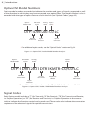
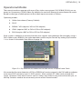
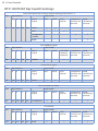
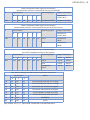
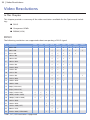
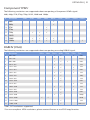
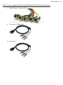
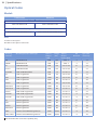
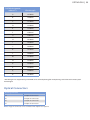
Optiva DVI Product Manual & User’s Guide OTP-1DVIT2AT OTP-1DVIR2AR 2 | Table of Contents Optiva DVI Product Manual & User’s Guide EMCORE Part Number: OTP_1DVI2A_Manual Revision: 2011.05.04. Printed in USA. The information in this manual is subject to change without notice or obligation. Copyright © 2011 EMCORE. All Rights Reserved. This document may not be reproduced in any form without written permission from EMCORE. Reproduction or reverse engineering of software, firmware or other digital media is prohibited. Notice The material in this manual is furnished for informational use only. It is subject to change without notice and should not be construed as commitment by EMCORE. EMCORE assumes no responsibility or liability for errors or inaccuracies that may appear in this manual. Trademarks EMCORE & Opticomm are trademarks of EMCORE Corporation. All other trademarks not explicitly named are property of their respective owners and are used only for identification purposes. Optiva DVI | 3 Contact Information EMCORE Corporation 2015 Chestnut Street Alhambra, CA 91803 Phone: +1 626-293-3400 Sales: [email protected] Technical Support: [email protected] Customer service: +1 626-293-3744 Website: www.opticomm.com 4 | Table of Contents Table of Contents Introduction6 Overview . . . . . . . . . . . . . . . . . . . . . . . . . . . . . . . . . . . 7 Features . . . . . . . . . . . . . . . . . . . . . . . . . . . . . . . . . . . . 7 Optiva DVI Model Numbers. . . . . . . . . . . . . . . . . . . . . . . . . . . 8 Signal Codes. . . . . . . . . . . . . . . . . . . . . . . . . . . . . . . . . . 8 Documentation Terms & Conventions . . . . . . . . . . . . . . . . . . . . . . 9 Installation10 Before You Begin. . . . . . . . . . . . . . . . . . . . . . . . . . . . . . . 10 Static Discharge . . . . . . . . . . . . . . . . . . . . . . . . . . . . . . . . 10 Installing the OTP-1DVIT2AT and OTP-1DVIR2AR. . . . . . . . . . . . . . . . 11 Cabling for the OTP-1DVIT2AT and OTP-1DVIR2AR . . . . . . . . . . . . . . . 12 Powering on the OTP-1DVIT2AT and OTP-1DVIR-2AR. . . . . . . . . . . . . . 13 User Controls14 Operational Modes . . . . . . . . . . . . . . . . . . . . . . . . . . . . . . 15 Dip Switch Settings. . . . . . . . . . . . . . . . . . . . . . . . . . . . . 16 Video Resolutions20 DVI-D . . . . . . . . . . . . . . . . . . . . . . . . . . . . . . . . . . . . . 20 Component YPbPr. . . . . . . . . . . . . . . . . . . . . . . . . . . . . . . 21 RGBHV (VGA). . . . . . . . . . . . . . . . . . . . . . . . . . . . . . . . . 21 Video Mode Configuration22 Auto Detection of Video Modes . . . . . . . . . . . . . . . . . . . . . . . . 23 Cables Types & DDC Support. . . . . . . . . . . . . . . . . . . . . . . . . . 23 EDID . . . . . . . . . . . . . . . . . . . . . . . . . . . . . . . . . . . . . 28 Loading EDID defaults (Factory Settings). . . . . . . . . . . . . . . . . . . . 29 Firmware Updates30 Firmware Update Procedure. . . . . . . . . . . . . . . . . . . . . . . . . . 31 Optiva DVI | 5 Specifications32 Optiva Insert Cards . . . . . . . . . . . . . . . . . . . . . . . . . . . . 33 Technical Specifications. . . . . . . . . . . . . . . . . . . . . . . . . . 33 Optical Codes. . . . . . . . . . . . . . . . . . . . . . . . . . . . . . . 34 Service Information36 Troubleshooting. . . . . . . . . . . . . . . . . . . . . . . . . . . . . 37 Fiber Optic Installation. . . . . . . . . . . . . . . . . . . . . . . . . . 37 Tools & Test Equipment Needed. . . . . . . . . . . . . . . . . . . . . . 37 Optical Cable Connections . . . . . . . . . . . . . . . . . . . . . . . . 39 Testing and Troubleshooting Steps For Installed Cable Plants. . . . . . . . 39 Troubleshooting Fiber. . . . . . . . . . . . . . . . . . . . . . . . . . . 40 Hints for Troubleshooting Fiber . . . . . . . . . . . . . . . . . . . . . . 41 Patch Cords . . . . . . . . . . . . . . . . . . . . . . . . . . . . . . . . 41 Connecting Optiva . . . . . . . . . . . . . . . . . . . . . . . . . . . . 42 Troubleshooting Optiva. . . . . . . . . . . . . . . . . . . . . . . . . . 42 Cable Plant Problems. . . . . . . . . . . . . . . . . . . . . . . . . . . 43 Electrical Interfaces. . . . . . . . . . . . . . . . . . . . . . . . . . . . 44 SNMP Monitoring and Control. . . . . . . . . . . . . . . . . . . . . . . 44 LED Status Indicators. . . . . . . . . . . . . . . . . . . . . . . . . . . 44 Warranty and Repair Policy. . . . . . . . . . . . . . . . . . . . . . . . 45 6 | Introduction Introduction In This Chapter This chapter contains the following sections: Overview OTP-1DVIT2AT Functional Block Diagrams OTP-1DVIR2AR Functional Block Diagrams Documentation Terms and Conventions A Word of Thanks Congratulations on choosing Optiva Optical Converters. By choosing an Optiva product, you have joined a growing family of professionals who appreciate the enhanced performance and ultimate versatility that Optiva products provide. Your Optiva cards are part of a full line of video transport and processing products within the Optiva Platform. This fiber optic transport system is backed by EMCORE’s experience in engineering and design expertise since 1984. The engineers at Emcore have designed your new OTP-1DVIT2AT and OTP-1DVIR2AR cards to conveniently fit into your overall working environment. Our commitment to product excellence allows us to design products that provide the highest performance quality, reliability and versatility in their respective product categories. Should you have a question about the installation or operation of your Optiva cards, please contact us at the numbers listed on the front of this manual. Optiva DVI | 7 Overview Optiva OTP-1DVIT2AT and OTP-1DVIR2AR cards are capable of carrying digital or analog video signals across a wide variety of resolutions up to 2560x1600. With support for both VESA and SMPTE video signals, the OTP-1DVIT2AT and OTP-1DVIR2AR are the ideal solution for professional video/audio and optionally, KVM applications. The OTP-1DVI2A cards provide the ability to transport digital video signals over a fiber optic link, providing longer transport distances. The electrical to optical (OTP-1DVIT2AT) and optical to electrical (OTP-1DVIR2AR) conversions use specific small form-factor pluggable (SFP) transceivers. The transmit card accepts DVI, VGA, RGBHV, RGsB (sync on green) or Component YPbPr as an input signal and will output any of those signals on the receiver card allowing for seamless format conversion across the fiber link. LED indicators on the front of the card identifies incoming video and displays the status of the optical link. The OT-CC or OT-DTCR series enclosures are used with OTP-1DVI2A products. The transmitter and receiver each occupy 1 slot in any of the enclosures. Using the OT-CC-16 allows up to 16 channels of video in a 3RU space. The XX designator at the end of the model number is meant to indicate one of SC, FC, ST or LC optical connectors. Features The following features are standard for Optiva OTP-1DVIT2AT and OTP-1DVIR2AR cards. Uses all-digital processing for crystal clear picture with no signal degradation Convert Analog -> Digital or Digital -> Analog across the fiber optic link Keyboard/Mouse/Serial Data Extension (KVM) (See model: OTP-1DVI2A1D1KM) Multimode or Singlemode fiber options (up to 43 miles/70 km over one fiber) Supports single / dual-link DVI resolutions up to 2560 x 1600 Supports VGA resolutions up to 1920 x 1200 Supports Component Video (YPbPr) up to 1080p H & V Sync Frequency range of 50 to 85 Hz 1/8” (2.5mm) Stereo Audio Connector Standard DVI-I video connector Choice of optical connectors (LC, SC, FC, ST) Choice of enclosure styles 3-Year Warranty 8 | Introduction Optiva DVI Model Numbers Optiva model numbers are coded to indicate the number and types of signals supported as well as the direction in which they may be transported over optical fiber. The model number is also is encoded with the type of optics that are used in the link (see “Optical Codes,” page 35). Optiva® Model Prefix DVI Video Signal Analog Audio Optics Code* OTP-1DVIT2AT-C0-LC Number of Channels Signal Direction Optical Connector * For additional optics codes, see the “Optical Codes” section on Pg. 34 Figure 1.1: Optiva DVI / Audio Model Number Analysis Optiva® Model Prefix DVI Video Signal Analog Audio Optics Code* OTP-1DVIT2AT1DTR1KMTR-C0/C0-LC Number of Channels RS-232 Serial Data Keyboard/ Mouse Optical Connector Signal Direction * For additional optics codes, see the “Optical Codes” section on Pg. 34 Figure 1.2: Optiva DVI / Audio / KVM Model Number Analysis Signal Codes Each Optiva model includes a “T” (for Transmit), “R” (for Receive), “TR” (for Transmit and Receive, i.e. Duplex Operation), or “RT” (for Receive and Transmit, i.e. Duplex Operation in the reverse side) to indicate the function carried out by each card. These codes also indicate the connection sequence of the electrical signals for optical transmission. Optiva DVI | 9 Documentation Terms & Conventions The following terms and conventions are used throughout this manual: “Chassis” or “Enclosure” refers to the OT-CC or OT-DTCR frame that houses the Optiva cards. “Module”, and “Card” refer to Optiva pluggable devices within Optiva enclosures, including all components and switches. “System” and “Video system” refer to the mix of interconnected production and rack equipment in your environment. The “Operating Tips” and “Note” boxes are used throughout this manual to provide additional user information. 10 | Installation Installation Before You Begin Before proceeding with the instructions in this chapter, make sure that your Optiva chassis is properly installed according to the instructions in the Optiva Series Product Manual. Static Discharge When installing your Optiva product, please be aware that static electricity is a potential cause of damage to any electronic device: ESD Susceptibility Static discharge can cause serious damage to sensitive semiconductor devices. Avoid handling circuit boards in environments where static electricity can be generated (such as carpeted areas and when wearing synthetic fiber clothing). Always exercise proper grounding precautions when working on circuit boards and related equipment. Unpacking Carefully unpack each Optiva card from its shipping container. If the unit is damaged or items are missing, contact your sales representative or EMCORE directly. Working with Fiber Optic Connectors Keep the following in mind when working with fiber optic connectors: You must clean a connector every time you insert it into a device or mating sleeve. All exposed surfaces of the ceramic ferrule must be clean. Follow standard professional practices for cleaning fiber optic connectors. Connectors must always be inserted into a device or have a dust cap on. A poor optical connection is often similar to a poor electrical connection. If you experience poor optical performance, try removing the connector, cleaning it thoroughly and then reinserting it. A bad connection can result in signal instability, high loss, or a noisy signal. Optiva DVI | 11 Installing Optiva Cards This section describes how to properly install a card into an Optiva chassis. Important Laser Safety Measures: Turn off all laser sources before attempting installation. High power visible or invisible (infrared, ultraviolet) laser light can cause permanent eye injury. Never look down the barrel of a connected fiber or device transmitting an optical signal as it is potentially damaging. CAUTION LASER RADIATION AVOID DIRECT EXPOSURE CLASS 1 LASER PRODUCT Use the following procedure to install Optiva cards in an Optiva chassis: 1. Ensure that the exposed surface of the ceramic ferrule of the connector is clean. Refer to the section “Working with Fiber Optic Connectors” on page 10 for more information. 2. Hold the card by the edges and carefully align the card edges with the slots in the frame. 3. Fully insert the card into the frame until the rear connection plug is properly seated in the chassis backplane. You will feel a click when the card is properly mated with the backplane. Make sure that the EMI gaskets (if present) do not snag or get bent during this process. 4. Tighten the 2 screws on the top and bottom to secure the card in the slot. 5. Remove the dust cap from the fiber port connector on the card faceplate. 6. When the card’s RED LED is lit on each card, it means power is present. Note that on unidirectional fiber links the RECEIVER’s GREEN LED will not light until optical link communication is obtained. 7. Ensure the ceramic ferrule of the fiber port connector is clean. 8. Cable the insert card as outlined in the section “Cabling for the OTP-1DVIT2AT and OTP-1DVIR2AR” on page 12. This completes the proper installation of Optiva cards in an Optiva Platform chassis. 12 | Before You Begin Cabling for OTP-1DVIT2AT and OTP-1DVIR2AR Cards This section provides information for connecting cables to the installed insert cards in the Optiva Platform enclosure. Connect the input and output cables as indicated in the following diagrams. The optical connectors are designed for a direct interface connection. All fiber interfaces are either singlemode or multimode fibers; please refer to the Optical Code chart to confirm fiber type. The OTP-1DVI has DVI-I Dual link connector and will work with any standard single (provided with the product) or dual link cables. For VGA, an adapter is required (provided with the product). Notice: Every time you are required to insert a fiber connector into a device or mating sleeve, you must clean the connector. All exposed surfaces of the ceramic ferrule must be clean. Follow your facility practices of cleaning fiber optic connectors. OTP-1DVIT2AT Cabling Overview The OTP-1DVIT2AT provides the following connections: DVI, RGBHV or YPbPr Input (May require adapter) Stereo Analog Audio Input Keyboard, Mouse & RS-232 Input Optical Output (ST, FC, ST or LC) OTP-1DVIR2AR Cabling Overview The OTP-1DVIR2AR has the following connections available: DVI, RGBHV or YPbPr Output (May require adapter) Stereo Analog Audio Output Keyboard, Mouse & RS-232 Output Optical Input (ST, FC, ST or LC) Optiva DVI | 13 Powering on OTP-1DVIT2AT and OTP-1DVIR2AR Cards This section provides instructions for powering up your Optiva cards for the first time. Initial Power Up Important: Please use the installation procedure below. Improper or no operation may result if the start-up sequence is not correctly followed. Step 1 : Verify that the system power is off. Make sure that insert card is properly inserted and the card is seated in the enclosure. Remove the optical dust cover(s) and connect optical port (LC/FC/DLC/ST/SC) to appropriate fiber cable (SMF or MMF {50µm or 62.5µm}). Make sure the connectors are fully engaged. If your system has Dual LC connectors please follow the label on the side of the Optiva card for fiber polarity (TX vs RX) and connect the TX port on the Transmitter to the RX port of the receiver side. Step 2: With system power turned off, connect the Transmitter unit to the source by the appropriate cable (see “User Control” Chapter). A single link DVI-D copper cable and VGA to DVI-I adapter are included with the product. If your Optiva DVI product configuration includes Keyboard, Mouse and Data (RS-232) you should also make the appropriate electrical connections at this time for the signals you wish to use (Keyboard/Mouse cables are included only when you order a KVM option). You must connect the transmitter’s Keyboard/Mouse cables to the computer while it’s off, so that proper input device detection will occur. Step 3: In the same way as above, connect the Receiver unit to the monitor/display. If your Optiva DVI product configuration includes Keyboard, Mouse and RS-232 Data, please connect your peripherals to the provided breakout cable and plug it into the Optiva DVI Receiver unit. Step 4: Turn the enclosure power for the transmitter/receiver unit on and verify that status LEDs on transmitter and receiver are green. Turn on your input source and output monitor. Based on the connected cable type the system will auto detect and determine your video mode, then it will pass the video signal from the source to the display. Important note: It is essential to use the correct cable, otherwise the system will pass a video mode that may not be compatible with the display. For manual cable configurations, please refer to the section “Operational Modes” on page 15. This completes the procedure to powering on the OTP-1DVIT2AT and OTP-1DVIR2AR. Your system is now operational and ready for use. 14 | User Controls User Controls In This Chapter This chapter provides a general overview of the user controls available on the Optiva OTP-1DVIT2AT and OTP-1DVIR2AR cards. The following topics are discussed: Operational Modes Dip Switch Settings OPTIVA DVI | 15 Operational Modes The transmit card can operate with one of four video source types: DVI, RGBHV, RGsB (sync on green) or Component (YPbPr) Video. By default, the card will attempt to auto-detect the mode based on the type of cable present at the video input connector as follows: Operating modes: 1. Cable Auto-detect (Factory Default) 2. DVI-D 3. RGBHV / VGA (requires VGA to DVI adapter) 4. YPbPr (requires BNC to DVI or RCA to DVI adapter) 5. RGsB (requires BNC to DVI or RCA to DVI adapter) If the system is cabled in a manner that does not support auto-detection (for example, using a DVI-I cable to pass RGBHV), the video operation mode may be “forced” by setting Dip Switches 1–4 as shown in the tables that follow on page 16. Figure 2.1: Dip Switches are located on the back corner of Optiva Insert Cards Also note that for auto detection of DVI or RGBHV to function properly, the DVI cable or adapter must have 5VDC present on pin 14 (DDC power). Most modern PC video cards provide this signal. However, some other sources such as scalers and switches may not connect this pin, so the Dip Switches need to be set correctly to one of the “forced modes.” 16 | User Controls OTP-1DVIT2AT Dip Switch Settings Auto Cable Detection (Factory Default Setting) Dip Switch 1-4 Hex 0 Dip Switch # Input Cable 4 3 2 1 Input Signal DVI-I Off Off Off Off DVI-D DVI-D VGA (DVI-A) Component (5V DDC not present) RGsB (5V DDC not present) Component (YPbPr) RGsB VGA Force RGBHV signal Hex 5h Dip Switch # Input Cable 4 3 2 1 Input Signal Off On Off On RGBHV DVI-I DVI-D VGA-5BNC Component (Adaptor (5V DDC not required) present) RGsB (5V DDC not present) Force DVI-D signal Hex Dip Switch # Input Cable 4 3 2 1 Input Signal DVI-I 7h Off On On On DVI-D Hex Dip Switch # DVI-D VGA (DVI-A) Component (5V DDC not present) RGsB (5V DDC not present) VGA (DVI-A) Component (5V DDC not present) RGsB (5V DDC not present) Component (5V DDC not present) RGsB (5V DDC not present) Force Component YPbPr Input Cable 4 3 2 1 Input Signal 9h On Off Off On Component Hex Dip Switch # DVI-I DVI-D Force RGsB 13h Input Cable 4 3 2 1 Input Signal On On Off On RGsB DVI-I DVI-D VGA (DVI-A) Optiva DVI | 17 DIP Switch # 10: Shall be on when duplex optics is selected, this enables bidirectional link. This is applicable for bidirectional optics only! DIP Switch # 9: When on it prevents EDID copy. Dip Switch # 8, 7, 6, 5: Reserved - should be in off position. 18 | User Controls OTP-1DVIR2AR Dip Switch Settings The Optiva DVI system converts video input from the transmit side into any selected video formats on the receive side. Operating modes: 1. Cable Auto-detect (Factory Default) 2. DVI-D 3. RGBHV / VGA (Requires DVI-to-VGA adapter) 4. YPbPr (Requires DVI-to-BNC adapter) 5. RGsB (Requires DVI-to-VGA adapter) 6. Color space conversion Factory Default Setting of Dip-Switch 1- 6 Hex 0 Dip Switch# 6 5 4 Off Off Off 3 2 1 Incoming Output Cable/Signal: VideoSignal DVI-I DVI-D VGA Component (YPbPr) Off Off Off DVI-D DVI-D DVI-D VGA Component RGsB DVI-D DVI-D VGA Component (YPbPr) Component DVI-D DVI-D (YPbPr) VGA Component (YPbPr) RGsB VGA DVI-D DVI-D RGsB Force DVI-D signal on the output (automatically converts incoming BT.601 stream to RGsB) # 01h Dip Switch # 5 4 3 2 1 Incoming Video Signal Output Connector 6 DVI-I DVI-D Off Off Off Off Off On DVI-D DVI-D DVI-D VGA DVI-D DVI-D Component YPbPr DVI-D DVI-D Force VGA (RGBHV) signal on the output (automatically converts incoming BT.601 stream to RGsB) # 01h Dip Switch # Incoming Video Signal 6 5 4 3 2 1 Off Off Off Off Off On RGsB (5V DDC not present) Output Connector DVI-A (VGA w/5V DDC) DVI-D RGBHV VGA RGBHV Component YPbPr RGBHV Optiva DVI | 19 Force Component YPbPr signal on the output (automatically converts incoming BT.709 stream to RGsB) # Dip Switch # 24h Incoming Signal 6 5 4 3 2 1 On Off Off On Off Off Output Connector Component (YPbPr) RCA ComponentYPbPr Component YPbPr Force Component YPbPr signal on the output (automatically converts incoming RGsB stream to BT.709 stream) # Dip Switch # 34h Incoming Signal 6 5 4 3 2 1 On On Off On Off Off Output Connector Component (YPbPr) RCA DVI-D Component YPbPr VGA Component YPbPr Force ‘Digital Separate syncs’ on the output (turn OFF Component video on the output) # Dip Switch # 01h Incoming Signal 6 5 4 3 2 1 Off Off Off Off Off On Output Connector DVI-I DVI-D DVI-D DVI-D DVI-D VGA DVI-D DVI-D Component YPbPr DVI-D DVI-D Dip Switch Settings for Color Space Conversion on RX card # Dip Switch # Notes 6 5 4 7h On On On Convert RGsB to BT.601 (on analog) 6h On On Off Convert RGsB to BT.709 (on analog) 5h On Off On Convert BT.601 to RGsB (on digital) 4h On Off Off Convert BT.709 to RGsB (on digital) 3h Off On On Convert BT.601 to RGsB (on both) 2h Off On Off Convert BT.709 to RGsB (on both) 1h Off Off On RESERVED 0h On Off Off AUTO Dip Switch 10, 9, 8, 7: Reserved; should be in the off position . 20 | Video Resolutions Video Resolutions In This Chapter This chapter provides a summary of the video resolutions available for the Optiva card, including:: DVI-D Component YPbPr RGBHV (VGA) DVI-D The following resolutions are supported when transporting a DVI-D signal: # 100Hz 120Hz 1 640 x 480 Resolution 24Hz 25Hz 30Hz 50Hz 60Hz 72Hz 96Hz 2 800 x 600 3 852 x 480 4 1024 x 768 5 1024 x 852 6 1024 x 1024 7 1280 x 768 8 1280 x 1024 9 1360 x 765 10 1365 x 768 11 1366 x 768 12 1365 x 1024 13 1400 x 1050 14 1600 x 1200 15 480p (720 x 483) 16 576p (720 x 576) 17 720p (1280 x 720) 18 1080i (1920 x 1080) 19 1080p (1920 x 1080) 20 1864 x 1050 1680 x 1050 22 1920 x 1200 (CVT) 23 2048 x 1536 24 2560 x 1600 (CVR2560D) * DMT, CVT, CVR resolutions supported 21 Optiva DVI | 21 Component YPbPr The following resolutions are supported when transporting a Component YPbPr signal: 480i, 480p, 576i, 576p, 720p, 1035i, 1080i and 1080p. # Resolution 1 480i 2 480p 3 576i 4 576p 5 720p 6 1035i 7 1080i 8 1080p 24Hz 25Hz 30Hz 50Hz 60Hz 72Hz 96Hz 100Hz 120Hz RGBHV (VGA) The following resolutions are supported when transporting an analog RGBHV signal: # Resolution 1 640 x 480 25Hz 30Hz 50Hz 60Hz 2 720 x 576 3 800 x 600 72Hz 75Hz Type DMT 576p/i DMT 4 1024 x 768 CVT 5 1152 x 720 CVT 6 1152 x 864 DMT 7 1366 x 768 CVT 8 1280 x 720 720p 9 1280 x 960 CVT 10 1280 x 1024 DMT 11 1224 x 768 12 1400 x 1050 13 1536 x 960 14 1680 x 1050 15 1920 x 1080 16 1920 x 1080i 17 1864 x 1050 18 1600x 1200 CVT CVT CVT DMT 1080p 1080i CVT DMT/CVT * DMT, CVT resolutions supported. * For non-compliant VESA resolutions, please contact Emcore or use EDID copy function. 22 | Video Mode Configuration Video Mode Configuration In This Chapter This chapter provides an overview of the user settings/configurations available with your Optiva cards. The following topics are discussed: Auto detection of video modes Cable types and DCC support EDID Loading EDID defaults (Factory Settings) Optiva DVI | 23 Auto Detection of Video Modes EDDC (Enhanced Display Data Channel) is a communication protocol between HOST (DVI-RX card) and Computer Display. This protocol makes it possible for DVI-RX card to communicate with the DISPLAY device and understand its capabilities and supported graphic modes. It is critical to use appropriate cable types when auto sensing video modes for DVI, VGA or component video applications. It is possible to force a mode of operation on DVI-TX card. Please refer the chapter on “DIP SWITCH Settings” on the previous pages. For Quick reference (when auto-sensing the video format): 1. DVI-I cable defaults to DVI-D. 2. DVI-D cable defaults to DVI-D. 3. DVI-A cable defaults to VGA. 4. VGA cable (DDC +5V present) defaults to RGBHV. 5. VGA cable (DDC+5V missing) defaults to Component YPbPr mode. 6. RGBHV cable (DDC+5V missing) defaults to Component YPbPr mode. Cables Types & DDC Support This section reviews the various cable types, connectors and supported video modes. DDC is supported for the following DVI/VGA cable types: 1. DVI-I Cable (supports DDC): 2. DVI-A Cable: 24 | Video Mode Configuration 3. DVI-D Cable 4. VGA Cable: Optiva DVI | 25 DDC is not supported for the following DVI/VGA cable types: 1. RGBHV (doesn’t support DDC): 2. Component YPbPr cable 3. RGsB cable 26 | Video Mode Configuration DDC Connections on DVI-I Dual Link Connector Pin Description 1 DVI TMDS PAIR #2 DATA 2- 2 DVI TMDS PAIR #2 DATA 2+ 3 DVI TMDS DATA2/4 Shield 4 DVI TMDS PAIR #4 DATA 4- 5 DVI TMDS PAIR #4 DATA 4+ 6 SCL (DDC Clock line) 7 SDA (DDC Serial Data line) 8 Analog vertical sync (VSync VGA) 9 DVI TMDS PAIR #1 DATA 1- 10 DVI TMDS PAIR #1 DATA 1+ 11 DVI TMDS DATA 1/3 Shield 12 DVI TMDS PAIR #3 DATA 3- 13 DVI TMDS PAIR #3 DATA 3+ 14 +5V DDC (critical for Optiva Video Format auto detection feature) 15 Ground (for +5V Power) 16 DVI Hot Plug Detect (critical for OptivaVideo Format auto detection feature) 17 DVI TMDS PAIR #0 DATA 0- 18 DVI TMDS PAIR #0 DATA 0+ 19 DVI TMDS DATA 0/5 Shield 20 DVI TMDS PAIR #5 DATA 5- 21 DVI TMDS PAIR #5 DATA 5+ 22 TMDS CLOCK SHIELD 23 TMDS CLOCK+ DIGITAL CLOCK+ (for primary and secondary link) 25 TMDS CLOCKDIGITAL CLOCK- (for primary and secondary link) C1 Analog Red (Red VGA) C2 Analog Green (Green VGA) C3 Analog Blue (Blue VGA) C4 Analog HSync (HSync VGA) Optiva DVI | 27 DDC Connections on VGA D-SUB Connector Pin Description 1 Red VGA 2 Green VGA 3 Blue VGA 4 Reserved 5 Ground 6 Red Ground 7 Green Ground 8 Blue Ground 9 +5V DDC (critical for Optiva Video Format auto-detection feature) 10 Sync Ground 11 Monitor ID0 (optional) 12 SDA (DDC Serial Data line) 13 HSync VGA 14 VSync VGA 15 SCL (DDC Clock line) 28 | Video Mode Configuration EDID The Optiva DVI is pre-configured with factory EDID (extended display identification data) that addresses all supported resolutions. However in some cases, there is a need to copy the EDID of the display into the TX side . The following procedures describe how to re-program EDID. Before proceeding: 1. DDC (+5V) power line, SCL (DDC Clock) line and SDA (DDC Serial Data) line are required to query the EDID of Display/Monitor. 2. Make sure that the DVI cable being used supports DDC lines. Procedure Copy EDID of DISPLAY to DVI-RX card. This will emulate EDID (of DISPLAY) from DVI-RX card to DVI-TX card. Note: this is done automatically 1. Install DVI-RX card in a chassis. 2. Make sure that DVI-RX card is POWERED OFF. 3. Use any DVI (or VGA) cable that supports DDC to make a connection between DVI-RX card and the Display. 4. POWER ON DVI-RX card. 5. As soon as the card POWERS-UP, the STATUS or ALERT LED will light up and display the (default) status of Optical Sync. 6. If new EDID data is available, the Green LED will blink on DVI-RX card indicating the progress of EDID-copy from DISPLAY device to DVI-RX card. 7. Once the EDID-copy process has completed, the Green LED stops blinking and shows the status of Optical Sync (default). Note: whenever DVI-RX card detects a new Display, new EDID data is copied (almost) instantaneously. Emulate EDID (of Display) from DVI-RX card to DVI-TX card 1. Install DVI-RX card in a chassis. 2. Make sure that DVI-RX card is POWERED OFF. 3. Make sure that DVI-TX card is POWERED OFF. 4. Use any DVI (or VGA) cable that supports DDC to make a connection between DVI-RX card and DVI-TX card. 5. Don’t supply any POWER to the DVI-TX card. To Emulate EDID, power is supplied by +5V DDC power line (from DVI-RX card). 6. POWER-ON DVI-RX card. 7. Green LED will blink on the RX card to indicate the status of EDID-emulation. 8. Green LED stops blinking and returns to its default status on completion of process. Optiva DVI | 29 Loading EDID defaults (Factory Settings) DVI-RX card: EDID data on DVI-RX card is updated when as a display/monitor is disconnected and re-connected. DVI-TX card: If, for some reason, the EDID-emulation procedure fails, factory default EDID settings can be loaded on DVI-TX card by connecting PS2-RS232 cable to the Serial port of computer and accessing the Service Menu using HYPETERMINAL. Accessing the Service Menu 1. Install DVI-TX card in a chassis. Turn POWER-OFF. 2. DVI-RX card doesn’t get affected by this process. If the Optical Sync is “OK,” there is no need to disconnect the fiber (or disturb the setup). 3. Connect the supplied PS2 Cable to DVI-TX card. 4. Connect the RS232 connector of PS2 cable to a serial port on the PC. 5. Make sure that PC is Powered ON. 6. Launch HYPERTERMINAL application and configure as: Bits per second: 115200 Data bits: 8 Parity: None Stop bits: 1 Flow Control: None 7. Click on the CALL icon to make connection with the RS232 port. 8. POWER-ON DVI-TX card. 9. Type the serial config key “EmcoreDviConfig.” (Upon power-up, you have 40 keystrokes to enter the right key. More than 40 strokes will return the card into regular operation mode). 10. SERVICE MENU should appear. If it doesn’t, recycle power and enter serial config key again. Load default EDID settings from Service Menu 1. Log-in to the service menu. See “Accessing the Service Menu” for notes/procedure. 2. Selecting Menu option # 3 from the service menu allows you to reset EDID settings to factory defaults. 3. Follow the on-screen instructions to load default EDID settings. 4. When the default EDID settings are loaded, LED D29 (located on the rear side of the card) blinks green. 5. Service Menu will return to the default screen when EDID copy is complete. 6. Selecting Menu option # 4 will restart DVI-TX board (or the DVI link if fiber is connected). 30 | Firmware Updates Firmware Updates In This Chapter This chapter provides an overview of the firmware update process for the Optiva cards. The following topics are discussed: Updating the firmware Optiva DVI | 31 Firmware Update Procedure 1. Install DVI-TX card in the chassis. Do not POWER UP. 2. Install DVI-RX card in the chassis. Do not POWER UP. 3. Connect optical-fiber between the cards. 4. POWER-UP DVI-TX card and DVI-RX card (in any order). 5. If the DVI cable is connected, it need not be disconnected. 6. The LED must be solid-green on both TX and RX card at this time. This confirms that optical sync is OK. The firmware update process for the RX card is initiated over fiber. If for any reason the update process fails on either of the cards, you can try again. Note: Don’t turn power off during firmware update . 7. Log-in to the service menu. Refer “Accessing the Service Menu” for notes/procedure. 8. As soon as the SERVICE menu screen shows up, DVI-video playback is interrupted. It will resume as soon as the firmware process is completed. 9. Check firmware revision (Menu Option #1). The firmware being updated must be newer than the one already installed on card. 10. Select “update firmware” Menu Option #4. 11. Enter “y” to continue. Green LED blinks on DVI-TX card and DVI-RX card. 12. Green LED slow blinks to indicate that the card is in programming mode. 13. Green LED fast blinks to indicate the receipt of binary file. 14. Follow the on-screen instructions and transfer the file (*.bin) using X-Modem transfer protocol. 15. Be patient with the firmware update process. It may take up to 15 minutes to complete. 16. This process will also update the firmware on RX card (as mentioned earlier). 17. The boards should restart automatically. 18. Upon POWER-UP, Green LED on the TX-card will blink longer than the RX-card (about 2 minutes). This is normal. 19. DVI-Video playback should continue (if connected). What to do if an update fails: If update failed due to loss of power or optical connection, the failed card will restart with a blinking red status LED, indicating that it has booted in fail-safe mode. If the TX card upload failed, the serial terminal will display a message that the card is operating in recovery mode (the user may have to press the ‘enter’ key a few times for this to be displayed). To retry the upload, press ‘y’ twice as prompted to begin the process, then proceed from step 6 above as normal. If only the RX upload failed, no message will be displayed, but the RX status LED will still be blinking red. To retry upload, simply repeat the original process starting with step 4. If upload fails on the second try, there may be a hardware or optical issue, and the user should contact Emcore Technical Support. 32 | Specifications Specifications In This Chapter This chapter includes the technical specifications for the Optiva cards. Note that, since Emcore is involved in ongoing product and design improvements, specifications are subject to change without notice. The following topics are discussed: OTP-1DVIT2AT Technical Specifications OTP-1DVIR2AR Technical Specifications Optical Codes Optiva DVI | 33 Optiva Insert Cards General Dimensions & Weight Insert Card (IC): 7.267” L x .787” W x 5.055” H; 11 oz. 18.458 cm x 1.999 cm x 12.839 cm; 311.845 gm Operating Temperature -20° C to +50° C Storage Temperature -40° C to +85° C Humidity 0 to 95% non-condensing Operating Voltage 9-12 VDC Shock & Vibration Sinusoidal, 5 to 200Hz at 1.5g peak System Latency Less than 1ms MTBF >100,000 Hours @ 25°C, Ground Benign, per MIL-HDBK-217F, at card level Regulatory CE, CSA, FCC Part 15 OTP-1DVIT2AT & OTP-1DVIR2AR Technical Specifications Video Specifications Values Standards DVI 1.0/VESA Resolutions (See “Video Resolutions” section) Connector DVI-I (VGA adapter available) Color Depth 24 Bit VGA Video Bandwidth 780 MHz Analog Video Output Level 1V p-p Video Signal-to-Noise Ratio >55 dB Audio Specifications Values Channels 24-Bit Stereo Audio Impedance 47k Ohm Unbalanced Audio Levels 2V p-p Max Frequency Response 20 Hz to 20 KHz (±0.1 dB) Signal-to-Noise Ratio > 85 dB @ 1KHz (weighted) Total Harmonic Distortion < 0.1% @ 1KHz Connector Type 1/8” Stereo Headphone Jack 34 | Specifications Optical Codes Models Transmitter Receiver DVI with audio: OTP-1DVIT2AT-YY-XX OTP-1DVIR2AR-YY-XX DVI with audio, keyboard/mouse and serial data: OTP-1DVIT2AT1DTR1KMTR-YY-XX OTP-1DVIT2AT1DRT1KMRT-YY-XX Note: YY refers to the optics XX refers to the optical connector Codes Ordering Code YY) Wavelength (nm) & Fiber Type C0 850 Multimode C0/C0* 850 Multimode C1 Range (km) Typical Output Power (dBm) RX Overload 7dB 0.2 -10 to -3 -3 -17 7dB 0.2 -10 to -3 -3 -17 1310 Multimode 5dB 0.8 -5.5 to -0.5 0 -17 C1/C1* 1310 Multimode 5dB 0.8 -5.5 to -0.5 0 -17 C1/C3M* 1310/1550 Multimode 5dB 1.5 -2.5 to 2.5 0 -17 C2 1310 Singlemode 7dB 10 -5.5 to -0.5 0 -17 C2D 1310 Singlemode 12dB 20 -5.5 to -0.5 0 -18 C2H 1310 Singlemode 25dB 60 -2.5 to 2.5 8 -28 C2/C2* 1310 Singlemode 7dB 10 -5.5 to -0.5 0 -17 C2D/C2D* 1310 Singlemode 12dB 20 -5.5 to -0.5 0 -18 C2H/C2H* 1310 Singlemode 25dB 60 -2.5 to 2.5 0 -18 C2/C3* 1310/1550 Singlemode 12dB 20 -2.5 to 2.5 0 -17 C2/C3D* 1310/1550 Singlemode 17dB 40 -2.5 to 2.5 -9 -21 C2/C3H* 1310/1550 Singlemode 25dB 60 -2.5 to 2.5 -8 -28 C3 1550 Singlemode 17dB 40 -2.5 to 2.5 0 -21 C3D 1550 Singlemode 25dB 60 -2.5 to 2.5 8 -28 C3/C3* 1550 Singlemode 17dB 40 -2.5 to 2.5 0 -20 C3D/C3D* 1550 Singlemode 25dB 60 -2.5 to 2.5 8 -28 L4X3 1270 to 1610 CWDM Singlemode 25dB 20-70 -2.5 to 2.5 -8 -28 L4X3/L4X3* 1270 to 1610 CWDM Singlemode 25dB 20-70 -2.5 to 2.5 -8 -28 * For DVI model with serial data capability only Optical Budget ((dB)) Typical RX Sensitivity Optiva DVI | 35 CWDM designator where X = Wavelength A 1270nm B 1290nm C 1310nm D 1330nm E 1350nm F 1370nm* G 1390nm* H 1410nm I 1430nm J 1450nm K 1470nm L 1490nm M 1510nm N 1530nm O 1550nm P 1570nm Q 1590nm R 1610nm * Wavelength not supported by the MDM series of multiplexing/de-multiplexing cards due to the water-peak wavelengths Optical Connectors Ordering Code (XX) ST ST Optical Connector FC FC Optical Connector SC SC Optical Connector LC LC Optical Connector Note: Single LC connector is not available with duplex laser options 36 | Service Information Service Information In This Chapter This chapter contains the following sections: Toubleshooting Checklist Fiber Optic Installation Tools and Test Equipment Needed Optical Cable Connection Testing and Troubleshooting Steps for Installed Cable Plants Troubleshooting Fiber Hints for Troubleshooting Fiber Patch Cords Connecting Optiva Troubleshooting Optiva Cable Plant Problems Electrical Interfaces SNMP Monitoring and Controls LED Status Indicators Warranty & Repair Policy Optiva DVI | 37 Troubleshooting Routine maintenance to this Optiva product is not required. In the event of problems with your cards, the following basic troubleshooting checklist may help identify the source of the problem. If the product still does not appear to be working properly after checking all possible causes, please contact your EMCORE products distributor, or the Technical Support department at the numbers listed under the contact information in the front part of the manual. 1. Visual Review — Performing a quick visual check may reveal many problems, such as connectors not properly seated or loose cables. Check the card, the enclosure, and any associated peripheral equipment for signs of trouble. 2. Power Check — Check the power indicator LED on the enclosure’s front panel for the presence of power. If the power LED is not illuminated, make sure the power cable is connected to a power source and verify that power is available at the power main. Confirm that the power supplies are fully seated in their slots. If the power LED is still not illuminated, replace the power supply with one that is working properly. 3. Input Signal Status — Verify that source equipment is operating correctly and that a valid signal is being supplied. 4. Output Signal Path — Verify that destination equipment is operating correctly and receiving a valid signal. 5. Unit Exchange — Exchanging a suspect unit with a unit that is known to be working correctly is an efficient method for locating problems in individual components. Fiber Optic Installation Once a fiber optic cable plant, network, system or link is installed, it needs to be tested for four reasons: 1. To ensure the fiber optic cable was properly installed to specified industry standards. 2. To ensure the equipment intended for use on the cable plant will operate properly on the cabling. 3. To ensure the communications equipment is working to specifications. 4. To document the cable plant and network for reference in case of future problems. Tools & Test Equipment Needed The following tools are needed to test and troubleshoot the fiber optic cable plant, system or link properly: 1. Optical Loss Test Set or power meter and test source with optical ratings matching the specifications of the installed system (fiber type and transmitter wavelength and type) and proper connector adapters. 2. An OLTS that merely tests cable plant loss may not include a calibrated power meter needed for testing transmitter and receiver power, so a calibrated power meter and source are a better choice for link or system testing. 3. Reference test cables with proper sized fiber and connectors and compatible mating 38 | Service Information adapters of known good quality. These do not need to be “reference quality,” but should be in good condition, generally defined as having connector losses of less than 0.5 dB. 4. Visual fiber tracer and/or visual fault locator (VFL) 5. Optional: OTDR with long launch cable (100 m for Multimode, 1 km or more for singlemode) Optiva DVI | 39 Optical Cable Connections All fiber cable plants require certain basic tests to insure they were installed correctly and meet expected performance values. The most valuable data one can have for troubleshooting is the installation documentation. What Can Go Wrong? There are a number of possible problems with fiber optic cable installations that can be caused by installation procedures. The most common include: »»Damage to the cable during installation caused by improper pulling techniques (such as not pulling the fiber cable by the strength member) excess tension, tight bends under tension, kinking or even too many bends. Most of these problems will be seen on all fibers in the cable. »»Damage to the fibers in the cable during cable preparation for splicing or termination. Fibers may be broken or cracked during cable jacket or buffer tube removal or fiber stripping. This may affect all fibers in the cable or buffer tube or just one fiber. »»High loss splices caused by improper splicing procedures, especially poor cleaving on mechanical splices or improper programming of fusion splicers. Most fusion splicers give feedback on most problems if the operator is properly trained. Individual fibers can be damaged when being placed in splice trays or tubes of fibers damaged during placement in splice closures. »»High loss connectors may be caused by bad processes or damage after termination. Adhesive/polish connectors may have poor end finishes or cracks in the fiber at the end of the ferrule or internally. Pre-polished/splice connectors are generally high loss due to poor mechanical splicing processes during termination causing high internal loss. »»Dirt creating high insertion loss and physical damage. Testing And Troubleshooting Steps For Installed Cable Plants Before installation, it is advisable to test all cable as received on the reel for continuity using a visual tracer or fault locator. Cables showing signs of damage in shipment may need OTDR testing to determine if the cable itself is damaged. Obviously, no cable showing damage should be installed. Test insertion loss after installation. 1. After installation, splicing (if applicable) and termination, all cables should be tested for insertion loss using a source and meter or OLTS (optical loss test set) according to standards OFSTP-14 for multimode fiber, OFSTP-7 for singlemode fiber. 2. Generally cables are tested individually (connector to connector for each terminated section of cable and then a complete concatenated cable plant is tested “end-to-end”, excluding the patch cords that will be used to connect the communications equipment which are tested separately. 3. It is the concatenated cable test that is used to compare to the link power budget and communications equipment power budget to insure proper operation. 4. Insertion loss testing should be done at the wavelength of intended operation if 40 | Service Information known or at two wavelengths with appropriate sources . (e.g.: 1310nm/1550nm). 5. Unless standards call for bidirectional testing, double-ended testing with both launch and receive cables (OFSTP-7/14) is adequate. 6. Data on insertion loss of each fiber should be kept for future comparisons if problems arise or restoration becomes necessary. Recording data on a label inside the patch panel or enclosure is common practice. 7. Long cables with splices may be tested with an OTDR to confirm splice quality and detect any problems caused during installation, but insertion loss testing with an OLTS (light source and power meter) is still required to confirm end-to-end loss. Cables with insertion loss near expected values do not also need OTDR testing. Cables tested with an OTDR should have the data kept on file for future needs in restoration. Troubleshooting Fiber »»First determine if the problem is with one or all the fibers in the cable. If all fibers are a problem, there is a likelihood of a severe cable installation problem. If all fibers are broken or have higher than expected loss, an OTDR will show the location of the problem on longer cables but premises cables may be too short and need physical inspection of the cable run. If the problem is caused by kinking or too tight a bend, the cable will have to be repaired or replaced. »»High loss fibers have several potential causes, but bad splices or terminations are the most likely cause for field terminated cables. In some cases, using improper termination practices will result in high loss for all fibers, just as in kinking or bending losses, not just one fiber. »»Cables with a fiber or fibers showing very high loss or no light transmission at all should be tested for obvious breaks in the pigtail fiber or cable, generally at the splice or connector, with a visual fault locator or OTDR if of sufficient length (>100m). »»Testing for high loss should start with microscope inspection of terminations for proper polish, dirt, scratches or damage. »»If dirt appears to be the problem, clean the connectors and retest. »»If other connector damage is found on visual inspection, re-termination will prob- ably be necessary. Sometimes scratches can be polished out with diamond film by an experienced technician. »»Pre-polished splice connectors with internal splices will generally look OK when in- spected with a microscope unless damaged after installation. The most likely cause of loss with these connectors is high splice loss in the internal splice. They can be tested with a visual fault locator coupled into the fiber at the far end. High light loss will be seen as an illumination of the connector ferrule. »»If the reason for high loss is not obvious and the connectors are adhesive/polish style, the problem may be a fiber break in the back of the connector. A VFL (Visible fault locator) may help in finding fiber breaks, depending on the connector style and the opacity of the cable jacket. »»Splice loss problems can be pinpointed during OTDR testing. Confirmation with a VFL should be done if the length from the end of the cable is short enough (~2-3km) Optiva DVI | 41 where a VFL is usable. The VFL can find high loss splices or cracks in fibers caused by handling problems in the splice tray. Hints for Troubleshooting Fiber »»Having access to design specifications and installation documentation and specifications will greatly assist troubleshooting. »»If possible, interview the installer to help uncover processes that may lead to issues in installation, such as pulling methods, lubrication, intermediate pulls, splicing or termination methods (like improper field termination of singlemode which can lead to high loss and reflection even when connectors look OK in a microscope). Patch Cords Patch cords are short factory-terminated cables usually with standard heat-cured epoxy/polish connectors on each end. They are used to connect equipment to the cable plant and as reference cables for testing insertion loss. Most patch cord problems are connector problems, caused by damage due to handling or numerous matings when used as reference cables for testing other cables. Connectors may also be damaged by breaking fibers at the back of the connector due to excess stress during handling or by placing other equipment on top of them in enclosures or patch panels. All patch cords, especially those used as reference cables for insertion loss testing, should be tested for insertion loss »»Patch cords should be tested with an optical loss test set (optical power meter and source) using single-ended FOTP-171 methods with one reference cable used as a launch cable. »»This will test the connector mated to the reference cable and the fiber in the patch cord, which is short enough it should have no measurable loss »»Since the connector connected to the power meter will not be connected to fiber but presented directly to the detector of the power meter, it effectively has no loss. »»After testing in one direction, reverse the patch cord and test the other end. »»In both directions, factory-made patch cords should have a loss of less than 0.5 or whatever performance the user has specified with patch cord vendors. »»High loss connectors should be inspected with a microscope for dirt or damage. »»If other connector damage is found on visual inspection, re-termination will probably be necessary but may not be cost effective, so the patch cord should be replaced. Sometimes scratches can be polished out with diamond film by an experienced technician. »»Some optical loss test sets include fiber interfaces on both source and meter ports, so all testing is done double-ended, even if the cable under test is directly connected to an input port. A test set such as this makes reverse testing less effective, since reversing test direction may not have any significant effect. Test ports on an OLTS like this should be kept covered when not in use and cleaned periodically. Damaged fibers inside an OLTS will require factory repair. 42 | Service Information Connecting Optiva After the cable plant has been tested, the communications equipment should be properly connected using matching known-good patch cords. If the cable plant loss is within the loss budget of the equipment (including the loss of the patch cords), the communications link should work properly. If the link does not work, most likely potential problems are the following: »»Improper connections »»Cable plant problems »»Malfunctions of communications equipment Troubleshooting Optiva In most cases an optical problem will be indicated by a red LED indication on the receiver side. »»Improper connections. The system requires a transmitter be connected to a receiver, of course, so it is important to verify this connection for each link. Even if the cable plant is properly documented, fibers may have been crossed at intermediate connections, so using a visual tracer or visual fault locator will allow quick confirmation of the connection. »»The functioning of the Optiva equipment: »»If it is connected to the cable plant but not operating properly, begin by checking the power at the receiver on one end of the link. »»Disconnect the cable at the receiver input and measure power with an optical power meter. Make sure the equipment is trying to transmit a signal (an Optiva optical port will always send a signal). »»If the receiver power is within specifications, the receiver/transmitter connections beyond the link may be the problem. »»If the receiver power is too high, it may be overloading the receiver and an optical attenuator should be inserted at the receiver end to reduce the- this may also result in intermediate signal reception. »»If the receiver power is lower than required by operating specifications, the cause is either low transmitter power or too much loss in the cable plant. »»To test transmitter power, disconnect the patch cord connecting the transmitter to the cable plant and measure the optical power. If the power is low, there is a problem with the transmitter or patch cord. »»To determine which is the problem, try testing the transmitter with a known good patch cord. If the power is then within spec, replace the bad patch cord and test the link again. »»If the transmitter power is low with a good patch cord, the equipment may need maintenance (cleaning) or replacement of the output port. Optiva DVI | 43 »»If the transmitter is good but receiver power is low, the problem is probably in the cable plant. First try to switch the communications link to spare fibers to see if that solves the problem. Next test the loss of the suspect fibers in the cable plant with an OLTS to determine if the cable plant loss is excessive. Cable Plant Problems 1. High loss in the cable plant can be caused by damage after installation and testing. Use a visual tracer or visual fault locator to confirm continuity and an OLTS to test loss. See directions above on testing the loss of the cable plant. 2. If the cable plant is long enough (>100m), it can be tested with an OTDR to pinpoint problems. 3. If the cable plant loss is not the problem, there are other possible issues related to the bandwidth of the cable plant. 4. Multimode cable plants operating at 1300 nm with LED sources may have bandwidth problems caused by the total dispersion due to both chromatic and modal dispersion. 5. Singlemode links may suffer from problems caused by reflections at connectors or mechanical splices. 6. Reflections in singlemode terminations or splices near the source may cause nonlinearity in the laser transmitter which distort pulse shapes, causing high bit error rates (BER). 7. Reflections near the receiver or at both ends can cause multiple reflections in the cable that create “optical noise” that causes BER. 8. Reflections can be tested, if the cable plant is long enough (>100m), with an OTDR to pinpoint problems. 44 | Service Information Electrical Interfaces This chapter describes the steps for troubleshooting an Optiva System when one has verified that there are no optical problems. 1. Check that all electrical connectors are properly installed. 2. Verify the integrity of the source signal and make sure that a signal is present. This usually can be done with an oscilloscope or dedicated analyzer for analog, digital and data signals. 3. Check that Optiva DVI is set to the correct video mode and verify DIP SWITCH setting. 4. Verify that signals are connected to the correct port. For source signal, verify that an input is connected. For receive signal, verify that an output is connected. A side label on the cover indicated the optical transmission direction as well as the electrical interface directions. 5. If you have purchased a Network Management card (SNMP) you can monitor each one of the channels for a faulty condition. Please contact our factory if you detect a faulty condition for video/audio/data. 6. When using Ethernet Video interfaces on Optiva, please note that the NMS interface reports a faulty condition when Ethernet signal is not present. Once signal has been provided, the alarm will return to normal operation in addition the OptivaView reports detected resolutions for DVI products. SNMP Monitoring and Control The OPV-CTLR Network Controller Card provides support for remote monitoring of your frame and using Simple Network Management Protocol (SNMP), which is compatible with many thirdparty monitoring and control tools. Refer to your OTP-1DVIT2AT and OTP-1DVIR2AR Management Information Base (MIB) files for a breakdown of SNMP controls on this card. Refer to the Optiva Platform User Manual for additional information on SNMP Monitoring and Control. To obtain MIB files for Optiva products, please contact technical support. LED Status Indicators Transmitter Card Status Alert Description 1 Off Off No Power 2 On Off Electrical Sync is OK 3 Off On No Electrical Sync 4 On On (Contact Factory) Optiva DVI | 45 Receiver Card Status Alert Description 1 Off Off No Power 2 On Off Optical Sync is OK 3 Off On No Optical Sync 4 On On (Contact Factory) Warranty and Repair Policy WARRANTY Subject to the terms and conditions set forth below, EMCORE warrants the goods to be free from defects in material and workmanship. This warranty shall extend for a period of 36 (thirty-six) months for Opticomm Products from date of shipment. EMCORE’s warranty does not apply if, and EMCORE shall have no liability for goods returned by Buyer as to which EMCORE’s examination reveals that: (i) the goods have been exposed to unusual or excessive environmental, mechanical, electrical or thermal stress during the course of installation or use; (ii) the absolute maximum ratings are exceeded for any reason including, but not limited to, equipment variations, environment variations, the effects of changes in operating conditions due to variations in device characteristics, improper equipment design, improper device installation or application; (iii) goods malfunction is the result of misuse, abuse, improper installation or application, alteration, accident, or negligence in use, storage, transportation or handling or if the original identification markings on the goods have been removed, defaced or altered; (iv) goods are tested for Buyer by anyone other than EMCORE unless such procedures have EMCORE’s prior written approval; or (v) the goods are classified as other than a commercial production unit, e.g. a design verification unit, sample, preproduction unit, developmental unit, prototype unit, incomplete (with notice) or “fallout” (i.e. out of specification with notice) unit. All warranty claims are subject to verification by EMCORE. The liability of EMCORE hereunder is solely and exclusively limited to replacement, repair or credit at the purchase price at EMCORE’s option for any goods which are returned by Buyer during the applicable warranty period and which are found by EMCORE to be subject to adjustment under this warranty. Buyer must notify EMCORE of any warranty claim within ten (10) days of discovery of the basis therefor, and if Buyer fails to so notify EMCORE by such time, Buyer shall be deemed to have waived such warranty claim. The foregoing warranties extend to Buyer only, and not to Buyer’s customers or to users of Buyer’s products. These warranties may not be transferred or assigned, and Buyer shall make no warranty with regard to the goods to any of its customers or other users of Buyer’s products, and Buyer shall indemnify and hold EMCORE harmless against any and all claims, demands, liabilities, losses, costs, fees, expenses, damages and injuries (including reasonable attorney fees) (collectively, “Claims”) incurred by EMCORE in connection with, or relating to, any such warranty made by Buyer. These warranties are the only warranties made by EMCORE and shall not be enlarged by representations, descriptions, course of dealing, trade usage, rendering of technical advice, service, samples, models, or otherwise, and EMCORE MAKES NO OTHER WARRANTIES EXPRESS, IMPLIED, OR STATUTORY, INCLUDING BUT NOT LIMITED TO ANY IMPLIED WARRANTY OF MERCHANTABILITY OR FITNESS FOR A PARTICULAR PURPOSE. 46 || |Service ServiceInformation Information Product Repair For all repair work, contact Emcore Video Sales to obtain a Return Authorization Number: EMCORE Corporation 2015 Chestnut Street Alhambra, CA 91803 Phone: +1 626-293-3400 E-mail: [email protected] Technical Support: [email protected] Customer Service: +1 626-293-3744 Website: www.opticomm.com