1
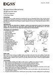
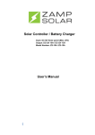
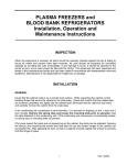
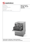
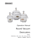
Basic
FAULT FINDING
Manual
Compiled by Craig Brown
INDEX
• Tools required
1
• 1st check on site
2
• Checking the gas
2
• Unit not cooling
3
• Unit not heating
3
• Water leak
4
• Compressor not starting
5
• Outdoor fan not starting
5
• Testing the capacitor
6
• Vacuuming and charging the system
6
• Checking for gas leaks
7
• Sizing a room for a unit
7
• What to prepare before you call for technical assistance
7
TOOLS REQUIRED
The air conditioning technician requires a number of specialized tools to carry out his job effectively. Among these
are the basic hand tools and ladders and so forth. There are also a number of items that are critical in the diagnosing
of faults on modern air conditioners. These are tools that you MUST carry if you hope to diagnose faults:
•
•
•
•
•
•
A good set of accurate gauges
A quality vacuum pump in good working order
A multi-meter including a clamp amp meter.
A capacitor tester if this function is not available on the multi-meter.
An accurate digital thermometer.
An accurate digital scale that can weigh in refrigerant to two decimal points 1
1ST CHECK ON SITE
When you arrive on site for the first time, there are a number of checks you need to carry out before you begin to try to
diagnose a problem. These may seem obvious, but it is easy to overlook something simple, and waste a lot of time looking
for a more complex fault than what actually exists. A few minutes spent checking the simple things can save hours and
plenty of money on something misdiagnosed.
•
•
•
•
•
•
•
•
Is the power supply to the unit on and correct (230VAC + or – 10% in the case of a single phase unit and 380 –
415 VAC in the case of a 3 phase system)?
Are the filters and indoor coil clean and free of obstruction?
Is the indoor unit barrel fan clean? This is very important as a dirty barrel fan causes a multitude of problems.
Are there any lights flashing or error codes displayed on the indoor unit or remote control?
Is the outdoor unit coil clean and free of obstructions? A bush or tree that has grown against the coil will
severely restrict airflow, cause high head pressure problems.
Does the outdoor fan look in good condition and unobstructed?
Do the interconnecting cables or pipes look damaged?
Are there obvious oily marks on the pipes/flare nuts/coil/unit casing? These could indicate a leak.
CHECKING GAS
Gas can only be accurately checked whilst the unit is running. Our
units use either R22 or R410a. You must ensure that you use R410a
gauges on an R410a unit. Using R22 gauges on an R410a system is
dangerous! A technician’s safety comes first! Checking the pressure on
a R22 unit is straight forward and easier to get an accurate reading. On
an inverter unit, it is more difficult, but possible to get a good idea of
the pressure in the system. Remember that the pressure in the system
is affected by the ambient temperature. On a cold day a unit’s pressure
will look lower than if you checked on a hot day.
R22:
R22 or R410A? Check the label first!
Heating pressure check: fit red hose while unit
running on cooling, then switch unit to heating
Cooling pressure check: blue hose fitted to suction port
With the unit on cooling, fit the blue hose (low pressure) to the unit’s suction port (the bigger of the two ports). Once the
outdoor unit has started up, the pressure should pull right down and slowly start climbing again. Once it has settled, the
pressure should be around 4.4bar / 440kPa / 60psi. While the unit is running in cooling, carefully remove the blue hose
avoiding refrigerant burns.
2
To test the pressure on heating, fit the red hose (high pressure) to the unit’s suction port whilst the unit is running on
cooling. This is because the pressure is lower at the suction port when the unit is on cooling than it is when the unit
is on heating. Switch the unit onto heating and wait for the unit to start. Once the unit starts, the pressure should start
climbing. Once the pressure reaches around 20bar/ 2000kPa / 295psi, you should notice a slight dip in the pressure;
this is the indoor fan motor starting up. There after the pressure will begin to climb again. Once it reaches around
26bar / 2600kPa / 390psi, the outdoor fan should cycle off or slow down depending on the model. The pressure
should now begin to drop. Once the pressure reaches about 17bar / 1700kPa / 260psi the outdoor fan should start up
again or speed up. If the unit is failing to reach a point where the outdoor fan motor cycles off, you could be short of
gas. If the unit is overshooting on pressure and the compressor is tripping out before the fan stops/slows, you could
be overcharged.
R 4 10 A
To get check the pressure in an R410a fixed speed compressor, follow the same procedures as with the R22 unit, but
the pressures will be different. On cooling you should be looking for around 8.2bar / 820kPa / 130psi. On heating, the
fan should cycle off at around 32bar / 3200kPa / 500psi.
On an R410a inverter unit, to test the pressure on cooling, set the unit to cooling on the lowest set temperature. Listen
to the outdoor unit as it starts up. You should hear the compressor ramping up. When it seems that the compressor
is running at its fastest speed, the pressure should be around 8.2bar / 820kPa / 130psi. This is a rough guide, as there
is no way of knowing the exact frequency of the compressor when you are checking the pressure. If the pressure is
significantly below this with the compressor running at what sounds like its highest speed, there is a good chance the
unit is short of refrigerant.
NB!!!
Treat refrigerant gas with the utmost respect. It has the potential to deliver a serious and painful injury. If you have a
leak on an R410a inverter system, recover the gas, repair the leak, pressure test with nitrogen to ensure the leaks are
repaired, vacuum the system to 1Torr / 1000 micron and weigh in the correct amount of refrigerant as specified on the
unit’s labels.
UNIT NOT COOLING
There are a number of issues that can cause a unit to stop cooling. A lack of refrigerant, a blockage or a lack of air
flow are the most common causes.
•
•
•
•
•
•
•
•
•
Are the filters clean?
Are the indoor and outdoor coils clean?
Is the gas pressure correct? An overcharge or undercharge can prevent effective cooling.
Is the airflow unhindered?
Is the indoor barrel fan clean?
Is there a section of indoor coil that is not the same temperature as the rest? If so, this could indicate a
blockage.
Are there any kinked pipes?
Is the compressor and outdoor fan running?
Are the amps within range? High amps can indicate overcharge or a blockage, low amps can indicate
bypassing on the reverse valve or a shortage of refrigerant.
U N I T N O T H E AT I N G
Solenoid valve: apply power and
test by touching with a screwdriver
– it should be magnetised
3
The issues that affect the heating performance of the unit are similar to those that affect the cooling. We are again checking
refrigerant charge, air flow and for signs of a blockage. Remember that the indoor unit will only start once the indoor coil
has reached temperature, so we are expecting the compressor to start before the indoor unit.
•
•
•
•
•
•
•
•
•
Are the filters clean?
Are the indoor and outdoor coils clean?
Is the gas pressure correct? An overcharge or undercharge can prevent effective heating.
Is the airflow unhindered?
Is the indoor barrel fan clean?
Is there a section of indoor coil that is not the same temperature as the rest? If so, this could indicate a blockage.
Are there any kinked pipes?
Is the compressor running?
Are the amps within range? High amps can indicate overcharge or a blockage, low amps can indicate bypassing
on the reverse valve or a shortage of refrigerant.
4way valve: 2 pipes should be hot and 1 cold.
•
•
•
•
If you feel that all of the pipes going into the 4way / reverse valve are the same temperature (hot) this normally
indicates that the reverse valve is faulty.
Check that the electrical terminal that supplies a power to the solenoid that controls the 4way / reverse valve. An
absence of power could indicate a damaged communication cable or faulty PC board.
Check that the solenoid valve is securely attached to the 4way / reverse valve.
To check if the solenoid is working, apply power to it and touch it with a steel screw driver, it should be
magnetised.
WA T E R L E A K
Water leaking from the indoor unit can be caused by several factors, including the unit freezing up, a blocked drain or
broken pipes/drain pans and the level of the drain or indoor unit.
•
•
•
•
•
•
•
•
•
Is the indoor unit level? If the unit is at an angle, the condensate water will leak from the unit before it can reach
the drain.
Is the drain running at a downwards angle? Any up-turn in the drain pipe can cause water to flood back to the
indoor unit.
Is the drain pipe blocked?
Check the drip tray and indoor unit back body for cracks. Water marks can indicate a crack too small to see with
the naked eye.
Is there sufficient air flow through the unit?
Is the barrel fan clean?
Is the gas pressure correct?
Is the unit sized correctly? An undersized unit can run until it eventually freezes up and then leaks.
Is the unit being run constantly for extended periods of time?
4
C O M P R E S S O R N O T S TA R T I N G
The compressor should come in when the indoor unit calls for either heating or cooling and it should cycle off
regularly. If the compressor is not starting or is tripping the power, there are a number of checks that need to be made.
T R I P P I N G T H E P OW E R
Firstly, if the compressor is tripping the power, we need to establish if it is tripping the earth leakage or if it is tripping
its own circuit breaker. If it is tripping the earth leakage, there is a chance that the compressor is down to earth.
If it is tripping its own circuit breaker, it could be that the compressor is seized, the capacitor is faulty or the circuit
breaker is too small / incorrect. Please use a curve 1 circuit breaker for the air conditioner’s power supply (this usually
has an orange switch). This circuit breaker allows for the start-up current of compressor without tripping. Remember
that the start-up current of the compressor is normally 4 to 6 times higher than the running current.
If you suspect that the compressor may be seized, this can be checked by first ensuring that the capacitor is within
range (See “capacitor testing” for the procedure). If the capacitor is within range and the compressor still trips its
circuit breaker or hums, you can use your clamp ammeter to check the current being drawn by the compressor as
it tries to start. If the current keeps climbing until the klixon /OLP trips, the compressor is seized and needs to be
replaced.
If the unit is tripping the earth leakage, the first thing that needs to be checked is that the compressor is not down to
earth. In order to do this, you can follow this procedure; first ensure that the power supply to the unit is off. The wires
need to be removed from the compressor terminals. Please pay careful attention to where they came off as if you put
them back in the wrong order, the compressor will not run. Once the wires are off, measure between the pins of the
compressor with your multi-meter set on ohms (Ω). There should be a resistance reading between each of the pins.
You can then measure each of the pins to an earth (you can use the red test lead on each of the compressor pins, one
at a time, and the black test lead to any copper pipe) you should not get a resistance reading here. The multi-meter
should display OL or ∞. If you get a reading with an ohm value, the compressor is down to earth and needs to be
replaced. It also means that the system needs to be flushed with flushing liquid and then vacuumed thoroughly and a
bi-direction burn out drier fitted to the suction line.
C O M P R E S S O R N O T S TA R T I N G
If the compressor is not starting, we need to determine where the interruption of power is occurring. The first point
to test is the live to the compressor from the PC board. The live to the compressor is the terminal labelled “1” on the
indoor and outdoor unit. If you measure from the neutral terminal to “1” and you are not getting 220VAC, the PC board
is not sending the signal for the compressor to start. This can be due to a PC board fault or possibly, a sensor error. If
you are getting power to “1” terminal on the indoor and outdoor units, the problem lies in the outdoor unit. If you are
getting 220VAC on the indoor terminal but not on the outdoor terminal, the fault lies with the communication cable.
Let us assume that we are working on a unit that the compressor is started with a contactor. We need to establish
if the contactor is pulling in. If it is pulling in and the compressor is still not starting, we need to check that we have
continuity through the contactor. If a point has been burnt on the contactor, even if it is pulled in, the compressor will
not start. If the contactor is not pulling in, we need to check the various safeties on the unit, an HP or LP switch or
discharge temperature sensor or other safety switch can keep the compressor from coming in. Normally the safeties
run in series on the neutral side of the contactor coil, so if even one safety is out, the contactor will not pull in. If you
have continuity on your neutral, and your live to the contactor is good, you should be able to measure 220VAC at the
connection points for the coil of the contactor. If you are measuring 220VAC and the contactor is still not pulling in, the
contactor is most likely faulty.
O U T D O O R FA N N O T S TA R T I N G
If the outdoor fan is not running when the unit is on cooling, the head pressure will climb and the unit will trip. Just
remember that in heating operation, there are times when the outdoor fan will not be running.
•
•
•
Is there an obstruction stopping the fan blade from turning?
Test on the fan terminals to neutral to see if there is 220VAC, if not the PC board is not giving the signal for the
outdoor fan to turn on.
Is the fan capacitor within its correct range?
5
TESTING THE CAPACITOR
The compressor’s capacitor is responsible for starting the compressor and the fan capacitor is responsible for starting
the fan. If either of these fails, their respective component will not start. In order to test these, you must first switch off
the power supply to the unit. Capacitors are measured in microfarads, the symbol for which is µƒ. In order to check
if a capacitor is working, first we need to check its µƒ rating on the side of the capacitor. We then remove the wires
on the capacitor, making sure to remember where they go in order to put them back correctly. Once the wires are off,
we short the pins together with a screw driver. Be careful not to shock yourself while shorting the capacitor out. The
pictures below are of a fan capacitor and a compressor capacitor respectively, you need to short from point “A” to
point “B”. The red ring indicates where the microfarad rating is displayed.
Fan Capacitor
Compressor Capacitor
To test the capacitor, we select the capacitor setting on the multi-meter. This is normally under resistance and is often
displayed as nf as the unit on the screen. Hold the test leads on “A” and “B”. It normally takes a few seconds to get
an accurate reading. Compare the reading you get to what is specified on the casing of the capacitor. If it is more than
10% under the rating, replace the capacitor.
VACUUMING AND CHARGING THE SYSTEM
When installing a unit or working on a unit with the internal or external pipe work open to the atmosphere, it is critical
that you vacuum the system once you are done. It is important that you use a good vacuum pump and that you replace
your vacuum pump’s oil regularly. Changing the oil in your vacuum pump is explained in the user manual, follow
these directions carefully. Checking your vacuum on your gauges is not enough, you need a vacuum gauge to check
that the vacuum you have pulled is sufficient to remove all the atmospheric moisture out of your system. There are
vacuum gauges of all shapes and sizes in a variety of price ranges. Choose an accurate one within your price range.
When pulling your vacuum, make sure you vacuum to at least 1000micron and make it holds this vacuum for at least
an hour. If the vacuum rises slowly, but stops before it reaches 3000micron, there is still moisture in the system. If it
keeps rising above 3000micron, there is a leak on the system. Do not rely solely on your vacuum pump for checking
for leaks. You also need to carry out proper positive pressure testing to ensure your system is leak free.
When charging R22 gas, bottle to be upright
When charging R410A gas, bottle to be upside down
6
Once you are happy that your system is leak free and well vacuumed, you can re-charge the system. The label on
the side of the outdoor unit will tell you exactly how much refrigerant you need to add. You can weigh in the correct
gas charge to the system to ensure that your system is perfectly charged. Remember that units must always be
charged while they are in the cooling mode. R22 units must be charged as vapour (the bottle upright) and R410a
units must be charged as liquid (the bottle upside down). It is critical to weigh in the correct amount. If an R410a
system loses more than 15% of its total charge, it needs to be recharged completely with virgin refrigerant. This is
because R410a is a blend and the ratio of the blend needs to be maintained. CHECKING FOR GAS LEAKS
It is of utmost importance that your system is gas tight. If you have a leak, the system will give endless problems
and you may end up losing the compressor and risk blocking the 4way/reverse valve. There are a number of ways
to find a leak on the system. Any place you find oil spots on the system, piping or arm flex is an indication that there
is a leak nearby. One can also make use of electronic leak detectors, or my favourite method, soap and glycerine. To
make a leak detection liquid, mix 1 part sunlight soap and 1 part glycerine into a container. Paint this mixture onto
any spots you suspect may be leaking. The pressure inside the system from the refrigerant or nitrogen will cause
this mixture to bubble any place it is leaking out. The leak can then be repaired and the system re-pressure tested
and finally vacuumed.
SIZING A ROOM FOR A UNIT
Please note that this section is a guideline, and factors not mentioned here can have a dramatic effect on heat load.
If you are unsure about what size air conditioner an area will require, please contact one of the sales representatives
at Fourways Air Conditioning to assist you.
The general rule for the Highveld region is 550BTUs per square meter of room size. Please remember to include any
passageways or open areas such as bathrooms leading off the space you require conditioned. Also high ceilinged
areas will require extra capacity. Remember that glass allows a lot of heat into a room and also allows just as much
heat to escape when you are in heating mode. Big windows will mean you need to upsize! Electric equipment and
people also add significant heat load to a room. If unsure, contact a sales representative.
Remember when quoting that an R22 unit requires at least 1.5m of piping between the indoor and outdoor to
reduce noise and pressure, an R410a unit requires at least 2.5m of piping between the indoor and the outdoor for
the same reason.
WHAT TO PREPARE BEFORE YOU CALL FOR
TECHNICAL ADVICE:
Sometimes after checking everything you can, you still cannot get the unit right. If this is the case, there are
technical advisors employed by Fourways Air Conditioning that will be happy to assist you over the phone. If they
cannot help you solve the problem over the phone, they may arrange to visit your site with you to assist you with
rectifying your problem.
When you call please have the following information at hand:
•
•
•
The model number of the indoor unit.
The error code that the unit is displaying on the indoor unit, outdoor unit and remote.
As much history of the unit as possible (what previous repairs have been done, spares changed etc.).
Gauteng & Central region
Fourways Airconditioning (Jhb)
(011) 704-6320
Pretoria
W. & N. Cape
E. Cape
Fourways Airconditioning (Pta) Samair (Cape Town) Samair (Port Elizabeth)
(012) 643-0445
(021) 556-8292
(041) 484-6413
Kwa-Zulu Natal
Fourways Airconditioning (KZN)
(031) 579-1895