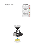
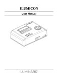
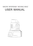
1
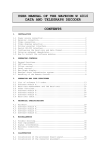
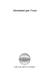
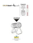
Snapshot Use on Dimmer Outdoor Sound Activated DMX Master/Slave Autoswitching Power Supply Replaceable Fuse User Serviceable Duty Cycle User Manual 3000 N 29th Ct, Hollywood, FL 33020 U.S.A. (800) 762-1084 – (954) 929-1115 FAX (954) 929-5560 www.chauvetlighting.com TABLE OF CONTENTS 1. Before You Begin ...................................................................................................................................... 3 WHAT IS INCLUDED ..................................................................................................................................................................................... 3 UNPACKING INSTRUCTIONS ......................................................................................................................................................................... 3 MANUAL CONVENTIONS .............................................................................................................................................................................. 3 ICONS ....................................................................................................................................................................................................... 3 SAFETY INSTRUCTIONS ............................................................................................................................................................................... 4 LED EXPECTED LIFESPAN .......................................................................................................................................................................... 4 2. Introduction ............................................................................................................................................... 5 FEATURES ................................................................................................................................................................................................. 5 Additional Features ................................................................................................................................................... 5 Options ..................................................................................................................................................................... 5 DMX CHANNEL SUMMARY .......................................................................................................................................................................... 6 Product Overview...................................................................................................................................................... 7 3. SETUP ........................................................................................................................................................ 8 AC POWER ............................................................................................................................................................................................... 8 MOUNTING ................................................................................................................................................................................................ 9 Orientation ................................................................................................................................................................ 9 Rigging ..................................................................................................................................................................... 9 FIXTURE LINKING ..................................................................................................................................................................................... 10 Data Cabling ........................................................................................................................................................... 10 DMX Data Cable ..................................................................................................................................................... 10 Cable Connectors ................................................................................................................................................... 10 3-Pin to 5-Pin Conversion Chart .............................................................................................................................. 11 Setting up a DMX Serial Data Link .......................................................................................................................... 11 MASTER/SLAVE FIXTURE LINKING.............................................................................................................................................................. 11 4. Operating Instructions.............................................................................................................................12 CONTROL OPTIONS .................................................................................................................................................................................. 12 DMX control without ID address .............................................................................................................................. 12 DMX addressing with ID address ............................................................................................................................ 12 Setting the Starting DMX address ........................................................................................................................... 13 CONTROL PANEL FUNCTIONS .................................................................................................................................................................... 13 Password Menu Lockout ......................................................................................................................................... 13 Upload Customs ..................................................................................................................................................... 13 Menu Map............................................................................................................................................................... 14 DMX CHANNEL VALUES ........................................................................................................................................................................... 16 STAGE 1 ................................................................................................................................................................ 16 BLOCK ................................................................................................................................................................... 18 ARC1 ARC1+D ............................................................................................................................................. 18 ARC2 ARC2+D ............................................................................................................................................. 18 IMPORTANT NOTES ABOUT STAGE 1 DMX OPERATION ............................................................................................................................. 19 CONTACT US ........................................................................................................................................................................................... 19 5. Appendix...................................................................................................................................................20 DMX PRIMER .......................................................................................................................................................................................... 20 GENERAL MAINTENANCE .......................................................................................................................................................................... 21 RETURNS PROCEDURE ............................................................................................................................................................................. 21 CLAIMS ................................................................................................................................................................................................... 21 PHOTOMETRIC DATA ................................................................................................................................................................................ 22 COLORDASH™ BLOCK SERVICE MAINTENANCE GUIDE ............................................................................................................................. 23 EXPLODED VIEW ...................................................................................................................................................................................... 24 WIRING DIAGRAM ..................................................................................................................................................................................... 25 TECHNICAL SPECIFICATIONS ..................................................................................................................................................................... 26 COLORdash™ Block User Manual 2 6/19/2009 4:54 PM 1. BEFORE YOU BEGIN What is included 1 x COLORdash™ Block 1 x Power cable with plug 1 x 6.6 ft (2 m) power linking cable 1 x Safety eyebolt 1 x Warranty Card 1 x User Manual Unpacking Instructions Immediately upon receiving a fixture, carefully unpack the carton, check the contents to ensure that all parts are present, and have been received in good condition. Notify the shipper immediately and retain packing material for inspection if any parts appear damaged from shipping or if the carton itself shows signs of mishandling. Save the carton and all packing materials. In the event that a fixture must be returned to the factory, it is important that the fixture be returned in the original factory box and packing. Manual Conventions This manual uses the following conventions to differentiate certain types of information from the regular text. MEANING CONVENTION A DIP switch to be configured. [10] <Menu> A key to be pressed on the fixture’s control panel 1 ~ 512 A range of values Settings An option shown on the display not to be modified (for example, showing the operating mode/current status) MENU > Settings A sequence of menu options to be selected A value to be entered or selected ON “Appendix” A section of the manual Icons This manual uses the following icons to indicate information that requires special attention on the part of the user. MEANING ICONS This paragraph contains critical installation, configuration or operation information. Failure to comply with this information may render the fixture partially or completely inoperative, cause damage to the fixture or cause harm to the user or technician. This paragraph contains important installation or configuration information. Failure to comply with this information may prevent the fixture from functioning correctly. This paragraph reminds you of useful, although not critical, information. COLORdash™ Block User Manual 3 6/19/2009 4:54 PM Safety Instructions Please read these instructions carefully because they include important information about the installation, usage and maintenance of this product. There are no user serviceable parts inside the unit. Any reference to servicing the unit you may find from now on will only apply to properly certified technicians. Do not open the housing or attempt any repairs unless you are one of them. In the unlikely event that your unit may require service, please contact CHAUVET at (954) 929-1115. Keep this Manual for future consultation. If you sell the unit to another user, make sure that they also receive this Manual. Always make sure that you are connecting the unit to the proper voltage, as per the specifications. Always disconnect from power source before servicing or replacing fuse and be sure to replace with same fuse type. This product is for indoor use only! To prevent risk of fire or shock, do not expose fixture to rain or moisture. Secure fixture to fastening device using a safety chain. Maximum ambient temperature (Ta) is 104° F (40° C). Do not operate the fixture at temperatures higher than this. In the event of a serious operating problem, stop using the unit immediately! Never connect the device to a dimmer pack. Make sure the power cord is never crimped or damaged. Never disconnect the power cord by pulling or tugging on the cord. Avoid direct eye exposure to the light source while it is on. Do not daisy chain power to more than 20 units @ 120 V or 30 units @ 230 V. Please refer to all applicable local codes and regulations for proper installation of this fixture. LED Expected Lifespan LEDs gradually decline in brightness over time. HEAT is the dominant factor that leads to the acceleration of this decline. Packaged in clusters, LEDs exhibit higher operating temperatures than in ideal or singular optimum conditions. For this reason when all color LEDs are used at their fullest intensity, life of the LEDs is significantly reduced. It is estimated that a viable lifespan of 40,000 to 50,000 hours will be achieved under normal operational conditions. If improving on this lifespan expectancy is of a higher priority, place care in providing for lower operational temperatures. This may include climatic-environmental and the reduction of overall projection intensity. COLORdash™ Block User Manual 4 6/19/2009 4:54 PM 2. INTRODUCTION Features 3, 4, 5, 9, 11 or 12-channel DMX LED wash light (with ID addressing) Operating modes 3-channel: RGB control 4-channel: RGB, dimmer 4-channel: RGB+W control 5-channel: RGB+W, dimmer 11-channel: RGB+W, ID, dim, strobe, macro, fan control, automatic, custom 12-channel: RGB for individual block control Blackout/static/dimmer/strobe/pulse RGB+W color mixing with or without DMX controller Built-in automated programs via master/slave Recall custom programs via master/slave or DMX Adjustable fan speeds Additional Features High-power, 1 W (350 mA) LEDs Additional power output: (IEC) max 20 units @ 120 V or 30 units @ 230 V LCD display with password protection Control independent or multiple combinations of the LED modules/clusters Transfer custom programs between fixtures Double-bracket yoke that doubles as floor stand Options 33 ft (10 m) power extension cable (EXT-2) COLORdash™ Block User Manual 5 6/19/2009 4:54 PM DMX Channel Summary The COLORdash™ Block has six DMX channel configurations. These are referred to as “Personalities” in this manual and in the fixture onboard control panel. The six personalities are: STAGE 1, BLOCK, ARC 1, ARC 1 + D, ARC 2, ARC 2 + D. Each of the different personalities can be accessed from the control panel. Please see section on “Control Panel Functions” for a description on how to access these. [STAGE 1] [ARC 1] [ARC2] CHANNEL DESCRIPTION [BLOCK] CHANNEL DESCRIPTION 1 Dimmer 1 Block 1 - Red 2 Red 2 Block 1 - Green 3 Green 3 Block 1 - Blue 4 Blue 4 Block 2 - Red 5 White 5 Block 2 - Green 6 Color Macro 6 Block 2 - Blue 7 Strobe 7 Block 3 - Red 8 Auto & Custom Programs 8 Block 3 - Green 9 Auto Speed Adjustment 9 Block 3 - Blue 10 ID Address Selection 10 Block 4 - Red 11 Block Selection 11 Block 4 - Green 12 Block 4 - Blue CHANNEL DESCRIPTION [ARC1+D] CHANNEL DESCRIPTION 1 Red 1 Dimmer 2 Green 2 Red 3 Blue 3 Green 4 Blue CHANNEL DESCRIPTION [ARC 2+D] CHANNEL DESCRIPTION 1 Red 1 Dimmer 2 Green 2 Red 3 Blue 3 Green White 4 Blue 5 White 4 COLORdash™ Block User Manual 6 6/19/2009 4:54 PM Product Overview Control Panel Length Height Power Link Out Power Out Width Power In DMX Out Bracket Adjustment Knob COLORdash™ Block User Manual 7 DMX In 6/19/2009 4:54 PM 3. SETUP AC Power This fixture has an auto-switching power supply that can accommodate a wide range of input voltages (100 ~ 240 VAC, 50/60 Hz). Before powering on the unit, make sure the line voltage to which you are connecting it is within the range of accepted voltages. This fixture is designed for power linking from one COLORdash™ Block to another COLORdash™ Block fixture. This is done with IEC extension cables. Always connect the fixture to a switched circuit. Never connect the fixture to a rheostat (variable resistor) or dimmer circuit, even if the rheostat or dimmer channel is used only as a 0 to 100% switch. To determine the power requirements for a particular fixture, see the label affixed to the back plate of the fixture or refer to the fixture’s specifications chart. A fixture’s listed current rating indicates its average current draw under normal conditions. Always connect the fixture to a circuit with a suitable electrical ground. COLORdash™ Block User Manual 8 6/19/2009 4:54 PM Mounting Orientation This fixture may be mounted in any safe position, provided there is adequate room for ventilation. Rigging The fixture includes a mounting yoke to which a rigging clamp can be attached. You must supply your own clamp and make sure the clamp is capable of supporting the weight of this fixture. You can order “C” and “O” clamps from any CHAUVET dealer or distributor (CLP-15, CLP-06 recommended). If you are using this fixture for down lighting, you must use at least one safety cable/chain for each fixture in addition to the double-bracket yoke. If hanging the fixture for overhead use, please follow the below steps: 1) Block access below the work area and use a suitable and stable platform when installing or servicing fixture. 2) Always use safety cables. The safety cable must be capable of holding 10 times the weight of the fixture. 3) Verify that the structure can hold 10 times the weight of all to-be installed fixtures. Double-bracket yoke Hanging Clamp Blocks 1-4 The hanging clamp is sold separately COLORdash™ Block User Manual 9 6/19/2009 4:54 PM Fixture Linking You will need a serial data link to run light shows of one or more fixtures using a DMX controller or to run synchronized shows on two or more fixtures set to a master/slave operating mode. The combined number of channels required by all the fixtures on a serial data link determines the number of fixtures the data link can support. The fixtures must be linked using DMX cable in a daisy chain (serial) fashion. To comply with the EIA-485 standard, no more than 32 fixtures should be connected on one daisy chain without using a DMX optically-isolated splitter. Doing otherwise may result in deterioration of the digital DMX signal. USITT recommends limiting the total length of the DMX cable (from the first fixture/controller to the last fixture) to 300 ~ 455 m (985 ~ 1,500 ft). Data Cabling To link fixtures together you must obtain data cables. You can purchase CHAUVET certified DMX cables directly from a dealer/distributor or construct your own cable. If you choose to create your own cable, please use data-grade cables that can carry a high quality signal and are less prone to electromagnetic interference. DMX Data Cable Use a Belden© 9841 or equivalent cable which meets the specifications for EIA RS-485 applications. Standard microphone cables cannot transmit DMX data reliably over long distances. The cable must have the following characteristics: Type: shielded, 2-conductor twisted pair Maximum capacitance between conductors: 30 pF/ft Maximum capacitance between conductor and shield: 55 pF/ft Maximum resistance: 20 ohms/1000 ft Nominal impedance: 100 – 140 ohms Cable Connectors The cable must have a male XLR connector on one end and a female XLR connector on the other end. DMX connector configuration 1 3 2 COMMON INPUT 1 3 2 DMX + DMX - 1 3 2 OUTPUT 120 ohm, ¼ W resistor between pin 2 (DMX -) and pin 3 (DMX +) on the output of the last fixture. To avoid signal transmission problems and interference, it is always advisable to connect a DMX signal terminator. Do not allow contact between the common and the fixture’s chassis ground. Grounding the common can cause a ground loop, and your fixture may perform erratically. Test cables with an ohmmeter to verify correct polarity, and to make sure the pins are not grounded or shorted to the shield or each other. COLORdash™ Block User Manual 10 6/19/2009 4:54 PM 3-Pin to 5-Pin Conversion Chart If you use a controller with a 5-pin DMX output connector, you will need to use a 5-pin to 3-pin adapter. CHAUVET Model No: DMX5M, or DMX5F. The chart below details a proper cable conversion: 3-PIN TO 5-PIN CONVERSION CHART Conductor 3-Pin Female (Output) 5-Pin Male (Input) Ground/Shield Pin 1 Pin 1 Data ( - ) signal Pin 2 Pin 2 Data ( + ) signal Pin 3 Pin 3 Not used Pin 4 Not used Pin 5 Setting up a DMX Serial Data Link Universal DMX Controller 1. Connect the (male) 3-pin connector side of the DMX cable to the output (female) 3-pin connector of the controller. 2. Connect the end of the cable coming from the controller which will have a (female) 3-pin connector to the input connector of the next fixture consisting of a (male) 3-pin connector. 3. Then, proceed to connect from the output as stated above to the input of the following fixture and so on. This drawing provides a general illustration of the DMX input/output panel of a lighting fixture. CHAUVET Certified DMX Data Cables Order Code Description DMX1.5 DMX Cable 1.5 m/4.9 ft DMX4.5 DMX Cable 4.5 m/14.8 ft DMX10 DMX Cable 10 m/32.8 ft Continue the link Master/Slave Fixture Linking 1. Connect the (male) 3-pin connector side of the DMX cable to the output (female) 3-pin connector of the first fixture. 2. Connect the end of the cable coming from the first fixture which will have a (female) 3-pin connector to the input connector of the next fixture consisting of a (male) 3-pin connector. Then, proceed to connect from the output as stated above to the input of the following fixture and so on. Often, the setup for Master-Slave and Standalone operation requires that the first fixture in the chain be initialized for this purpose via settings in the control panel. Secondly, the fixtures that follow may also require a slave setting. Please consult the “Operating Instructions” section in this manual for complete instructions for this type of setup and configuration. COLORdash™ Block User Manual Slave 11 Slave Master 6/19/2009 4:54 PM 4. OPERATING INSTRUCTIONS Control Options The COLORdash™ Block is addressable in the DMX range of 001 to 512. In its simplest control form, this allows for the control of up to 46 fixtures in the 11-channel Stage 1 personality; however, a secondary ID address system exists for use in a limited DMX universe and architectural environments. The ID address system allows the user to assign up to 66 fixtures within the same DMX address; in effect, multiplying the control of COLORdash™ Block within a single universe to 3,036 fixtures. The COLORdash™ Block ID address system is accessed using DMX channel 10 (Stage 1). Consideration must be placed when programming live performances or cues that need to trigger on demand or on a time line. So, to remain within one-second execution time, program no greater than 10 fixtures on ID addressing per DMX channel. DMX control without ID address The COLORdash™ Block operates on 12 channels of DMX (STAGE 1). Address each fixture in increments of 11 channels. (for example: 1, 12, 23, 34, 45, etc.) To save time you can use the same DMX address for each fixture. All fixtures will then respond simultaneously to control. You may also group your fixtures and address those groups alike for faster programming and control. 1. Access the control panel function by pressing <MENU> until the RUN is displayed. 2. Press <ENTER> and use the <UP/DOWN> to select DMX function. 3. Then, Press <MENU> until ADDRESS is displayed. 4. Pres <ENTER>. 6. Use <UP/DOWN> to increase or decrease channels between 001 and 512. 7. Press <ENTER> to confirm action. Then press <MENU> to exit. Deactivate ID addressing in each fixture by setting panel function ID ON/OFF to OFF. MENU>SETTINGS>ID ON/OFF>OFF If ID addressing is not deactivated in the fixture’s control panel function, unintended results may occur if values are present in channel 10. Make sure values on channel 10 are set to 0. DMX addressing with ID address 1. Follow instructions 1 ~ 7 in the previous section for DMX addressing. 2. Activate ID addressing in each fixture by setting panel function ID ON/OFF to ON. MENU>Settings>ID ON/OFF>ON] 3. For every DMX starting address the user can set 66 separate ID addresses. 4. Set ID addresses in each fixture by setting panel function ID address to incremental values. (for example: 1, 2, 3, 4, 5, 6, etc.). MENU>Settings>ID address>01~66 5. ID addresses are accessible using channel 10 (Stage 1). DMX Address: 001 ID Address: 01 Universal DMX Controller COLORdash™ Block User Manual DMX Address: 001 ID Address: 02 DMX Address: 001 ID Address: 03 DMX Address: 013 ID Address: 01 DMX Address: 013 ID Address: 02 DMX Address: 013 ID Address: 03 The figure above shows a simple DMX layout which has used three units at each DMX address. The three units have different ID addresses which allows the user to collectively control the whole group of units at that DMX address by setting channel 10 to 0, or to control each unit independently by first selecting the DMX address and then by using channel 10 to locate the target ID address. 12 6/19/2009 4:54 PM Setting the Starting DMX address Each fixture requires a starting address from 1 through 512. A fixture requiring one or more channels for control begins to read the data on the channel indicated by the starting address. For example, a fixture that occupies or uses seven channels of DMX and is addressed to start on DMX channel 100, will read data from channels: 100, 101, 102, 103, 104, 105 and 106. Choose starting addresses so that the channels used do not overlap. In addition, you should note the starting address selected for future reference. The COLORdash™ Block uses up to 12 channels of DMX (BLOCK). If this is your first time using DMX, we recommend reading the “DMX Primer” in the “Appendix” section. Control Panel Functions All fixture functions and settings are accessible via the built-in control panel interface. MENU ENTER UP BUTTON FUNCTION MENU Exits from the current menu or function ENTER UP DOWN DOWN Enables the currently displayed menu or sets the currently selected value in to the selected function Navigates upwards through the menu list and increases the numeric value when in a function Navigates downwards through the menu list and decreases the numeric value when in a function Password Menu Lockout The COLORdash™ Block has a password lock-out feature. Enable/disable this by using the Control Panel. This feature uses a default, non-changeable, password of <UP>, <DOWN>, <UP>, <DOWN>. After 30 seconds of inactivity, the lockout will automatically engage once it has been enabled. Upload Customs The custom programs in the COLORdash™ Block may be transferred (copied) from one fixture to another, thus giving the ability to have to only program them on a single fixture, and then duplicate this on several others. This is referenced in the control panel as Upload. Follow the steps below for this process. On all fixtures that are going to receive the upload, set them on SLAVE operation. 1. 2. 3. 4. 5. 6. 7. Disconnect from DMX controller. Using DMX cables, daisy chain the slave fixtures from the output of the fixture with the custom program to be copied to the other fixtures. Press <MENU>. Use <UP/DOWN> to select Settings in the control panel and press <ENTER>. Use <UP/DOWN> to select Upload Customs. Press <ENTER>. Use <UP/DOWN> to input the password. The customs portion of the screen will begin to flash. Press <ENTER> to confirm and begin the transfer. Uploading Customs will display. The slave fixtures will display green if the transfer is successful. They will display red if the transfer The units receiving the new custom programs from the master must be set to “SLAVE”. Otherwise, they will not allow receipt of the programs. COLORdash™ Block User Manual 13 6/19/2009 4:54 PM Menu Map MAIN FUNCTION SUB-FUNCTION Red Green 1. STATIC (Static Color) Blue White SELECTION 000 ~ 255* (0 ~ 100%) *Strobe range is 0~20 Hz INSTRUCTION User can combine Red, Green, Blue and White to generate a custom color Select strobing frequency between 0 and 20 Hz Strobe 3. ADDRESS 001 ~ 512 4. RUN DMX/Slave 5. PERSON (Personality) Stage 1 Block Arc1 Arc1+D Arc2 Arc2+D Choose from 10 automatic programs Choose from 10 programs that be customized under the “edit custom” menu option Sets the DMX starting address Sets the operating mode for the fixture: to receive signal from a DMX controller (DMX) or to receive signal from the DMX out of another fixture 11-channel RGBW+DMS, ID 12-channel RGB for each block (1 of 4) 3-channel RGB 4-channel RGB+D 4-channel RGBW 5-channel RGBW+D 6. ID (ID Address) 0~66 Assigns the ID address to a fixture 2. AUTO Auto (1~10) Custom (1~10) ID 7. SETTINGS Reset to factory? Upload custom? 8. PASSWORD Custom (1~10) 9. EDIT (Edit Custom) -(Scene 01-30) 10. FANS On/Off Turns ID addressing on or off Resets the fixture to the default, factory (Password required) settings Uploads a fixture’s custom program to (Password required) another fixture (same fixture only) Turns the password on or off (after 30 s of no activity, the control panel will turn On/Off on after selecting On) Red User can combine Red, Green, Blue and Green White to generate a custom color Blue (0~255) White Strobe Select strobing frequency (0 ~ 20 Hz) Time (0~255) Fade (0~255) AUTO Fan speed controlled automatically HIGH Fan speed at its maximum NORMAL Fan speed at its median LOW Fan speed at its lowest/most quiet OFF Fan off When the fan speed is at normal, low, or off the fixture will automatically override the speed as a protection, if the temperature becomes too hot. The default factory password is <UP>, <DOWN>, <UP>, <DOWN>. COLORdash™ Block User Manual 14 6/19/2009 4:54 PM COLORdash™ Block User Manual 15 6/19/2009 4:54 PM DMX Channel Values The COLORdash™ Block has six DMX channel configurations: STAGE 1, BLOCK, ARC 1, ARC 1 + D, ARC 2, and ARC 2 + D. STAGE 1 CHANNEL VALUE FUNCTION 4 000 255 5 000 255 6 000 010 011 035 036 060 061 085 086 110 111 135 136 160 161 185 186 210 211 215 216 220 221 225 226 230 231 235 236 240 241 245 246 250 251 255 7 000 004 005 255 8 000 010 011 020 021 030 031 040 041 050 051 060 061 070 071 080 081 090 091 100 101 110 111 120 121 130 131 140 141 150 151 160 161 170 171 180 181 190 191 200 201 210 211 220 221 230 231 240 241 250 251 255 Dimmer 0 100% Red (or STEP TIME when CUS.01-10 in CH.8 is activated) 0 100% Green (or FADE TIME when CUS.01-10 in CH.8 is activated) 0 100% Blue 0 100% White 0 100% Color Macro + White Balance No Function Red 100%/ Green Up/ Blue 0% Red Down/ Green 100%/ Blue 0% Red 0%/ Green 100%/ Blue Up Red 0%/ Green Down/Blue 100% Red Up/ Green 0%/Blue 100% Red 100%/ Green 0%/ Blue Down Red 100%/ Green Up/ Blue Up Red Down/ Green Down/ Blue 100% White 1: 3200 K White 2: 3400 K White 3: 4200 K White 4: 4900 K White 5: 5600 K White 6: 5900 K White 7: 6500 K White 8: 7200 K White 9: 8500 K Strobe No Function 0 20 Hz Fans, Auto + Custom Programs Set to display fan setting Fans OFF (hold channel value for 5 seconds) Fans LOW (hold channel value for 5 seconds) Fans NORMAL (hold channel value for 5 seconds) Fans HIGH (hold channel value for 5 seconds) Fans AUTO (hold channel value for 5 seconds) Auto 1 Auto 2 Auto 3 Auto 4 Auto 5 Auto 6 Auto 7 Auto 8 Auto 9 Auto 10 Custom 1 Custom 2 Custom 3 Custom 4 Custom 5 Custom 6 Custom 7 Custom 8 Custom 9 Custom 10 9 000 255 Auto Speed (only when CH.7 is between 061 ~ 255) 1 000 255 2 000 255 3 000 255 COLORdash™ Block User Manual 16 6/19/2009 4:54 PM STAGE 1 (Cont.) CHANNEL 9 CHANNEL 11 ID ADDRESSING VALUE ID VALUE ID VALUE ID 000 009 010 019 020 029 030 039 040 049 050 059 060 069 070 079 080 089 090 099 100 109 110 119 120 129 130 139 140 149 150 159 160 169 170 179 180 189 190 199 200 209 210 211 All IDs ID 1 ID 2 ID 3 ID 4 ID 5 ID 6 ID 7 ID 8 ID 9 ID 10 ID 11 ID 12 ID 13 ID 14 ID 15 ID 16 ID 17 ID 18 ID 19 ID 20 ID 21 ID 22 212 213 214 215 216 217 218 219 220 221 222 223 224 225 226 227 228 229 230 231 232 233 234 ID 23 ID 24 ID 25 ID 26 ID 27 ID 28 ID 29 ID 30 ID 31 ID 32 ID 33 ID 34 ID 35 ID 36 ID 37 ID 38 ID 39 ID 40 ID 41 ID 42 ID 43 ID 44 ID 45 235 236 237 238 239 240 241 242 243 244 245 246 247 248 249 250 251 252 253 254 255 ID 46 ID 47 ID 48 ID 49 ID 50 ID 51 ID 52 ID 53 ID 54 ID 55 ID 56 ID 57 ID 58 ID 59 ID 60 ID 61 ID 62 ID 63 ID 64 ID 65 ID 66 VALUE 000 010 011 021 022 032 033 043 044 054 055 065 066 076 077 087 088 098 099 109 110 120 121 131 132 142 143 153 154 164 165 175 176 186 187 197 198 208 209 219 220 230 231 241 242 255 COLORdash™ Block User Manual FUNCTION Block Block 1, Block 2, Block 3, Block 4 Block 1 Block 2 Block 3 Block 4 Block 3, Block 4 Block 1, Block 2 Block 2, Block 3 Block 3, Block 4 Block 4 Block 1, Block 2, Block 3 Block 2, Block 3, Block 4 Block 3, Block 4 Block 1 Block 2, Block 4 Block 1, Block 3 Block 2 Block 1, Block 3 Block 1, Block 2, Block 4 Block 1, Block 2 Block 4 Block 2, Block 3, Block 4 Block 1, Block 2, Block 3, Block 4 17 6/19/2009 4:54 PM BLOCK CHANNEL VALUE 1 000 255 2 000 255 3 000 255 4 000 255 5 000 255 6 000 255 FUNCTION Block 1 Red 0 100% Block 1 Green 0 100% Block 1 Blue 0 100% Block 2 Red 0 100% Block 2 Green 0 100% Block 2 Blue 0 100% CHANNEL VALUE 7 000 255 8 000 255 9 000 255 10 000 255 11 000 255 12 000 255 ARC1 FUNCTION Block 3 Red 0 100% Block 3 Green 0 100% Block 3 Blue 0 100% Block 4 Red 0 100% Block 4 Green 0 100% Block 4 Blue 0 100% ARC1+D CHANNEL 1 2 3 VALUE FUNCTION CHANNEL Red 000 255 0 100% Green 000 255 0 100% Blue 000 255 0 100% ARC2 VALUE FUNCTION 1 000 255 2 000 255 3 000 255 4 000 255 Dimmer 0 100% Red 0 100% Green 0 100% Blue 0 100% VALUE FUNCTION ARC2+D CHANNEL 1 2 3 4 VALUE FUNCTION CHANNEL Red 000 255 0 100% Green 000 255 0 100% Blue 000 255 0 100% White 000 255 0 100% 1 2 3 4 5 COLORdash™ Block User Manual 18 Dimmer 000 255 0 100% Red 000 255 0 100% Green 000 255 0 100% Blue 000 255 0 100% White 000 255 0 100% 6/19/2009 4:54 PM Important Notes about STAGE 1 DMX Operation Master Dimmer Channel 1 controls the intensity of the currently projected color When the slider is at the highest position (255), then the intensity of the output is at the maximum. Red, Green Blue and White Color Selection Channels 2, 3, 4 and 5 control the intensity ratio of each of the Red, Green, Blue, & White LEDs. Channels 2, 3, 4 and 5 can be combined together to create over 42 billion color combinations. Strobe Channel 7 controls the strobe of Channels 2 through 5. Channel 7 has priority over Channels 2, 3, 4, & 5. Speed of the strobe is adjustable from 0 ~ 20 Hz. Color Macros Channel 6 selects the required Color Macro. Channel 6 has priority over Channels 2, 3, 4, & 5. Channel 1 is used to control the intensity of the current Color Macro. ID Address Selection Use channel 10 to select the target ID address. Each independent DMX address can have up to 66 ID addressed fixtures. ID address 0 allows control of all fixtures simultaneously. Auto & Custom Programs Channel 8 selects the preset Auto/Custom programs 1~10 When activating the Auto/Custom programs, it is then possible to control the Step time and Fade time by using Channels 2 & 3, respectively. Contact Us World Wide General Information Chauvet Lighting 3000 North 29th Court Hollywood, FL 33020 voice: 954.929.1115 fax: 954.929.5560 toll free: 800.762.1084 Technical Support www.chauvetlighting.com voice: (954) 929-1115 - (Press 4) fax: (954) 929-5560 - (Attention: Service) World Wide Web www.chauvetlighting.com COLORdash™ Block User Manual 19 6/19/2009 4:54 PM 5. APPENDIX DMX Primer There are 512 channels in a DMX connection. Channels may be assigned in any manner. A fixture capable of receiving DMX will require one or a number of sequential channels. The user must assign a starting address on the fixture that indicates the first channel reserved in the controller. There are many different types of DMX controllable fixtures and they all may vary in the total number of channels required. Choosing a start address should be planned in advance. Channels should never overlap. If they do, this will result in erratic operation of the fixtures whose starting address is set incorrectly. You can however, control multiple fixtures of the same type using the same starting address as long as the intended result is that of unison movement or operation. In other words, the fixtures will be slaved together and all respond exactly the same. DMX fixtures are designed to receive data through a serial Daisy Chain. A Daisy Chain connection is where the DATA OUT of one fixture connects to the DATA IN of the next fixture. The order in which the fixtures are connected is not important and has no effect on how a controller communicates to each fixture. Use an order that provides for the easiest and most direct cabling. Connect fixtures using shielded two conductor twisted pair cable with three pin XLR male to female connectors. The shield connection is pin 1, while pin 2 is Data Negative (S-) and pin 3 is Data positive (S+). CHAUVET carries 3-pin XLR DMX compliant cables, DMX-10 (33’), DMX-4.5 (15’) and DMX-1.5 (5’) COLORdash™ Block User Manual 20 6/19/2009 4:54 PM General Maintenance To maintain optimum performance and minimize wear fixtures should be cleaned frequently. Usage and environment are contributing factors in determining frequency. As a general rule, fixtures should be cleaned at least twice a month. Dust build up reduces light output performance and can cause overheating. This can lead to reduced LED life and increased mechanical wear. Be sure to power off fixture before conducting maintenance. Unplug fixture from power. Use a vacuum or air compressor and a soft brush to remove dust collected on external vents and internal components; be sure to prevent the fans from turning during this process, as it can cause damage to the fans. Clean all glass when the fixture is cold with a mild solution of glass cleaner or Isopropyl Alcohol and a soft lint free cotton cloth or lens tissue. Apply solution to the cloth or tissue and drag dirt and grime to the outside of the lens. Gently polish optical surfaces until they are free of haze and lint. The cleaning of external optical lenses must be carried out periodically to optimize light output. Cleaning frequency depends on the environment in which the fixture operates: damp, smoky or particularly dirty surrounding can cause greater accumulation of dirt on the unit’s optics. Clean with soft cloth using normal glass cleaning fluid. Always dry the parts carefully. Clean the external optics at least every 20 days. Returns Procedure Returned merchandise must be sent prepaid and in the original packing; call tags will not be issued. Package must be clearly labeled with a Return Merchandize Authorization Number (RMA #). Products returned without the RMA # will be refused. Call CHAUVET and request an RMA # prior to shipping the fixture. Be prepared to provide the model number, serial number and a brief description of the cause for the return. Be sure to pack fixture properly; any shipping damage resulting from inadequate packaging is the customer’s responsibility. As a suggestion, proper UPS packing or double-boxing is always a safe method to use. CHAUVET reserves the right to use its own discretion to repair or replace product(s). Note: If you are given an RMA #, please include the following information on a piece of paper inside the box: 1) Your name 2) Your address 3) Your phone number 4) The RMA # 5) A brief description of the symptoms Claims Damage incurred in shipping is the responsibility of the shipper; therefore the damage must be reported to the carrier upon receipt of merchandise. It is the customer's responsibility to notify and submit claims with the shipper in the event that a fixture is damaged due to shipping. Any other claim for items such as missing component/part, damage not related to shipping, and concealed damage, must be made within seven (7) days of receiving merchandise. COLORdash™ Block User Manual 21 6/19/2009 4:54 PM Photometric Data COLORdash™ Block User Manual 22 6/19/2009 4:54 PM COLORdash™ Block Service Maintenance Guide SYMPTOM POSSIBLE CAUSE(S) POSSIBLE ACTION(S) General low light intensity Dirty lens assembly Clean the fixture regularly. Misaligned lens assembly Install lens assembly properly. White LED does not illuminate Faulty LED Replace the LED PCB (Part#: P222-CDBLED). Faulty LED driver Replace the LED Driver PCB (Part # P172-CDBDRV). Opened LED. If any red, green or blue LED opens up, the other LED will not illuminate. This is because they are connected in series. Replace the LED PCB (Part#: P222-CDALED). Faulty LED driver Replace the LED Driver PCB (Part # P172-CDBDRV). Short-circuited LED. If any red, green or blue LED shortens, only the other LED will illuminate. This is because they are connected in series. Replace the LED PCB (Part#: P222-CDBLED). Faulty LED PCB Replace LED PCB (Part#: P222-CDBLED) Faulty LED Driver PCB Replace LED Driver PCB (Part#: P172-CDBDRV) No Auto or Static mode response; faulty main PCB Replace Main PCB (Part#: P170-CDBDSY) Excessive circuit load Check total load placed on the electrical circuit. Short circuit along the power wires Check for a short in the electrical wiring (internal and/or external). No power Check for power on Mains. Loose power cord Check power cord Faulty internal power supply Replace internal power supply (Part#: P140-CDBELTR) Faulty Main Board Replace Main PCB (Part#: P170-CDBDYS) Wrong DMX addressing Check Control Panel and unit addressing Damaged DMX cables Check DMX cables Wrong polarity settings on the controller Check polarity switch settings on the controller Loose DMX cables Check cable connections Faulty DMX interface Replace DMX interface (Part#: P170-CDBDMX) Faulty Main PCB Replace Main PCB (Part#: P170-CDBDYS) Non DMX cables Use only DMX compatible cables Bouncing signals Install terminator as suggested. Long cable / Low level signal Install amplifier right after fixture with strong signal. Too many fixtures Install an optically coupled DMX splitter after unit #32. Interference from AC wires Keep DMX cables separated from power cables or black lights. Both red, green or blue LED’s are not illuminating Only one red, green or blue LED illuminates None of the LEDs are illuminating Breaker/Fuse keeps blowing Device does not power up (no display) Fixture is not responding to DMX Loss of signal If you still have a problem after trying the above solutions, please contact CHAUVET Technical Support. (See “Contact Us”) COLORdash™ Block User Manual 23 6/19/2009 4:54 PM Exploded View Description Part # 1 Front black plastic Cover P111-CDBBFC 2 LED lens (1 of 4) P200-CDBLENS 3 Electronic Transformer 100-240 V, 50/60 Hz P140-CDBELTR 4 Display/Master PCB P170-CDBDSY 5 Bracket/Floor stand P110-CDBRKT 6 Bracket Knob P111-M1KNOB 7 Power/signal input/output P111-M1PWR(POWER) P111-M1SIG(SIGNAL) 8 LED Driver PCB P172-DCBDRV 9 Cooling fan 12 V, 0.16 A P130-CDBFAN 10 Main Case Cover (X2) P100-CDBPLTB 11 LED metal-core PCB assembly P222-CDBLED 12 Plastic clear lens cover with rubber insulator P111-CDBFCP 13 Fuse holder 250 V, 6.3 A P110-M1FUSEH 14 Safety attachment point (eyebolt) P100-CDBEYE 15 M10 screw P100-CDBM10 COLORdash™ Block User Manual 24 6/19/2009 4:54 PM Wiring Diagram COLORdash™ Block User Manual 25 6/19/2009 4:54 PM Technical Specifications WEIGHT & DIMENSIONS Length ................................................................................................................................... 9.8 in (250 mm) Width..................................................................................................................................... 7.7 in (195 mm) Height ...................................................................................................................................... 6 in (150 mm) Weight .................................................................................................................................. 4.6 lbs (2.08 kg) POWER Autoswitching internal power supply ....................................................................... 100 ~ 240 VAC, 50/60 Hz Power Consumption @ 120 V, 60 Hz ............................................................................... 41.2 W (0.5 A) max Power Consumption @ 230 V, 50 Hz ............................................................................... 40.2 W (0.3 A) max Additional Power Output .............................................................................................. 20 units max @ 120 V Additional Power Output .............................................................................................. 30 units max @ 230 V LIGHT SOURCE LED ...............................................................1 W, 350 mA, 28 (8 Red, 8 Blue, 8 Green, 4 White), 50,000 hrs PHOTO OPTIC (WITH 18° LENS ASSEMBLY) Luminance @ 2 m ........................................................................................................................... 1,690 lux Beam Angle.............................................................................................................................................. 17° Field Angle ............................................................................................................................................... 32 COOLING Forced air cooling ........................................................................................................... 40x18 mm, 12 V fan Maximum ambient operating temperature ................................................................................ 104° F (40° C) CONTROL & PROGRAMMING Data input ........................................................................................................locking 3-pin XLR male socket Data output................................................................................................... locking 3-pin XLR female socket Data pin configuration ...................................................................................... pin 1 shield, pin 2 (-), pin 3 (+) Protocols .......................................................................................................................... USITT DMX-512-A DMX Channels ................................................................................ User Configurable: 3, 4, 5, or 9 channels STANDARD ORDERING INFORMATION COLORdash™ Block ................................................................................................... COLORDASHBLOCK Power extension cable......................................................................................................................... EXT-2 WARRANTY INFORMATION Warranty .................................................................................................................... 2-year limited warranty COLORdash™ Block User Manual 26 6/19/2009 4:54 PM