1
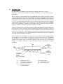
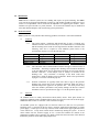
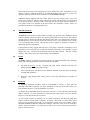
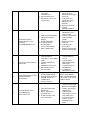
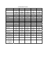
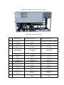
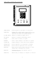
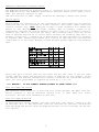
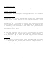
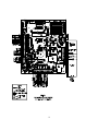
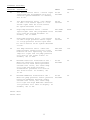
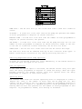
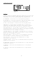
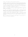
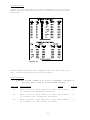
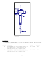
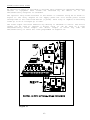
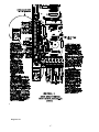
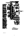
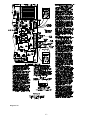
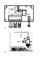
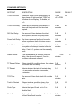
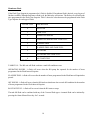
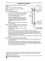
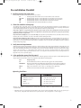
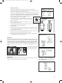
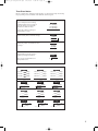
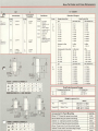
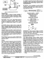
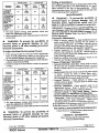
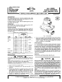
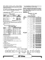
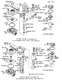
Pressure Fault Switch
On systems where a low feed pressure shut down is required, a feed pressure switch can be
connected to the pressure fault input of P9. If a high pump pressure shut down is required, a high
pressure switch can be connected to this input. If both low feed pressure and high pump pressure
shut down are required, both switches can be connected to this input. Both switches must be either
normally open or normally closed to operate properly.
Pretreat Switch
In systems with pretreatment, a pretreat lockout switch can be connected to the pretreat input of P9.
This switch should operate when the pretreatment device is out of service. NOTE: The output from
the pretreatment device must be a dry contact and must not supply voltage.
Tank Full Switch
In systems with a single tank level switch for controlling the RO pump, the level switch connects to
the tank full high input of P9. If dual level switches are used for controlling the RO pump, the upper
level switch connects to the tank full high input of P9 and the lower level switch connects to the tank
full low input of P9.
I/O Expander Board
If the optional I/O expander board is installed, 2 additional relay outputs and 1 additional switch input
are provided. Refer to figure 4 for the location of terminal strips, jumpers and wiring for this board.
AC power for the relays is connected to the L1 and L2 power terminals of P1. Relay 1 is connected
to this power input and will supply the same voltage. This relay is rated for 120/240VAC at 1HP
maximum. Relay 2 can be selected to supply voltage, 120/240, 5A maximum, or as a dry contact
output. Jumpers J1-J4 are used to select the relay 2 output type. To output voltage, a wire jumper is
installed between J1 and J4 and a second wire jumper is installed between J2 and J3. For a contact
closure output, a single wire jumper is installed between J3 and J4. The 2 relay outputs can be
selected to operate as an auxiliary pump output, a divert output or an alarm output by programming
the Expander Mode Setpoint. Table 2 shows the values used to program the relay outputs.
EXPANDER MODE
RELAY 1
RELAY 2
0
AUXILIARY PUMP
DIVERT
1
AUXILIARY PUMP
ALARM
2
DIVERT
ALARM
TABLE 2
7