1
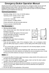
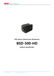
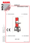
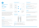
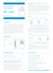
Wireless Passive Infrared Detector
Operation Manual
Wireless passive infrared detector uses advanced digital processing technology with automatic temperature compensation, the battery
voltage insufficient tips and resistance to white light, and other functions. It could send wireless alarm sign to host through detect the
human infrared radiation. It's hard to be effected by environment and low false alarm and safe and reliable and more convenient to
installation and operation and so on.
1. Main features
Using dual infrared sensor and high sensitivity.
SCM intelligent digital processing.
Energy saving design, static current≤50µA.
Anti-electromagnetic interference, low false alarm.
three level sensitivity design.
Automatic temperature compensation.
It can be connected with external DC9-12V power supply. The internal and external power
supply can be switched automatically.
It has battery voltage insufficient hint and low voltage report to host.
Wireless transmitting uses acoustic frequency stabilization, stable and reliable.
2. Technical features
Operating voltage:DC6V(4pcs AAA dry batteries)
external power supply:DC9-12V
Operating current:standly current(battery power)≤50µA standby
current(external powered)≤5mA alarm
current≤25mA
Detection angle: 110°
Detection range: 4-12M(optional) Block
time after power on: 60 seconds Launch
time: 3 seconds
Launch frequency: 315MHz±75KHz
Product dimensions: 105*62*38(without antenna)
Operating temperature: -10℃~+55℃
12m
10m
D
8m
e
t
4m
e
c
t
2m
i
o
n
a
2m
n
g
4m
l
Detection range: 4-12M(optional)
0~15°
e
8m
1
1
10m
0
°
12m
2m
Top view
4m
6m
8m
10m
Side view
Storage temperature: -25℃~+65℃
Products standard:GB16796-2009
3. Product schematic diagram
① PIR: It used to detect the human infrared radiation. Please don' t touch the
④
⑧
surface and keep cleaning. If the surface is dirty, please use cotton ball
①
with 75% alcohol to clean it.
② Power switch: While the power switch push to “on”, the detector begin
⑩
working. While the power switch push to “off”, the detector stop working
and send message to alarm host. The power switch could not effect the
tamper device.
③ Tamper switch: The detector will send alarm message to host while the shell be
opened.
④ Sensitivity select switch: The detector have 3 levels of sensitivity for selecting. “H” is
about 8-12m; “M” is about 6-8m; “L” is about 4-6m. Please choose the sensitivity level
according to the area where you use it. We recommend you to
choose lower level if it can meet your need. Factory default is “H”.
⑤ Mode selection: The detector supply 3 kinds of working modes
1
2
MODE
1
2
MODE
1
2
MODE
Test mode: If the detector is succeed to alarm, it could pause for 10 seconds and prepare
for the next detection. It could be used for walking test while installation and trial, but it could loss lots of power.
Standard mode: It could pause for 10 seconds after a successful alarm and prepare for the next detection.
So we recommend you to choose this mode in our normal situation.
Energy saving mode: It could pause for 240 seconds after a successful alarm and prepare for the next
detection. We recommend you to choose this mode while you use it in crowded places like market and
office and etc.
Notes: Please change the working mode while you tear down the battery and external power input.
⑦
③
②
⑥
⑤
⑨
12m
⑥ Alarm indicate lamp switch: Mini jumper is plugged in “on”, The indicator light shining while launch wireless signal; If mini
jumper is not plugged in, the indicator light is not shining while launch wireless signal.
⑦ Alarm indicate lamp (red): Alarm indicate lamp shining means the detector alarming.
⑧ Low power indicate lamp(green):When the light changes to green, it means the battery of the detector is of low power.
⑨ External DC input: It can input DV9~12V DC voltage( + ). If stop external power supply, it could switch to internal
battery mode to supply power.
⑩ Code bouncing pilotage: Using for transmit. It works with repeater.
4. Installation and operation
4.1 Installation requirements
Please choose the suitable installation position as the infrared detection is more sensitive when body lateral movement relative to
the lens, and poor for vertical motion.
Please pay attention to the angle(around 0~15°) and height(around 2m) of detector, which has great impact on the
protection area.
Detector should be avoid the direct illuminate from the and other emergency light(i.e car headlights),also avoid direct on doors and
windows.
Detector should be avoid installed near any device which emits heat or cold, such as air-conditioners, refrigerators, ovens,
heaters.
The protection area of the detector should be able to look straight ,and no obstacle allowed.
For the detector effect getting worth if the environment temperature close to body, to get the best effect when install in high
temperature, it proposed to be aligned with the lowest temperature in protected areas section
We recommend lower the detection sensitivity when using in the strong interference environment.
The wall for installation should be stable, no shaking. After installation, the detector shouldn't be shaking.
4.2 Connection schematic diagram and installation
The wall for installation should be stable, no shaking. After installation, the detector shouldn't be shaking.
Put into the 4 AAA battery with the director in the battery box, turn power to “ON” and fix the detector at the wall.
MODE
1:Open the cover as follows
1
1
testing
Flat blade screwdriver
2
J5
2:Please choose suitable sensitivity
and working mode according to the
protecting requirement.Please put
batteries into battery box according to
the sign,close the cover and
open the power supply
1
standard
2
2
J5
Power
saving
J5
Top view
J5 factory default standard mode
Sensitivity select switch
H
M
H
M
4- 6 M
L
J3
H
6- 8M
L
M
L
8 - 12M
J3
J3
J3 factory default is “H”
Code bounding piotage:
please modify it under the guide of
professional
Plug-in screwdriver
from here
Adjusting the induction
area right and left.
0~15°
Adjusting the induction
area up and down.
2M
Top view
3: Please press the universal
ball in the universal seat
withuniform strength to
avoiddamaging
4: Please press the universal
ball in the universal seat
withuniform strength to
avoiddamaging
5: Please press the universal
ball in the universal seat
withuniform strength to
avoiddamaging
6: Adjusting the induction area
according to the protecting
requirements.
Side view
7: Finishing installation.
4.3 Simulation demonstration
After the detector powered 60s. The detector will alarm while anyone move 3m(0.75m/s) and the distance between the people and
detector is 8m. The alarm indicator light will shining and start the host alarming. If the demonstration is OK, it means the
installation is success. Otherwise, please check the installation angle and position is right or wrong.
5. Notes
Do not use your hand to touch the surface and keep it clean. Use pily ball stained with 75% alcohol to clean the surface when
dirty.
To make sure of the system work stable, please check and test the detector regularly.
Accident would be reduced by using this product ,but can not be sure no risk at all.For your own safety,please keep vigilant
and safety awareness in daily life in addition to proper use of this product.
We own the right of final explanation of this product