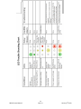
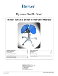
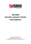
1
N56 W16665 Ridgewood Drive Menomonee Falls, WI 53051 SBS-H2 Hydrogen Gas Detector Kit For battery charging rooms and other areas where hydrogen gas may be present INSTALLATION, OPERATING & MAINTENANCE INSTRUCTIONS Protects Life, Property, and Profits Compliant with NFPA 70E ® and IEEE recommendations Hydrogen sensor is UL Class 1 Division 2 1-800-554-2243 www.sbsbattery.com ■ [email protected] SBS-H2 Users Manual 1 Rev 1.4 January 6th 2013 Table of Contents: Description Overview Benefits How It Works Specifications Sensor Mounting Location Installation Operation Electrical Testing Calibration LED Trouble Shooting Chart Page 3 3 3 4 4 5 6 10 10 10 11 Section 1.0 2.0 3.0 4.0 5.0 6.0 7.0 8.0 9.0 10.0 11.0 Part Numbers & Options: Part No. SBS-H2 H2-JB H2-SENSOR H2-100FT-CABLE H2-CALKIT E190399 Description Hydrogen Gas Detector (Includes: Main Unit, (1) sensor & (1) 25ft cable) Junction Box, 4 11/16” X 4 11/16” Metal, with Knockouts Additional/Replacement Hydrogen Gas Sensor with 25ft Cable Custom 100 Ft Cable and mA Converter (no sensor) Field Calibration Kit for SBS-H2 110vac 3 Prong AC Cord, 10 Ft, 18AWG Warnings: This detector is added protection, not a substitute, for prudent safety measures where hydrogen gas is present. For large or highly sensitive areas, you may have to use two or more detectors with 1 or 2 sensors each for increased detection. The hydrogen sensor does not provide protection from fires or hydrogen explosions. The relay contacts are intended to be connected to a safety system, enabling audible alarms, system shutdown, ventilation, or other measures to ensure safe handling and use of hydrogen gas. Ensure that your installation complies completely with all relevant local, State, Federal, and OSHA safety and health regulations If sensor responds, there is a risk of combustion or explosion. To avoid injury leave area immediately. The hydrogen sensor is calibrated for operation in air. Tampering with the sensor or operation in other gas environments can lead to inaccurate readings and possible permanent damage if operating in a reducing atmosphere or 100% hydrogen. The hydrogen sensor is silicone resistant but uncured silicone compounds or extended exposure to silicone off gassing, or high concentrations of refrigerant gasses related to a leak, can give inaccurate readings in the sensor. SBS-H2 Users Manual 2 Rev 1.4 January 6th 2013 1.0 Overview Hydrogen gas detectors act as monitors that provide alarms as well as control functions such as controlling exhaust fans, remote alarm and signaling, building management interfacing and more for the protection of your facility. Batteries on charge emit hydrogen gas after reaching 80% of the recharge point. Examples of typical hydrogen emissions per lead-acid battery are: Battery Size 12 Volt / 500 Amp-Hour 24 Volt / 720 Amp-Hour 36 Volt / 935 Amp-Hour 48 Volt / 850 Amp-Hour Hydrogen Gas 3.5 Cubic Feet/hr. 10.1 Cubic Feet/hr. 19.8 Cubic Feet/hr. 23.9 Cubic Feet/hr. Concentrations of 4.1% to 75% H2 mixed with air can be explosive. Sparks or hot surfaces can ignite them. A hydrogen gas detector in your battery room will provide a warning and facilitate dissipation of hydrogen concentrations before they reach the lower explosive limit (LEL) of 4.1%. 2.0 Benefits In addition to protecting your employees and your property, the detector may also reduce the following costs: Electricity - Heating - Air Conditioning Instead of continuously running an exhaust fan to prevent hydrogen gas accumulation, use the detector to activate the fan only if the concentration reaches 1%. Insurance Installation of a detector in areas where batteries are charged may result in a premium reduction. 3.0 How it Works Should the concentration of hydrogen gas in the air surrounding the sensor reach 1% by volume, the "1% Warning" yellow LED will light and the 1% internal relay will energize. Should the hydrogen gas concentration reach 2% by volume, the "2% Alarm" red LED will flash and an alarm will sound. Either relay can be used to activate a remote exhaust fan and/or alarm. Automatic operation, continuous monitoring, high sensitivity & stability,and solid state reliability. The unit is also intrinsically safe using 120/240 VAC 50/60 Hz or 12-48 VDC operating voltages, low in cost and easy and versatile to install. SBS-H2 Users Manual 3 Rev 1.4 January 6th 2013 4.0 Specifications Dimensions: 4.75"L x 5.25"W x 1.4"D (display only) Wall Mounting: Two 3/16" screws Junction Box Mounting: Requires 4 11/16” x 4 11/16” 2-gang junction box (SBS Part# H2-JB) Power Requirements: 120/220 VAC, 50 / 60 Hz or 12VDC Isolated or 14 to 48 VDC *** An earth ground must be supplied to the GND terminal when using the 12VDC and Isolated (Gnd) inputs for 12 Volt supply to the unit. Relays: 1% Warning Relay, 1 Normally Open & 1 Normally Closed contact 2% Alarm Relay, 1 Normally Open and 1 Normally Closed contact 5.0 Sensor The sensor consists of a ceramic sensing element whose electrical conductivity increases when hydrogen is adsorbed on its surface. Conductivity of the sensor is proportional to the gas concentration which is continuously monitored by an electronic circuit. The sensor only monitors pure hydrogen gas (H2) and will not alarm due to Hydrogen Sulfide (H2S) – which has an odor at very low concentrations. Hydrogen Sensor SBS-H2 Users Manual 25 Ft Cable extension 4 Rev 1.4 January 6th 2013 6.0 Mounting Location Hydrogen is colorless and odorless; the lightest of all gases and thus rises. The hydrogen sensor, therefore, should be installed at the highest, draft-free location in the battery compartment, cabinet, or room where hydrogen gas would accumulate. The Alarm Box can be mounted at eye level or wherever is convenient for the user. The size of the area one sensor will protect depends upon the battery compartment or room. The detector measures hydrogen gas concentration in the air immediately surrounding the sensor. Hydrogen gas may accumulate in several areas of the battery compartment or room therefore; individual detectors should be installed in each of these areas. Mounting and Power Options: Wall Mountable Integrated back mounting plate allows user to easily mount directly to any wall using qty.2 3/16” screws (not included). Wiring Power and Alarm Wires can be ran through the sides of the unit Alarm Wiring Input Power Junction Box Mountable Mounts to a standard, 4 11/16“ x 4 11/16“ 2-gang junction box (SBS Part# H2-JB). Hardwire Run AC or DC power and alarm wires through back of the unit, into the gang box and out through conduit. SBS-H2 Users Manual 5 Rev 1.4 January 6th 2013 AC Cord -not included (SBS Part# E190399) Unit shown with 3-prong grounded AC Cord (18+ AWG) 7.0 Installation Hydrogen gas has only 7% of the density of air, and thus rises. Your hydrogen gas detector should be installed at the highest, draft-free location in the battery room, cabinet, or compartment where hydrogen gas would accumulate. Carefully remove the cover by pulling it off the detector. Attach the detector to the wall, ceiling, or optional junction box using the mounting holes at the top and bottom of the detector mounting plate. For hard wiring using conduit, the detector box will fit onto the optional junction box. The detector has terminal blocks for connection to a single-phase 120 VAC 50/60 Hz power source, OR a +12 VDC Regulated Power Source or a +14-48 VDC power source. It also has two internal alarm relays. A 1% warning relay that is activated at 1% concentration of hydrogen gas and a 2% alarm relay that is energized at 2% concentration of hydrogen gas. The relays can be used to switch on a remote exhaust fan and/or to turn on an alarm. For 120 VAC power, use 18 gage stranded wire minimum (Belden 19348, equivalent or better). For relay wires, use stranded wire (Belden 8473, equivalent or better). Maximum wire size for connector terminations is 14 AWG stranded copper wire. Power Requirements: Voltage VDC 12 VDC 24 VDC 48 VAC 120 Current (A) 1 Sensor 2 Sensors 0.154 0.302 0.090 0.167 0.052 0.090 0.035 0.062 Power (W) 1 Sensor 2 Sensors 1.848 3.624 2.160 4.008 2.496 4.320 4.200 7.440 The detector's relay dry contacts are rated at 10A/250VAC, sufficient for most 1/3 HP exhaust fans. For higher current requirements, add an external relay. Locate the Sensor installation point within 25 feet of the detector and mount the sensor. Run the supplied cable from the sensor to the detector and connect to the Sensor 1 input labeled on the cover. SBS-H2 Users Manual 6 Rev 1.4 January 6th 2013 For installation of a second sensor One additional sensor may be added to each detector. Multiple detectors can be installed to meet the space coverage requirements of your particular installation. Locate the 2nd sensor installation point within 25 feet of the detector and mount the sensor. Connect the cable from the second sensor to the Sensor 2 input labeled on the cover. On the detector printed circuit board, remove the jumper on P9 to enable the second sensor input. Either sensor is capable of triggering a warning or alarm condition. Switching from Voltage to Current Output- Required when using cable longer than 100 ft. When using cable exceeding the 100FT sensor cable (SBS Part# H2-100FT-CABLE), the Sensor jumper must be moved on the sensor input from the off condition to the on condition, so it covers both pins. 1. Removing the front snap on cover will reveal the inner electronics of the alarm box. 2. Locate the signal output select jumper(s) (P5 for Sensor 1 and P6 for Sensor 2). 3. Install the jumper across the two pins to enable the current output mode (see photos) Note: (Alarm will emit a “chirp” noise if sensors are not connected) Sensor Disabled (40mA Signal Output) Sensor Enabled (Voltage Signal Output) Wiring Diagram: 1. The detector has 2 internal relays. One relay energizes when the sensor detects a 1% concentration of hydrogen gas in the air surrounding it. The second relay contact energizes at a 2% concentration. The detector's internal relays are rated: 10 amps at 250 volts ac; 10 amps at 30 volts dc; 1/3 horsepower at 125 volts ac; 1/2 horsepower at 250 volts ac. SBS-H2 Users Manual 7 Rev 1.4 January 6th 2013 If the load you have is higher than these relay ratings, add an external relay (shaded item in the sketch above). Alarm System Electronics: Please refer to the photos below showing proper power and relay connection points in the detector. It is advisable to use a twisted pair of 14 gage wires for the relay contacts to help reduce any interference within the battery room that may cause false alarms. A. Multiple Sensor Jumper - Select between single or multiple sensor set-up. default jumper settings: single sensor (Jumper on P9 Only) Place a jumper on P8 to disable SENSOR 1 Place a jumper on P9 to disable SENSOR 2 B. Signal Output Select Jumper (Volts/Amps) (P5 for Sensor #1) (P6 for Sensor #2) Select between voltage or milliamp output. default setting: voltage output Enabled amp output by installing the jumper on these pins (lift jumper and slide over to short pins) C. Normally Open (NO) Relay for Warning Condition (1% H2) D. Normally Open (NO) Relay for Alarm Condition (2% H2) E. Test System Push Button F. Calibration Potentiometers (DO NOT ADJUST – WILL VOID CALIBRATION) F B B C A D E SBS-H2 Users Manual 8 Rev 1.4 January 6th 2013 Terminal Connection Diagram: 1% Warning Contacts COM N/O N/C AC Power Supply Terminals 120VAC LINE EARTH (GND) NEUTRAL DC Power Supply Terminals +14-48VDC +12 VDC + 12 VDC Negative GND (ISO) Earth GND EARTH(GND) COM N/O N/C 2% Alarm Contacts OR +14-48 VDC Using the Mechanical Relays: 1. Remove the front cover of the detector by pulling straight off the body. This will reveal the inner electronics of the alarm box. 2. Locate items C and D, and determine which condition you would like to use the relay to be related to. Use Relay C for the warning condition (1% H2) and relay D for the alarm condition (2% H2). 3. Restore the front covering of the alarm box and re-secure the two removed screws. 8.0 Operation Keep the detector on at all times. A Green LED indicates that the detector is powered on. SBS-H2 Users Manual 9 Rev 1.4 January 6th 2013 When power is first turned on, a warm up period of 4 hours will elapse before the detector will start to function. This delay is to prevent false activation of the internal relays and alarm. The GREEN LED will flash during the warm up period and then turn solid green once the warm up is complete. If the concentration of hydrogen gas in the air surrounding the sensor reaches 1% by volume, the yellow LED will light and the 1% internal relay will initiate(which can be used to activate a remote fan and/or alarm). Should the concentration reach 2%, the red LED will flash, the internal warning alarm will sound, and the 2% internal relay will energize. The 1% relay will remain energized & the yellow LED will remain on. When the concentration decreases below 2%, the red LED will turn off, the internal alarm will stop, and the 2% relay will de-energize. When the concentration falls below 1%, the 1% relay will de-energize and the Yellow LED will turn off. 9.0 Electrical Testing (after the input power is on for 4 hours) A "push-to-test" button is located on the front of the unit. Push and hold this button for approximately 10 seconds to test the unit's electronic circuitry. The caution and warning LEDs will light in sequence; the relays will activate whatever is connected to them and the internal warning alarm will sound. Note: The "push-to-test" button does NOT test the sensor itself. 10.0 Calibration The Sensor and display have been calibrated at the factory for hydrogen gas and should not need adjustment at the time of installation. The SBS-H2 Display can be *calibrated in the field using a calibration kit (SBS Part# H2CALKIT) or the sensor and display can be sent to SBS for calibration. SBS Part# H2-CALKIT calibration kit** shown above *Sensor can accept up to 3 calibrations SBS-H2 Users Manual / 10 Rev 1.4 **Sensor not included with calibration kit January 6th 2013 SBS-H2 Users Manual 11 Rev 1.4 January 6th 2013 The information in this sheet has been carefully reviewed and is believed to be accurate; however, no responsibility is assumed for inaccuracies. Storage Battery Systems, LLC. Reserves the right to make changes without further notice to any product, datasheet, technical data bulletin, or website. Storage Battery Systems, LLC. makes no warranty, representation of guarantee regarding the suitability of its product for any particular purpose, nor does Storage Battery Systems, LLC. assume any liability arising out of the application or use of any product and specifically disclaims any and all liability, including without limitation consequential or incidental damages. “Typical” parameters can and do vary in different applications. All operating parameters, including “Typical” must be validated for each customer application by customer’s technical experts. Storage Battery Systems, LLC. products are not designed, intended, or authorized for use as components in systems intended for surgical implant into the body, or other application intended to support or sustain life, or for any application in which the failure of the SBS product could create a situation where personal injury or death may occur. Should buyer purchase or use SBS products for any such unintended or unauthorized application, Buyer shall indemnify and hold Storage Battery Systems, LLC. and its officers, employees, subsidiaries, affiliates, and distributors harmless against all claims, costs, damages, and expenses, and reasonable attorney fees arising out of, directly or indirectly, any claim of personal injury or death associated with such unintended or unauthorized use, even if claim alleges that Storage Battery Systems, LLC. was negligent regarding the design or manufacture of the part. In the case of a defect in the sensor, Storage Battery Systems, LLC. shall not be liable for any damages which may result, including, but not limited to, loss of revenue, property, or life. In any event, Storage Battery Systems, LLC. shall limit liability to replacement of the defective unit. Storage Battery Systems, LLC. does not convey any license under its patent rights nor the rights of others. N56 W16665 Ridgewood Drive Menomonee Falls, WI 53051 1-800-554-2243 SBS-H2 Users Manual www.sbsbattery.com 12 Rev 1.4 [email protected] January 6th 2013