1
SBS-8400
BATTERY CAPACITY TESTER
USER MANUAL
Rev. 2.1 12-14
STORAGE BATTERY SYSTEMS, LLC
N56W16665 Ridgewood Dr., Menomonee Falls WI 53051
Phone: (800) 554-2243
Fax: (262) 703-3073
Website: www.sbsbattery.com
SBS-8400 USER MANUAL
Contents
1. Introduction
1.1
Features
1.2
System Components
2. Main Technical Parameter
2.1
Environment & Conditions for Use
2.2
Structure & Weight
2.3
Working Power Supply
2.4
Input Voltage from Battery strings
2.5
Discharge Current Range
2.6
Parameter Display & Measure Accuracy
2.7
Protection & Warning
2.8
Data Management & Communication
3. Basic Operational Principle
3.1
Battery Testing Principle
3.2
Constant Current Principle
4. Operating Instructions
4.1
Environments Requirement
4.2
Panel Description
4.3
Main Machine Connection
4.4
Wireless Modules Connection
4.5
Starting Up and Input Operation
4.6
Check the Connection of the Wireless Modules
4.7
The Preset Function
4.8
Discharge
4.9
Download the Data to PC
4.10
System Setup
4.10.7 Calibration
4.11
Charge Monitoring Function
4.12
Multiple units in parallel
5. PC Software Instruction
5.1
Main Functions
5.2
Install Analysis Software to PC
5.3
Real Time Recording During the Testing
5.4
Download Data File from USB Disk
5.5
Generate Excel Test Report
6. Precautions
7. After-Sale Service
SBS-8400 USER MANUAL
1. Introduction
Battery-based backup systems have become an ever-increasing source of providing
emergency power to critical systems and components. Maintaining these systems
and knowing that they will be able to perform when called upon in an emergency
has led to an increasing demand for testing methods to guarantee reliable operation.
In addition, new requirements and recommendations (FERC, NERC, IEEE, etc...) are
requiring more stringent attention to the reliability and performance of batteries
used in these critical applications.
As we know, there are many factors which determine the actual service life that a
battery string will reliably perform before failures or reduction in capacity requires
replacement. While period maintenance and routine monitoring of measurements
gives you some idea of a battery’s condition, it is only by actually testing the capacity
of the battery string that you know what its capabilities are and how close it is to its
end of useful service life.
With these ideas in mind, SBS has developed the SBS-8400 as an advanced, highly
accurate and intellectual testing system for conducting load testing of battery strings.
With innovative features, such as wireless data collection, real time monitoring, and
integrated software, the SBS-8400 is the tool of choice for consistent, reliable and
affordable battery capacity testing.
Advantages of the SBS-8400:
a) Wireless battery monitoring technology - Available for 1.2V/2V/6V/12V cells
voltage monitoring.
b) Each wireless module can monitor 4 cells simultaneously - Compared with
traditional methods where each module can only monitor 1 cell, the new
module design requires only a quarter of the number of old-fashioned modules.
(Only 6 wireless modules for 48V battery strings.)
c) Parallel monitoring of multiple battery strings - The SBS-8400 can
simultaneously record the actual discharge currents and voltages of each battery
strings under test. (Accessories, extra current clamps are needed for multi-string
testing.)
d) Automated constant current control during on-line tests - During the discharge,
the current displayed in the LCD = the discharge current of battery string. The
SBS-8400 is capable of monitoring the current created by the main machine +
the current of the actual load. This allows for testing the battery system and
automatic adjustment based on the system real and artificial load.
e) Selectable number of low voltage limits - This feature allows the test to
continue instead of stopping as soon as the first cell reaches the low cell voltage
setting and allows for testing to continue after a weak / bad cell is jumped out of
the string.
Page 3 / 30
SBS-8400 USER MANUAL
f)
g)
h)
i)
j)
k)
l)
m)
Simplified menu design - The simplified menu allows for easy test set up and
operation.
Light weight alloy heat sink elements - New generation materials increase safety
and thermal transfer of heat to air.
Auto scan and display of the voltage data for each battery during the discharge
Graphical histograms display the status of each cell throughout the discharge,
and the use of different colors to highlight the lowest and the highest voltage
can simplify the identification of possible problems.
5.7 inch colorful touching LCD screen - The large touchscreen allows menu
selection and programming, and shows all parameters and the voltage histogram
during the discharging process.
Intelligent judgment program - SBS-8400 continuously monitors voltages and
regulates test progress to shutdown parameters. Automatic adjustment of
discharge current level allows this revolutionary program to keep the test stable
and smooth.
Presetting function for discharge parameters - SBS-8400 provides 30 presets for
setting up discharge parameters in advance; this design can simplify the
programming operation and speed up testing.
Real Time PC Logging- Powerful software for downloading real time data, or use
the USB port to download the data after the discharging process. PC analysis
software assists users in analysis of the data and creation of test reports.
8M internal memory - SBS-8400’s internal memory can record several sets of
test result data independently and the menu interface provides basic
management operations like reviewing, analyzing or deleting test results.
The Advantages / Features of SBS-8400 Analysis Software:
a) Allows data downloading and analysis through real time communications or USB
memory device downloads.
b) The software interface includes: battery/cell voltages curves and bar charts,
group voltage curve, current curve, capacities histogram and a raw data matrix.
c) Powerful capacity calculating function - the software calculates the capacity of
each battery in the tested group.
d) The software shows the data in various forms such as bar charts, curves, and
table formats. Users can magnify or minimize any windows to view more details.
e) Automatically creates EXCEL data reports; convenient to send or download the
data.
SBS-8400 has multiple protective functions, which include the audible alarms,
warning lights and clear interface prompts.
SBS-8400 is a compact, lightweight, simple to operate and highly accurate testing
platform. SBS-8400 is versatile in its ability to discharge test 12V, 24V, 48V, 72V, 96V,
110V, 120V, 220V, 240V battery strings etc., across many applications.
Page 4 / 30
SBS-8400 USER MANUAL
1.2 System Components
The SBS-8400 battery capacity tester includes the main machine, wireless modules
for cells monitoring (optional), wireless signal receiver and PC analysis software.
The main unit consists of a color LCD screen, data processing unit, data monitoring
unit, auxiliary power unit, power consumption unit and panel operation unit.
color LCD screen
SBS-8400 Battery
discharge &
capacity tester
main machine
data processing unit
wireless modules for
cells monitoring
data monitoring unit
PC analysis software
wireless signal
receiver
auxiliary power unit
power consumption
unit
panel operation unit
2. Technical Parameters
2.1
2.1.1
2.1.2
2.1.3
2.1.4
Environment & Conditions for Use
Operating temperature:
20°F ~ 122°F (-5℃ ~ +50℃), full power, forced air cooling
Storage temperature:
-40°F ~ 150°F (-40℃ ~ +70℃)
Relative humidity:
≤90% 105°F±5°F (40℃±2℃)
Altitude limit:
0~2000m,
20°F ~ 122°F
(-5℃~+50℃), full power
2000m~4000m, 20°F ~ 90°F (-5℃~+30℃), full power;
90°F ~ 122°F (30℃~+50℃), 80% of ratings.
2.2 Structure & Weight
Dimensions: (length*width*height):
SBS-8400:
26.4” x 9.05” x 14.6” (670mm x 230mm x 370mm)
Page 5 / 30
SBS-8400 USER MANUAL
Weight:
SBS-8400:
52.9 lbs. (24 kg) {main tester only}
2.3 Working Power Supply
SBS-8400:
AC 120V single phase 45Hz~65Hz (220VAC optional)
2.4 Input Voltage from Battery String
SBS-8400:
10 ~ 300V
2.5 Discharge Current Range
Voltage range
Current range
10-15V
0-60 A
15V-60V
0-120 A
86-150V
0-120 A
190-280V
0-60 A
2.6 Display & Measurement Accuracy
LCD Display: 5.7 inch LCD color touch screen
Displayed discharge current: resolution 0.1A
accuracy≤±0.5%
Displayed battery strings voltage: resolution 0.1V
accuracy≤±0.5%
Displayed cells voltage: 1.2V/2V/6V cells resolution 0.001V
accuracy≤±0.05%
12V cells resolution 0.01V
accuracy≤±0.05%
2.7 Protection & Warning
Protection features of the SBS-8400:
2.7.1 DC input overvoltage, polarity reversal at battery connection, DC over current
during discharge, and system over temperature.
2.7.2 Warning light and audible alert will activate, and the LCD screen will show
message / prompt.
2.8 Data Management & Communication
2.8.1 Discharge data management
a) Data sampling is saved continuously and automatically, so test records are not
lost even due to a loss of power.
b) Allows for manual review of data.
c) Allows for reading & downloading data via the communication port.
d) Displays the remaining capacity of the internal memory.
e) Smart delete selection: delete all or delete the selected record from memory.
Page 6 / 30
SBS-8400 USER MANUAL
2.8.2 Preset Test Parameters
The “Preset” interface allows the user to program and store in the internal memory
of the SBS-8400 up to 30 test preset parameters for quick selection and setup.
2.8.3 Communication
a) Internal wireless signal receiver allows the SBS-8400 main unit to record the cell
monitoring & sampling data.
b) Via the RS232 port in SBS-8400 main unit, a PC can be connected to display real
time discharge data.
c) Via the USB port in SBS-8400 main unit, test result data can be transferred to a
PC by a USB-disk.
d) Via the Parallel control port, SBS-8400 main unit can control a SBS-S series DC
load bank.
3. Basic Operational Principles
3.1 Battery Testing Principle
Because of the differences in materials, construction, craftsmanship, installation
environments, and maintenance practices, battery strings from different
manufacturers have many unique characteristics. Even the same types of batteries
from the same manufacturers will see variances in performance and capacity from
one string to another. There are many ways to predict the condition of a battery
systems performance and remaining life expectancy, however, the IEEE capacity
testing procedures are the only definitive proof of a battery systems ability to
perform as specified by the battery manufacturer.
Nowadays, with the popularity of VRLA batteries, fewer indications are available to
determine the condition of a battery.
We believe:
a) The battery voltage in float charge operation and the batteries true capacity
have no direct correlation.
As we know, batteries which have a low capacity can still display a normal voltage in
float mode. Simple interpretation of available data is not accurate in determining if a
battery will perform as required when called upon.
b) Full rated capacity discharging is still the most accurate method to test the
performance of batteries.
For systems which are created by a number of cells connected in series, the actual
capacity of battery string relies on the ability of the worst cell to perform to capacity.
The principle goal of capacity testing is to find these poorly-performing cells and
replace them to increase the service life and reliability of the whole battery system.
Applying a constant current as specified by the manufacturer for a specific period of
time allows for monitoring the batteries’ voltage to ensure the cell remains above
Page 7 / 30
SBS-8400 USER MANUAL
the specified cut off voltage and allows us to determine the battery and systems
actual performance capacity as a way of ensuring the systems’ performance.
Examining a voltage drop curve for the discharge rates:
From the curves, we know what the performance is supposed to be at a given rate of
discharge and this is the most uniform and accurate method for estimating the
capacity of a battery.
3.2 Constant Current Principle
The internal circuitry of the SBS-8400 uses a PWM (pulse width modulation) control
technique. Controlled by the CPU and sensing circuits, the power circuit can
discharge the battery string with very accurate, automatically corrected control.
Data collection and interpretation by the software is automatic and accurate.
Page 8 / 30
SBS-8400 USER MANUAL
4. Operating Instructions
4.1 Environment Requirement
The unit should only be used in environments that are free from dust and flammable
or explosive gases. It should be properly ventilated to dissipate heat produced.
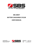
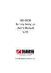
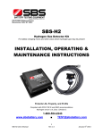
4.2 Panel Description
Air cooling fans
Antenna
External
current
measurement
LCD screen
Wired modules
input
RS232 port
Parallel input
USB port
AC input socket
DC breaker
Power switch
Cable socket
Main machine
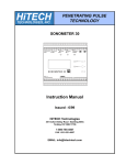
Power light (green)
Communication light
(red)
Alligator clip
(4 yellow, 1 red, 1 black)
Wireless module for 2V/6V/12V—SBS-2612
Page 9 / 30
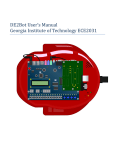
SBS-8400 USER MANUAL
Power light (green)
Communication light
(red)
Alligator clip
(4 red, 1 black)
Wireless module for 1.2V/2V-SBS-12612
4.3 Main Machine Connections
120V AC 60Hz
Power Source
220V AC 50Hz
Power Source
(Optional)
Power supply cord
DC Breaker
Power Cable (black)
Power Cable (red)
Battery String
4.3.1 Use the power cables (1 red, 1 black) to connect the SBS-8400 to the battery
string to be tested.
4.3.2 Use the power supply cord to provide the SBS-8400 with an AC power source.
a) The SBS-8400 supports 120V AC 50Hz/60Hz external AC input power.
b) If your power source is 220V AC 50Hz/60Hz, please use the optional 220V AC to
110V AC transformer to power the unit, or inform us when you plan to order a
SBS-8400 and unit will be shipped to support 220V AC.
Page 10 / 30
SBS-8400 USER MANUAL
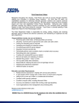
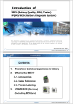
4.4 Wireless Modules Connections
Before connecting the wireless modules, please install the antenna.
Wiring Diagram
4.4.1 SBS-2612 wireless modules (for 2V) connections
SBS-2/6/12 Wireless Module
Yellow 4
Yellow 3
Yellow 2
Yellow 1
Red
Black
Wireless module number and the battery to connect
For example: NO.1 module -- Connect to cells NO.1-NO.4 (from positive)
NO.2 module -- Connect to cells NO.5-NO.8 (from positive)
NO.3 module -- Connect to cells NO.9-NO.12 (from positive )
………..
Cell
Cell
Cell
Cell
NO.1
NO.2
NO.3
NO.4
Cell
Cell
Cell
Cell
NO.5
NO.6
NO.7
NO.8
Cell
Cell
Cell
Cell
NO.4K+1
NO.4K+2
NO.4K+3
NO.4K+4
NO. 1 Wireless module
NO. 2 Wireless module
NO. K Wireless module
4.4.1.1 Reading the module number from the modules’ labels, find the correct cells
to connect the module to. Do not connect the modules to 4 batteries which are not
in series like No. 1, 5, 8, 9 - misconnection will likely damage the module
immediately!
4.4.1.2 Use the alligator clips (1 red, 1 black, 4 yellow) to connect modules to the
batteries. Please follow the correct wiring rule “Yellow 1 to Yellow 4, from long to
short. A wiring diagram is printed on the label of the modules for your reference.
Page 11 / 30
SBS-8400 USER MANUAL
4.4.2 SBS-2612 wireless modules (for 12V, 6V) connection
Wiring Diagram
SBS-2/6/12 Wireless Module
Yellow 4
Red
Yellow 3
Yellow 2
Yellow 1
Black
Wireless module number and the battery to connect
For example: NO.1 module -- Connect to batteries NO.1-NO.4 (from positive)
NO.2 module -- Connect to batteries NO.5-NO.8 (from positive)
NO.3 module -- Connect to batteries NO.9-NO.12 (from positive)
………..
Cell
Cell
Cell
Cell
NO.1
NO.2
NO.3
NO.4
Cell
Cell
Cell
Cell
NO.5
NO.6
NO.7
NO.8
Cell
Cell
Cell
Cell
NO.4K+1
NO.4K+2
NO.4K+3
NO.4K+4
NO. 1 Wireless module
NO. 2 Wireless module
NO. K Wireless module
4.4.2. Read the module number from the label the modules, find the correct cells to
connect the module to. Do not connect the modules to 4 batteries which are not in
series like NO.1,5,8,9, misconnection will likely damage the module immediately!
4.4.2.1 Use the alligator clips (1 red, 1 black, 4 yellow) to connect modules to the
batteries, please follow the correct wiring rule “Yellow 1 to Yellow 4, from long to
short”, and the wiring diagram also print on the label of the modules.
Page 12 / 30
SBS-8400 USER MANUAL
4.4.3 SBS-1.2/2 wireless modules (for 1.2V, 2V) connection
Wiring Diagram
SBS-1.2/2 Wireless module
Black
Red 3
Red 2
Red 1
Wireless module number and the battery to connect
For example: NO.1 module -- Connect to cells NO.1-NO.4 (from positive)
NO.2 module -- Connect to cells NO.5-NO.8 (from positive)
Red 4
NO.3 module -- Connect to cells NO.9-NO.12 (from positive)
………..
Cell
Cell
Cell
Cell
NO.1
NO.2
NO.3
NO.4
Cell
Cell
Cell
Cell
NO.5
NO.6
NO.7
NO.8
Cell
Cell
Cell
Cell
NO.4K+1
NO.4K+2
NO.4K+3
NO.4K+4
NO. 1 Wireless module
NO. 2 Wireless module
NO. K Wireless module
4.4.3.1 Read the module number from the label the modules, find the correct cells to
connect the module to. Do not connect the modules to 4 batteries which are not in
series like NO. 1, 5, 8, 9 – the misconnection will likely damage the module
immediately!
4.4.3.2 Use the alligator clips (4 red, 1 black) to connect modules to the batteries,
please follow the correct wiring rule “Red 1 to Red 4, from long to short”, and the
wiring diagram printed on the label of the modules.
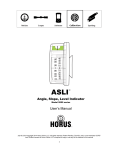
4.4.4 Connection guide when cell quantity is not a multiple of 4
4.4.4.1 SBS-2/6/12 wiring for last 4 to 1 cells
Page 13 / 30
SBS-8400 USER MANUAL
4 yellow wires, from left to right = from long to short
means this wire is not connected
|
separates the groups of cells
Last four 2V cell
Module
Last four 6V/12V cell
Module
Module
Last three 2V cell
Module
Last three 6V/12V cell
Module
Module
Last two 2V cell
Module
Module
Last two 6V/12V cell
Module
Module
Last one 2V cell
Module
Module
Module
Last one 6V/12V cell
Module
Module
Page 14 / 30
Module
SBS-8400 USER MANUAL
4.4.4.2 SBS-1.2/2 wiring for last 4 to 1 cells
4 red wires, from left to right = from long to short
means this wire no need to connect
separate the last cells with other cells
Last four 1.2V/2V cell
Module
Last three 1.2V/2V cell
Module
Module
Last two 1.2V/2V cell
Module
Module
Last one 1.2V/2V cell
Module
Module
4.4.5 Spare modules and reassigning module numbers
4.4.5.1 No. 0 spare modules
With each module set you will find No. 0 spare modules. They
have the following label: No number assigned. They can be
addressed to any module No., and allow testing to continue if
any assigned module should fail.
No. 0 Spare module label
4.4.5.2 To Activate a No. 0 spare module:
When any assigned module fails (for example, No.
3 module), you can connect one of the spare
Page 15 / 30
Module
SBS-8400 USER MANUAL
modules to 4 cells, just like a normal module. Disconnect all other modules.
Re-address the spare module to No. 3 to replace the failed one by entering the
‘Config Module Addr:’ of the 'Setup' menu. Set '003#' and press 'config'. The spare
module will become the new No. 3 module.
4.4.5.3 How to Erase and Reassign the Assigned Modules (Numbered)
If you run out of spare modules, and one of the assigned modules fails (for example,
No. 3 module fails) you can erase No.15 and reassign to No. 3 for this urgent
requirement.
a) Open the No. 15 module box; you will see a
small button on the PCB. (Yellow frame in the
picture.)
b) While holding this button down continuously,
connect it with 4 cells, just like you would a
normal module. It will power on, and then wait
10 seconds. Release the button.
c) Check 'BatteryView' in LCD, if Cells 57- 60
(normally on No. 15 module) have no data, it
means No. 15 module has been reset to a No.
0 spare one.
d) Follow the procedure in '4.4.5.2 To Activate a No. 0 spare module', to edit it to
No. 3.
4.5 Starting Up and Input Operation
4.5.1 After the SBS-8400 has been connected to the battery
system, turn on the “AC” power switch.
Power switch
4.5.2 A welcome interface will appear where you can see the unit
identification. Press anywhere on the screen to go to the main menu. If 10
seconds elapse, the system will jump to the main menu automatically.
Page 16 / 30
SBS-8400 USER MANUAL
4.5.3 SBS-8400 input method: touchpad directly on LCD screen.
The Welcome Screen
The Main Menu
4.6 Check the Connection of the Wireless Modules
4.6.1 Press “BatteryView” on the main menu to enter the table interface, if all
wireless modules are connected correctly, you will see the voltage of each cell. If the
voltages of some cells are not showing, please re-check the wireless module
connections.
The highest & lowest voltage
cell in battery string
Table
Each screen can show 24 cells.
For more than 24 cells, press “Next”
Chart
Back to the main menu
“Prev” to see the other pages.
4.6.2 Press “Chart” to see the histogram for each cell in the string.
Page 17 / 30
SBS-8400 USER MANUAL
4.6.3 Both the table and chart interfaces show 24 cells at a time. If the tested battery
string has more than 24 cells, press the “Next” & “Prev” to see the other cells.
4.6.4 Press “Exit” to go back to the main menu
4.7 The Preset Function
4.7.1 The preset function allows 30 programmable locations to save discharge test
setups. You can select any of the preset tests and press “Apply” to use those
discharge parameters. The SBS-8400 supports manual setting in the discharge
interface without using the preset features.
Press “Preset” on the main menu to enter the preset interface
Preset parameter number
Preset
TestTime: the discharge time
AhRate: The rated capacity of
TestCurr: discharge current (if
the tested battery string
choose CCurrent Mode)
TestCapa: the capacity need
HourRate: The hour rate of
to be discharged
discharge
BattSum: cell qty in battery
SaveTime: the time interval
string
of the data recording
GrpLowV: the lower limit
TestMode:
voltage of battery string
CCurrent (constant current)
BattLowV: the lower limit
CKW (constant power)
voltage of cells
PowerSet: discharge power (if
Recover all parameters
using CKW mode)
to default values
ACError: the reaction for AC
To change Parameter number
power losing, for SBS-8400,
Param 1, Param 2, Param 3…..
This item will lock at ‘Stop’
#BattLow: qty of cells which
voltages below “BattLowV”
Press “Modify” to locate the preset parameters
need to be changed, “+”, “-” to change value,
#Strings: number of strings in
“Cancel” to quit. After all setting, press “Apply”
parallel being tested at once
to save
4.7.2 “TestCapa”, “TestTime”, “BattLowV”, “GrpLowV” are the test stop conditions, if
any of these set-points is reached, the discharge will stop automatically.
4.7.3 For 1 battery string discharge, please keep “#Strings” at “001G”; if parallel
discharging 2-4 strings is needed, 2-4 times the wireless modules will be needed. The
discharge current will be ½ - ¼ for each string being tested.
4.7.4 If you want the discharge to stop when one bad cell reaches the “BattLowV”,
please keep “#Battlow” in “001#”. If you want the discharging to stop when N bad
cells reach the “BattLowV”, you can set the “#BattLow” to the number you need.
4.7.5 If you are not utilizing the wireless modules for the discharge, please set the
“BattSum” to “000#”. “BattLowV” will be disabled from terminating the discharge.
Page 18 / 30
SBS-8400 USER MANUAL
4.8 Discharge
4.8.1 Press “Discharge” on the main menu to enter the discharge parameter
interface.
4.8.2 In the parameter interface, you will see all the same parameters as in the
“Preset”; you can re-edit the discharge parameters here and press “Apply” to save
them.
4.8.3 Press “Start” on the discharge interface,
and turn on the ‘F0’ breaker, if the battery string is
connected correctly to the unit by power cables,
you will see battery string voltage in ‘GroupVolt’.
4.8.4 Press “Start” again to start the discharge;
F0 & F1 Breaker
LCD will show a Popup-window to ask you to verify
if all fans are working. Then a popup-window again
will ask you to turn on the ‘F1’ breaker. The test will begin automatically as soon as
‘F1’ is closed.
4.8.5 Manual stop the discharge: press “Pause” to pause the discharge, and press
“Stop” to end the discharge, or press “Start” to continue the discharge.
Press “Modify” to locate the preset parameters
Parameter
needed to be changed, “+”, “-” to change value,
“Cancel” to quit. After desired values are
entered, press “Apply” to save, and the desired
changes will be updated to “Preset”
Back to the main menu
When the discharging starts, you can see the status in this
screen, it includes:
GroupVolt: the voltage of battery group
Current: the discharge current
TotalPower: the discharge power
CapaSum: the total capacity discharged
To browse all cells’ voltages,
TestTime: the time since the discharge started
“Table” & “Chart” screens
#BattLow: the quantity of the batteries in which voltage is
are similar with the one in
already below the “BattLowV” you set
“BatteryView”
MaxBatt(V): the highest voltage battery in the group
MinBatt(V): the lowest voltage battery in the group
Page 19 / 30
Change the parameters in the
process of discharging; all changes
can be activated immediately!
SBS-8400 USER MANUAL
4.8.6 Press “Param” to adjust the parameters during the discharge (if necessary); all
changes can be activated immediately and the discharge will not be stopped.
4.8.7 “SysState:” in the discharge interface will help you know the status of the
discharge.
4.9 Download Data to PC
4.9.1 SBS-8400 provides two methods to record the test data:
a) Use the RS232 cable to connect the unit with the PC. Through the analysis
software real time test data can be displayed and downloaded during the test.
b) Internal memory always saves all testing data; you can download the data via USB
disk or RS232 cable to a PC.
4.9.2 Press “Data” in the main menu to enter the data interface
Data
The used percentage of internal
memory, if this value is low please
delete some old data
The information of the data file
Test time
Delete the selected file
& date
Delete all data files
Back to the main menu
Use RS232 cable to connect main
If the data files are more than 1
Plug USB into the USB port
machine RS232 port with a PC
Highlight the file to download and
Select the file to download from
press “USB”
the software interface on the PC
page, use “Up”/ “Down” to browse
Page 20 / 30
SBS-8400 USER MANUAL
4.10 System Setup
4.10.1 Press “Setup” in the main menu to enter the setup interface
System date
Press “Modify” to locate the
Setup
& time
parameters need to be changed, “+”,
InputType: for
“-” to change value
SBS-8400, this item is
locked at ‘Touch’
ConfigModuleAddr: assign spare
module to No. you need. Please follow
BattLowAct: automatic
‘4.4.5.2 Activate No. 0 spare modules’
operation when the
number of “BattLowV”
ModuleFreq: change frequency of
is over ‘#BattLow’:
wireless receiver for working with
different frequency wireless modules
Stop or Pause
Clamp range: change the external
current clamp range for different
BattOrder: wireless modules
Cal: change Date to 2099-12-XX,
connecting reference, from the
‘Cal’ button will be activated, for
positive or negative main terminal
entering the ‘Calibration’ interface
clamp type(100A/200A/600A)
4.10.2 ‘BattLowAct’ allows control of what happens when the number of battery
lows is reached. Failing cells can be jumped out and the test continued. Choose
‘Pause’, the discharge can then be continued when you adjust settings and ‘Start’
again, the whole process will be recorded as a single data file.
4.10.3 When cell No. of your battery string starts from negative electrode, please set
‘BattOrder’ to ‘From Batt-’. SBS-8400 will reserve 4 cells sequence for each wireless
module to keep your testing results correct.
Cell No. start from positive >> From +
Cell No. start from negative >> From -
Module
01
02
03
Module
04
04
Page 21 / 30
03
02
01
SBS-8400 USER MANUAL
4.10.4 ‘ConfigModuleAddr’: please follow ‘4.4.5.2 Activate No. 0 spare modules’ for
assigning a spare module to act as the one you need.
4.10.5 If two SBS-8400 units, with 2 sets of wireless modules, are testing different
battery strings in same battery room, the modules will have an interference problem
and will not be visible on both units. In this test application, the units will need 2 sets
of wireless modules with different frequency settings. ‘ModuleFreq’ setting can be
used to change the frequency of the SBS-8400 wireless receiver for working with
different frequency wireless modules.
Same frequency in same room >> Interference
Module >> FM 1
SBS-8400 >> FM 1
Different frequency in same room >> No interference
Module >> FM 1
Module >> FM 1
Module >> FM 2
SBS-8400 >> FM 1
SBS-8400 >> FM 1
SBS-8400 >> FM 2
4.10.6 SBS-8400 can use three different ranges of external
current clamps - 100/200/600A. Please select the correct clamp
type when you connect an external clamp to the SBS-8400.
An external clamp is needed when:
a) Two SBS-8400 or SBS-8400 + SBS-S load banks are operated in parallel;
external clamp will measure the external unit current and add it to the
primary SBS-8400.
b) SBS-8400 is used in charge monitoring mode, the external clamp will measure
current from charger to the battery string, and calculate the total Ah charged.
Page 22 / 30
SBS-8400 USER MANUAL
4.10.7 SBS-8400 provides a calibration function, if you have a high accuracy
multi-meter and Ammeter, you can calibrate the unit by yourself. Change the date to
2099-12(year-month), the “Cal” button will be activated. Press “Cal” to enter the
calibration interface.
GroupVol: calibrate the
Press “Cal” to select the
Calibrate
parameters need to be
voltage of battery string
calibrated, “+”, “-” to change
value, “Cancel” to quit, and
Dischg: calibrate discharge current
“Apply” to save the changes.
Charge: calibrate charge current
Clamp: calibrate external current clamp
4.11 Charge Monitoring
TEMPE: calibrate the temperature
Back to setup interface
BattVol: calibrate the battery voltage
Function
4.11.1 Although the SBS-8400 can’t charge the battery string, it provides a charge
monitoring function to record the charging process data.
4.11.2 Press “Charge” on the main menu to enter charge interface, and press “start”
to record the charging process data.
Charge
When pressing “Start” to record the charge, you can see the
status in this screen. It includes:
GroupVolt: the voltage of battery string
Current: the charge current (external clamp needed)
CapaSum: the capacity charged (external clamp needed)
TestTime: the time since the charge started
MaxBatt(V): the highest voltage battery in the group
MinBatt(V): the lowest voltage battery in the group
To browse all cells’ voltages,
“Table” & “Chart” screens
are similar with the one in
“BatteryView”
Page 23 / 30
Back to the main menu
SBS-8400 USER MANUAL
4.12 Multiple Units in Parallel
4.12.1 SBS-8400 + SBS-S unit(s) in parallel
4.12.1.1 Connections
a) Connect SBS-8400 & SBS-S unit(s) to battery string with power cables
b) Connect external current clamp to the SBS-8400 – ‘DC CURRENT MEASUREMENT’
port, and put the clamp on the negative cable(s) from SBS-S unit(s) to battery string.
c) Connect parallel control wire from SBS-8400 – ‘PARALLEL INPUT’ port to SBS-S –
‘EXTERNAL CONTROL’ port. (If there are 2 SBS-S units, please contact us to order the
special control wire)
SBS-8400
SBS-S as No.1 parallel unit
SBS-S as No.2 parallel unit
Battery String
4.12.1.2 Setting
a) Select the correct ‘Clamp range’ in SBS-8400 Setup interface
b) Set all 4 stop thresholds and other details in SBS-8400 parameters
interface, and set the total discharge current to ‘TestCurr’ you need
(for example: 200A in total).
c) Set all stop thresholds in SBS-S unit(s), and set current to the max
value which SBS-S unit(s) is rated (example: set 100A in SBS-1110S).
d) Save all setting in SBS-S unit(s) and leave LCD on the discharge
screen.
SBS-S unit discharge
screen
4.12.1.3 Discharge
a) Start discharge on the SBS-8400, and when the current increases to the max value
the SBS-8400 can offer, it will send out control signal to SBS-S unit(s). SBS-S unit(s)
will start discharging up to the settings value for total current.
b) External clamp will add all discharge currents from SBS-S unit(s) to SBS-8400. And
SBS-8400 will regulate the proper current to keep the total current set.
(For example: 200A in total, if SBS-S offers 100A, SBS-8400 will offer 100A, if SBS-S
offers 80A, SBS-8400 will offer 120A)
Page 24 / 30
SBS-8400 USER MANUAL
c) If any stop threshold is reached on the SBS-8400, all SBS-S unit(s) will receive a
control signal to terminate the discharge at the same time.
4.12.2 Two SBS-8400 in parallel
4.12.2.1 Connections
a) Connect SBS-8400(s) with battery string by power cables
b) Connect external current clamp with master SBS-8400 – ‘DC CURRENT
MEASUREMENT’ port, and put clamp on the negative cable from the parallel
SBS-8400 to battery string.
SBS-8400 as master unit
SBS-8400 as parallel unit
Battery String
4.12.2.2 Setting
a) Select the correct ‘clamp range’ in master SBS-8400 setup interface.
b) Set all 4 stop thresholds and other parameters on both SBS-8400 parameter
interfaces and set the total discharge current to ‘TestCurr’ on the master SBS-8400.
c) Set ‘TestCurr’ to the max value that the parallel SBS-8400 can offer.
4.12.2.3 Discharge
a) Start discharge on both SBS-8400 units; the parallel SBS-8400 will discharge the
current on the unit.
b) External clamp will add discharge current from parallel SBS-8400 to master
SBS-8400. And master SBS-8400 will regulate the proper current to keep the total
current set.
(For example: 200A in total, if parallel SBS-8400 offers 100A, master SBS-8400 will
offer 100A, if parallel SBS-8400 offers 80A, master SBS-8400 will offer 120A)
c) If any stop threshold is reached in master SBS-8400, the parallel SBS-8400 also has
the same settings, so it will also terminate the discharge at the same time.
Page 25 / 30
SBS-8400 USER MANUAL
5. PC Software Instruction
5.1 Main Functions
a) Recording real time discharge data by connecting the SBS-8400 with a PC.
b) Read, display and save the downloaded USB data.
c) Generate EXCEL test reports.
5.2 Install Analysis Software To PC
5.2.1 Install the software SBS-8400 Manager from the CD-ROM or USB disk.
5.2.2 Follow the screen prompts to finish the installation.
5.2.3 After the installation, you can click on the desktop icon to open the software.
Install Program
PC Explorer
Desktop Icon
Main Interface
Page 26 / 30
SBS-8400 USER MANUAL
5.3 Real Time Recording During Testing
5.3.1 Use the RS232 connector to connect the SBS-8400 with a PC.
RS232 wire
RS232 to USB
Converter
PC
5.3.2 Choose “Connect” in the “Real time monitoring” menu to open the “Real-time
Monitoring Link” interface.
Battery Information: input all information for the
battery string (the red fields must be entered)
Communication Port:
Choose the COM port number (you
can find it in the Device Manager)
Number of Strings: the number of
strings to be tested at the same time.
(Usually it is 1)
Save Data: after filling in fields, press
“Save” to create a “*.FGDF” file to
save the real time data. If you test
more than 1 string at a time, the
option “Duplicate” can create
multiple files for multiple string datas
After saving the file, press “Connect” to enable recording real time data
recording automatically.
5.3.3 Start the discharge on the SBS-8400, the real time data will begin showing in
the PC software interface. Please input the red parameters correctly in the battery
information screen as it can affect the result of capacity calculations.
5.3.4 The real time data can be saved simultaneously, even though you minimize the
software in the process of discharging, the data file still is being recorded in the
background as long as the software is running.
Page 27 / 30
SBS-8400 USER MANUAL
5.4 Download Data File to a USB Disk
5.4.1 Download the data file from the main machine, you can find the data file
named “Fxxxxxxxx.FBO”. (“xxxxxx” is the time & date of data downloading.)
5.4.2 Double click the file to open the “Battery information” interface. Or you can
open the software first and choose “Open file” in the “file” menu.
PC Explorer
Software can load the parameters which you set in main machine
automatically. You can fill in other non essential information or change
the red parameters if you want.
Main Interface
5.4.3 In the main interface, you will see 6 windows which show all necessary testing
information:
Page 28 / 30
SBS-8400 USER MANUAL
a) Total current curve: the current during the discharging (the value is negative
during discharging and positive in charge monitoring mode).
b) Cell curve: the voltage curve of each cell/battery can be added and deleted by
a right click menu.
Input the battery number range
you want to be displayed or
hidden
c)
Battery capacity: shows the actual capacity, reserve capacity and percentage of
battery string
d) Data form: shows the individual discharge data by time-interval during the
discharge
e) Cell voltage: each battery voltage can be displayed by bar chart. The bar chart
can show you the initial and end voltages. Using the scroll bar on the top of this
window, you can locate any time in testing to see the relevant result.
f)
Total voltage: the voltage curve of the battery string during discharge process.
5.5 Generate Excel Test Report
5.5.1 Press the
icon to generate a report, and in the “system information”
window, it will show you the total pages in the report, choose “No” to generate an
Excel report which includes all data information. If you don’t need a report with so
many pages, press “Yes” to select a compression and generate an Excel report which
has the number of pages you want.
Excel Report Choice
Generate an Excel report which has
Generate an Excel report
the number of pages you want.
including all data.
Page 29 / 30
SBS-8400 USER MANUAL
5.5.2 The “compress report” interface - input the number of pages you want, and
press “compress report” to decrease the total page numbers and press “Export
Report” to save the Excel report.
Generates an Excel report which has
the number of pages you want
Recover all pages of the data file
Back to main interface
6. Precautions
6.1 For safety and ease of use, please read the complete manual before operation.
6.2 During testing, we suggest the operator stay in the vicinity of the testing unit.
6.3 Please check the specifications of the SBS-8400 to ensure the tested battery
string is in the voltage range. If battery string voltage is out of the SBS-8400’s test
range, it could cause damage to the unit.
6.4 If you need to record the performance of each cell in the battery strings, wireless
modules are required accessories. Without them, the PC analysis software can’t
collect the cell data to produce the voltage drop curves to analyze.
6.5 If an over temperature, over current, or an equipment failure occurs during the
discharge, the warning alarm will activate automatically. Please turn off the DC
breaker & AC input, to avoid a further possible damage to the equipment.
7. After-Sale Service
STORAGE BATTERY SYSTEMS, LLC
N56W16665 Ridgewood Dr.
Menomonee Falls WI 53051
Phone: (800) 554-2243
Fax: (262) 703-3073
Website: www.sbsbattery.com
Page 30 / 30