1
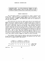
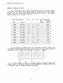
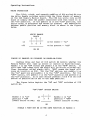
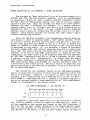
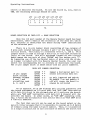
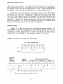
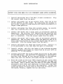
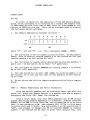
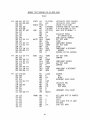
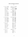
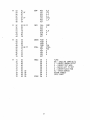
User's Manual
SuperRam(tm)
24K MEMORY MASTER(tm)
Introduction ••••••••••••••••••••••••••••••••• l
Operating Instructions ••••••••••••••••••••••• 2
Memory Addressing ••••••••••••••••••••••• 2
Memory Addressing Table ••••••••••••••••• 3
Write Protection •••••••••••••••••••••••• 4
Board Selection by I/O Address •••••••••• S
Board Selection by Data Bit ••••••••••••• 6
Phantom Enable •••••••••••••••••••••••••• 7
Summary of Switch Settings •••••••••••••• 7
Parts List ••••••••••••••••••••••••••••••••••• 8
Assembly Instructions •••••••••••••••••••••••• 9
Parts Installation •••••••••••••••••••••••••• 12
System Check-out •••••••••••••••••••••••••••• 1S
Memory Diagnostic ••••••••••••••••••••••••••• 17
Schematics •••••••••••••••••••••••••••••••••• 22
Copyr ight 1979
G. Morrow
MDRROW DESIGNS
n
5221 CENTRAL AVENUE
RICHMOND, CA 94804
(415) 524-2101
User's Manual
24K MEMORY MASTER (tm)
INTRODUCTION
The Thinke r Toys 24K Memory Master (tm) is our second entry
into the field of bank select S-100 memory products. Us ing the
popul'ar 5257 4K x 1 static RAM memory chip with an access time
which allows us to guarantee operation with 4MHz Z-80 systems and
5MHz 8085 systems, the 24K Memory Master is compatable with most
popular S-100 bank select software. This versatile be>ard can be
switched to become selected or deselected in response to any bit
ofa.ny I/O port; to come up active or inactive on power-up; and
to honor or ignore the PHANTOM bus signal. Once selected, the
unit is configured as three independently addressable and write
protectable 8K blocks, with addressing allowed at the beginning
of any8K boundary.
Of course, the 24K Memory Master also offers the reliability
and economy that come wit.h all Morrow Designs (tm), as well as
serv ice that is unmatched in the industry-- it's another Th inker
Toys product you can bank on.
1
OPERATING INSTRUCTIONS
TO AVOID ELECTRICAL DAMAGE TO YOUR 1
TURN OFF THE POWER TN YOUR 1
\ COMPUTER BEFORE INSTALLING OR REMOVING THE BOARD. ·1
1
IMPORTANT NOTE:
1 MEMORY MASTER BOARD,
MEMORY ADDRESSING
The 24K Memory Master is configured as three
blocks of 8K
bytes each.
Each block can be addressed on an 8K boundary.
Thus
a block may begin at 0000H, 2000H, 400 0H,and so forth up to the
last 8K boundary -E000H.
The addressing need not be consecutive
and may even overlap.
DIP switch 9A (at the top right hand side of the board) and
paddle #8 of DIP switch 8A are the address selection switches.
Each of these 9 paddles either grounds (when set to "on") or
pulls high (when set to "off") one input of a 74LS266 Exclusive
Nor gate.
The other input is one of the three address lines AI3
to AIS,buffered and inverted by 74LS04's. Sets of three of these
74LS266 equality gates will select their respective 8K memory
block if and only if theS-100 address lines Al3 to A15 exactly
correspond to the setting of the appropriate paddles of the DIP
switches. Thus if the ·lastthree paddles of DIP switch 9A are
all set to off, or high, then the inverted address lines 13 to 15
must also be high (meaning that the actual address lines are low)
in order to select block "C". Inth i s case, selection will only
occur when memory betwean000~H andlFFFH is being selected.
The diagram below depicts memory selection swi tches 8A and
9A and sh6ws the correspondence between the paddles and the three
8K blocks of memory which they govern.
/ BLOCK A \ / BLOCK B \ / BLOCK C \
A15 A14 A13 AlS Al4 A13 A15 A14 A13
1
1
1
1
1
1
\
1
1
\ 8 1 1
off \
\
2
3
4
5
6
7
8
on \-1-1 1 - 1 - 1 - \ - 1 - 1 - \ - \ -
position
8A
---------------9A
2
right most
switch of
top row
Operating Instructions
MEMORY ADDRESSING TABLE
The following table shows th~ relationship between swi tch
settings of the three addressing paddles controlling an8K memery
block and the starting address of that 8K block.
The tabLe
applies equally to blocks A, B, or C.
Starting Ad dress
A15
A14
A13
Corresponding
hex
binary
Hex
Octal
digi t
d igi t
1--------·1----------- ·-----1-----1-----1-----1-------1 0000 I 000:000
off 1 off 1 off I 0
1 0000
---.. . -1-----1-----1-----1-------I off I on
1
2
I
0010
I--------l-~--------1
2000
1
040:000
off
1--------1 .... ---------- ----- -----1-----1----- -------I
4000
I
100:000
of£
on
I off 1
4
0100
1--------1----------- ----- ----- ----- ----- -------I 6000 I 140:000
off
on
on
6
0l1~
1--------1----------- ----- ----- ----- ----- -------I 8000 I 200:000
on
off
off
8
1000
1--------1----------- ----- ----- ----- ----- -------1 A000
I
240:000
on
off
on
A
1010
1--------1-----------1----- ----- ----- ----- -------I C000 I 300:000 I on
on
off
C
11~0
1--------1-----------1----- ----- ----- -----1-------I E000 1 340:000 I on
on
on
E I 1110
1-------- ,1--.... --------1· -----1----- ----- -----1--------As an example of addressing the 24K Memory Master beard, the
fol1owingswi tch posi tionswill set the unit tQ the 24K of memory
starting at the secbnd 8K bQundary of memory - 2000H.
off off
on off
on off off
on
9n
I
I
I
I
I
I
II
I
I-ITI-I-I-I-I-I-'--I-I
I 8 I 1
234
5
6
781
I
I
I
SA
9A
In this example, Block A occupies memory between 2000H and
3FFFH, Block B occupies memory between 4000H and SFFFH, and Bleck
Coccupies memory between 6000H and 7FFFH.
3
operating Instructions
WRITE PROTECTrON
The fifth, sixth, and seventh paddles of DIP switch 8Aare
the Wr~t&Enable sw~tchescontrollingthe thre~blocks ofmemQry
Gn the 24KMemory Master board.
The CPU cari write into an 8K
block of memory when the paddle associated with that block is in
the "on" position.
If the paddle is in the "off n position, the
entire block is protected and cannot be altered.
The association
between paddle posi tionand. memory block is shown in the figure
bel()w.
WRITE ENABLE
BLOCK
ABC
-,-,-iI
,
,
S
6
7
write enable = "on"
off
write protect = "off"
SW 8D
COMING UP ENABLED OR DISABLED ON POWER-ON-CLEAR
Paddles three and four. of DI P swi tch 8A control whether the
Memory Master will come up active or inativeon Power-On-Clear.
Paddle 3 is the "ON" switch and paddle 4 is the "OFF" switch.
In
this case "ON" means that the board will be act iveon Po wer-OnClear (hereafter called simply POC);
"OFF" means the board will
come up inactive on POC.
For the "ON" option, set paddle 3 to
the "on" position and paddle 4 to the "off" position.
For the
"OFF" option, set paddle 3 to the "off" position and paddle 4 to
the"on" pcsition. In no case shQuld paddles 3 and4 Qf th~ DIP
switch at position 8A be set to the same position.
The fig ure below depicts the "ON"
switch8A.
and "OFF" switches of DIP
"ON"/"OFF" OPTION SWITCH
, ,
Paddle 3 in "on"
posi tion = "ON"
eboard act ive on POC)
on-'-'-
3
4
off
Paddle 4 in "on"
position = "OFF"
(board inactive on POC)
8A
PADDLE 3 MUST NOT 13E IN THE SAME POSITION AS PADDLE 4
4
Operating Instructions
BOARD SELECTION BY I/O ADDRESS -- BANK SELECTION
The purp.ose 0 f "Bank Select i on" is to allo w more memory ina
system than the CPU can normally address.
This is accomplished
by assigning a board not only a memory address somewhere within
the 64K range of addressable memory, but also an I/O port number
between 0 and 255.
Thus two boards can share the same memory
address, yet have a different I/O address.
If a system software
scheme takes care to disable one board (by outputting an
appropr iate byte. to the board's I/O port number) before enabl ing
another board (again by outputting the proper byte to its port
number), many memory boards can occupy the same memory space
without causing any conflict.
With the 24K Memory Master, two assignments must be made for
each board in order to operate under a bank select scheme. First
a n I/O po r t n urn be r mus t bed e c ide d u po n; and sec 0 n d, a d a tab i t
within that port must be chosen to act as a switch to enable the
board or disable it when a byte is written to the I/O port which
is assigned to the board. If, for example, a board is assigned
I/O port number 40H, and.further assigned data bit 0 within that
port, then the board will be activated when bit 0 of the CPU's A
register is on and an "OUT 40H" instruction is issued by the CPU.
Conversely, the same board will be disabled when the CPU executes
an "OUT 40H" instruction and bit 0 of the A register is off. (The
A reg ister is the CPU's accumulater).
In ei ther case the board
will remain selected or deselected until the CPU executes an "OUT
40H" instruction again and changes the board's selection state or
a Power-On-Cleartakes place. POC will select or deselect the
board according to the setting of paddles 3 and 4 of DI P swi tch
8A, as described above.
DIP switch 7A, the leftmost switch on the 24K Memory Master
board, controls the selection of the I/O port number to which the
board is assigned.
Paddles I through 8 on this switch may be
thought of as representing the 8 address bits of the I/O port,
with paddle 1 representing bit 7, paddle 2 representing bit 6,
and so on through paddle 8 represent ing bi t 0. Thi sass ignmen t
scheme is illustrated in the figure below.
I/O PORT ADDRESSING -- DIP SWITCH 7A
,
AD7 AD6 ADS AD4 AD3 AD2 ADI AD0
,
on
off
,
,
,
,
,
,
1-1---1---'---1---1---1---1---'-1
1 1
234
567
8 1
1
1
A paddle in the "off" position is to be taken as a cleared
bit, wh i I e a pad dIe i nth e "0 n " po sit ion set s the bit. Th us, i f
all the paddles of the switch are turned to the "off" position, 0
would be the I/Op.ort number assigned to the Memory Master board.
When all the paddles of DIP switch 7Aare in the lion" position,
255 (FF Hex or 377 Octal) is the I/O port number which is used to
5
Operating Instructions
select or deselect tbeboard. To set the board to, say, device
40R~the following settings shouYd be used.
off
on off off off off off off
I
,
,
1 ,
I
,
,
-'---1---1---1---'---1---1---11
234
567
8
7A
BOARD SELECTION BY DATA BIT -- BANK SELECTION
Once the I/O port number of the MemQry Master board has been
determined, there remains the selection . f the data bit which
will activate ()r deactivate the board during "OUT" instructions
to the selected port.
There is a 16 pin jumber block consisting of two columns of
8 pins each located between columns 6 and 7 of the Memory Master
circuit board. Vertically it straddles rows B, C,and D. This
j umpe r block is used to ass ign a data bi t to the bank selection
logic on the board.
The silk screened legend on the circuit
board names the top pair of pins "DATA0" and the bottom pair "7".
By jumpering one of the horizontal pairs of pins with the slideon jumper included with the Memory Master board, the user can
select the corresponding bit to activate or deactivate the board.
The 16 pin jumper blQck is shown below with all pairs numbered.
DATA BIT JUMPER SELECTION
16 pin jumper
block located
between col umns
6 and 7 and
stradd! ing rows
B, C, and D
DATA0
DATAl
DATA2
DATA3
DATA4
DATA5
DATA6
DATA7
* *
jumper a horizontal pair to
select activation data bit
* *
*
*
*
*
*
*
*
*
*
*
*
*
no pair jumpered and switch
. 8A paddle3en and paddle 4
off will cause the board to
always be activated
As an example, with the highest pair of pins jumpered, and
the board addressed as I/O port 40H, and "OUT 40H" instruction
with data bit. 0 set in the accumulator will activate the board,
while any "OUT 40H" instruction with data bit 0 cleared will deactivate the board.
In4ther words, an "OUT 40H" executing with,
say, a 71H inthe accumulator will select while an "OUT 40H" with
a 72H will deselect.
The fact that any bit can be used as the board select or deselect criteria means that it is pcssible to assign up to 8 banks
of memGry us ing the same I/O po r t num ber. Th us, it is pos sible
in a single instruction to turn one bank of memory off and at the
6
Operating Instructions
same time turn another on. Being able to select a bit within a
port also means that it is possible te>have as many as 2048 banks
of memory within a single 8-100 system - over a 100 MILLION bytes
of memory! This should be sufficient for most applications.
Note that, as indicated in the figure above, the 24K Memory
Master can be used as a conventional 24K memory board which pays
no attention to any I/O commands. Simply do NOT jumper any pair
of pins on the jumper block, set paddle 3 of DIP switch 8A to the
"on" position and set paddle 4 of the same switch to the "off"
position. This will cause the board to come up selected when
power is appl ied.
It will also prevent any bi t from deselecting
the board, regardless of the I/O port addressing.
PHANTOM ENABLE
Paddle I of DIP switch 8A is the Phantom Enable switch. If
this paddle is in the "on" position, the Memory Master board will
deactivate itself when PHANTOM, line 67 of the S-100 bus, is low
(asserted). When paddle 1 is on the "off" position, the Memory
Master will not respond to the PHANTOM signal on the bus.
SUMMARY OF SWITCH SETTINGS AND FUNCTIONS
I/O PORT ADDRESSING
AD7 AD6 ADS AD4 AD3 AD2 ADI AD0
I
I
1
I
1
I
I
1
on 1 - 1 - 1 - 1 - 1 - 1 - 1 - 1 - 1 - 1
I 1
234
S
6
781
I
7A
I
off I
I
PHANTOM
ENABLE
WRITE
MEMORY ADDRESSING
Ion for
/ ENABLE\ / BLOCK A \ / BLOCK B \ / BLOCK C \
I enable
A B C AlS AI4 A13 AIS AI4 Al3 AlS A14 AI3
I
1
1
1
1
I
1
I
I . I
I
I
I
1-1------------1-1-1-1-1-1-1-1-1-1-1--1-1-1
I 1
234
S
6
7
8 1 I
2
3
456
7
8 1
1
I
1
I 8A
I
9A
1
I
1
1
1
1
1
1-1-1
N.C.
I
OFF "on" deactivates board on pac
1
ON "on" activates board on POC
7
24KMEMORY MASTER PARTS LIST
print~d
1
5" x 10"
4
330 Ohm 1/4 watt resistc>rs
[
3
3.3 k Ohm SIP resistor packs
[]
18
Disk by-pass capacitors -- may vary in value from .01
to .1 microfarads depending on current supplies
[
4
1. 8
4
39 microfarad tantalum capacitors
[
3
8 position DIP switches
[
4
Heat sinks
[]
4
6-32 machine nuts & screws
[]
i
16 pin jumper block
[
1
Slide-on jumper
[
13
l4-pin low profile sockets
[
5
16-pin low profile sockets
[]
48
18-pin low profile sockets
[
4
1805 positive 5 volt regulators
[
1
74LS00 quad 2-input· NAND gate
9K
[
1
74LS02 quad 2-input NOR gate
7F
[
4
74LS04 hex inverter
[
1
74LS32 quad 2-input OR gate
7K
[
1
74LS74 dual d-type flip-flop
9H
[
1
74LSl38 1 of 8 decoder
8F
[
5
74LS266 quad Exclusive Nor gate
[
1
748288/S188/6331/82S123
[]
3
74LS367 hex Tri-state buffer
[]
48
5257 4K x 1 NMOS Static RAM
[]
mi~pofarad
circuit board wjsilk screen legend
tantalum capacitors
4K, SK, 6K, 9F
8
8 x 32 PROM
78,8B,98,70,90
80
7H,8H,8K
18 through 6J
ASSEMBLY INSTRUCTIONS
WARNING! IMPROPER ASSEMBLY OF THIS KIT WILL VOID
THE WARRANTY. READ THESE INSTRUCTIONS CAREFULLY
BEFORE ATTEMPTING TO CONSTRUCT THIS KIT
INVENTORY
Make sure that all the parts listed in the PARTS LIST have
been included.
Notify Thinker Toys immediately if any parts are
missing. Also, quickly return all extra parts.
USE SOCKETS
Sockets are provided for every IC on the 24K Memory Master.
NO REPAIR WORK WILL BE PERFORMED ON ANY RETURNED
BOARD WITH ANY IC SOLDERED DIRECTLY TO THE CIRCUIT BOARD
ORIENTATION
When this manual refers to the bottom of the circuit board,
it means the edge with the gold S-100 edge connec~ors. Right and
left assume a view from the component side of the board which has
the silk screened parts legend embossed over the solder mask.
All IC sockets have their pins numbered, have a 45 degree
angle across the corner of pin one, or have a notch at the end
which indicates pin one. On the 24K Memory Master, all sockets
and all ICshave pin 1 closest to the bottom left corner of the
circuit board.
The 1.8 and 39 microfarad tant.al um capaci tors are polar i zed.
The 1.8 microfarad capacitor's positive end is identified by a
circular "ti t"where . the lead enters the body of. the housing.
A
red band identifies the positive end of the 39 microfarad device.
The legend on the circuit board identifies the positive lead of
these axial parts with a "+" sign.
The by-pass capacitors, which
are· identified on the legend by an asterisk "*11 enclosed by an
oval, are not polarized.
The three DIP switch arrays are to be positioned so that the
letters and numbers stamped on them are right side up -- that is,
paddle 1 should be to the left and paddle 8 on the right.
9
Assembly Instructions
The SIP resistor packs, historically prone to being inserted
backwards, should have their orienting dot nearest the white dot
on the legend of the board. On the 24K Memory Master beard, this
turns out to be to the left for all three SIP packs.
EXAMINE THE BOARD
Visually examine the circuit board for any trace opens or
shorts. A concentrated five minute scrutiny will uncover most
trace defects.
Several hours of scattered, unconcentrated work
generally wGn't reveal anything.
Take special care that no short
or opens exist on those areas of the circuit board that will be
covered by Ie sockets. Ohm out any suspicious looking traces for
either shorts or discontinuity as appropriate. Return at once
any bare board found to be flawed.
Such bGardswill be replaced
under warranty.
SOLDERING AND SOLDER IRONS
The most desirable soldering tool for a complex electronic
kit is a constant temperature iron with an element regulated at
650 degrees F. The tip should be fine so that it can be brought
into close contact with the pads of the circuit board. This type
of soldering iron is available from Weller or Unger (to name just
two) and should be a part of any electronics shop.
There are three important soldering rules that should be
follGwed when building this kit:
1. DG not use an iron that is too cold (less than 600
degrees F.) or too hot (more that 750 degrees F.).
2.
Do not hold the iron against a pad for mGre than
about six seconds at a time.
3.
Do not apply excessive am.unts of solder.
The recommended pr0cedure for solder ing components to the
circuit board is as follows:
1. Sr ing the iron in contact with BOTH the componen t
lead AND the pad.
2. Apply a SMALL amount of solder at the point where
the iron, component lead, and the pad ALL make contact.
10
Assembly Instructions
3.
After the initiala~plicati()niofsolderand when it
has flQwed to the pad and component lead, the heat of
the iron will have transferred to BOTH the pad AND the
lead.
Apply a small amount cfadditicnal solder to
cover the jQ intbetween the pad and the lead.
DO NOT
PILE SOLDER ON THE JOINT!
EXCESSIVE HEAT AND SOLDER
CAUSE P.ADS AND LEADS TO LIFT FROM THE CIRCUIT BOARD.
ALSO, EXCESSIVE SOLDER I S THE PRIMARY CAUSE FOR BOARD
SHORTS AND BRIDGED CONNECTIONS.
11
PARTS INSTALLATION
I
I
I
I
IPROTECT YOUR EYES WHEN YOU CLIP COMPONENT LEADS AFTER SOLDERING I
Install and solder the 4 330 Ohm 1/4 watt resistors.
the excess leads from the parts.
Clip
[]
Install and solper the 18 pin sockets first, then the 16 and
14 pin sockets in that order.
By installing the sockets in
this order, a smaller sized socket will never be placed in a
larger sized position.
[
Install and solder the three SIP resistor packs. Be careful
that the orienting dots are pointing to the left.
[]
Install and solder the 4 axial lead 1.8 microfarad tantalum
capacitors.
The circular "tit" identifying the positive end
is to face toward the bottom of the circuit board when the
part is installed. Clip the excess leads from the parts.
[]
Install and
capacitors.
face towa rd
installed.
solder the 4 axial lead 39 microfarad tantalum
The red band identifying the positive end is to
the bottom c>f the c i rcui t board when the pa rt is
Clip the excess leads from the parts.
Install and solder the three DIP switch arrays. Switch 1 is
to be positioned to the left when the part is installed.
[]
Install, solder, and clip the leads of the eighteen by-pass
capacitors whese positions are identified by an oval with an
asterisk "*" in the middle.
[]
Install and solder the 16 pin jumper block just to the right
of the RAM array. Its position is marked bya rectangular
outline with "DATA0" at the top and "DATA7" at the bottom.
Make sure that the shorter pins pass thrc>ugh the board.
[]
Bend the leads of the four 7805 regulators and insert them
in the circuit board. Place a heat sink between the 7805 and
the board.
Work a screw from the back of the board through
the board, heat sink, and regulator in that order and hand
tighten onto a nut at the top of the regulator. Solder the
leads and adjust the heat sinks so that they are square with
the board. Finally, tighten the nut and screw.
12
Parts Installation
CLEAN AND EXAMINE THE BOARD
Use fl·uxcleaner to remove solder rosin residue. Examine
the circuit board carefully for shorts, solder bridges, or pins
on sockets that have not been soldered.
HOW TO FIND WHERE TO PLACE PARTS
For parts placement, please see the silk screened legend on
the printed circuit board. ICs may vary from thQse marked on the
legend if they are listed as alternate ICs (following a slash) in
the Parts List.
DO NOT INSERT ANY INTEGRATED CIRCUITS AT THIS TIME
Before inserting any IC in its socket, the following checkout procedure must be performed:
1.
Re-check the back of the circuit board for solder shorts
and bridged connections and for pins of Ie sockets that have
not been soldered. These unsoldered pins can cause problems
which are often intermittant and usually hard to find.
2. Re-check components for orientation. Also make sure all
components tQ be soldered have been soldered.
3.
With an Ohm Meter., check for shorts between the +5 Volt
lead of the 7805 regulators and ground.
The output pins of
the regulators are on the right side of the part. Check for
$hor.ts betweenS-100 pin 1 or 51 (+8V) and ground.
On the
S-100 bus, ground is on pins 50 and 100.
4.
Place the board WITHOUT ICs into a bus slot of an other~
wise empty system and power up the system. Incase of smoke
power down immediately and investigate.
5. With a VOM Grscope, check the regUlators for +5V. Next,
check for +5V and grQundon all IC sockets. If everything
is OK, power down and proceed to IC insertion.
IC INSERTION
If an IC insertion tool is not available, IC leads should be
straightened a ROW at a time, not by the individual PI~. An edge
of a stright sided table is an excellent device for this purpose.
Hold the Ie by the plastic case, place one row of legs against a
flat surface and push very slightly. Repeat with the oPPQsite
row. Continue this procedure until the legs of the ICcan be put
into its socket with a minimum of effort.
13
Parts Installation
When the IC is inserted intQ its socket, take care that Qne
or more pins are NOT BENT UNDERNEATH ITS PLASTIC PACK.
This is a
very common occurance and can escape even a fairly careful visual
inspection. BENT ICPINS ARE THE MOST COMMON BOARD FAULT IN KITS
THAT ARE BUILT IN THE FIELD!
If IC pins are bent under the pack during insertion, use a
pair of long nose pliers to straighten them and try again.
When
an IC must be removed from its sQcket, use an IC remover, a test
clip (another must for any electronics shop), or a small enough
screw d river s G that its blade can f it between the plastic case
of the IC and the socket. DO NOT ATTEMPT TO REMOVE AN IC WITH
YOUR FINGERS. Very often the pins will bend and cut a finger as
the IC pops out of its socket.
On c e the I Cs h ave be e n ins e r ted, c he c k 0 n c e a g a i n for ben t
pins.
Then check twice that all the ICs have been inserted into
their sockets with the proper orientation - pin 1 must be pointed
tQward the lower left of the circui t board.
Upside down ICs are
usually destroyed upon power up.
IF FOR ANY REASON IT BECOMES NECESSARY TO REMOVE A
PART THAT HAS BEEN SOLDERED TO THE CIRCUIT BOARD,
CLIP ALL THE LEADS OF THE PART BEFORE REMOVING.
THIS WILL REDUCE THE CHANCE OF LIFTING PADS.
POWER UP
If all previous checks have been performed, YGU are ready to
put power to your fully populated board.
In an empty system with
PQwer off, insert the Memory Master and power up. If the board
smokes, power down immediately and investigate.
If not, measure
the regulated voltages once again.
If any of the voltages have been lost since powering up the
bare board, power down and check for upside down Ies.
Isolate
the PQ s sib 1 e fa u 1 t Y chi P 0 r chi P s by power i ng down, rem 0 v in g a
section of ICs and powering up again.
Continue this sequence
until the faulty IC or ICs are found.
BE SURE NEVER TO INSERT OR REMOVE A BOARD
WITH POWER ON!
THIS MAY DAMAGE THE BOARD
This completes the initial check-out of your Memory Master.
14
SYSTEM CHECK-OUT
STATIC TEST
Set up
In order to check-out the operation of the 24KMemory Master
board, first configure it to function as a simple 24K memory that
is addressed as the first 24K of RAM, that is, from 0033H at the
bot t em to SF F FHa t the top. Th i s can be a c co mp lis he d by ma kin g
the following switch settings:
1.
Set Memory Addressing switches as below
F
,
F
I
F
1
F
,
F
,
, 8 '1
off'
,
2
3
456
on
=
F
,
N
,
F
1
'-'-'-'-1-'-'-'-'-'--'-'
off and "N"
78'
I
9A
8A
where "F"
N
,
=
on.
This represents 3000H - 5FFFH.
2. Set the boa rd to ON (to appea r act ive on POC). As discussed
above, this is done by turning paddle 3 of DIP switch 8A "on" and
turning paddle 4 of DIP switch 8A "off"
3. Set the board to enable write 0perations by placing paddles 5
and 6 and 7 of DIP switch 8A to their "cn" pt>sitions.
4. Set the board to ignore PHANTOM by turning paddle 1 of switch
8A to the "off" position.
5.
Set the board to I/O port 40H (100Q) by setting paddle 2 of
DIP switch 7A to "Gn" and the rest of the paddles of DIP switch
7A to "off"
6. Do not place the sJ id-on jumper anywhere on the 16 pin jumper
block.
TEST 1:
Memory Addressing and Write Protection
With the switch paddles set .as indicated above and with the
pt>wer off, place the Memory Master ina system that has. no memory
Gccupyingthe first 24K. Power the system up.
With a front panel (one that MUST generate the S-100 status
s ig na I SW a d ur ing mern 0 r y de po sit s) 0 r amon ito r, exam in e 1 oca t ion
0000H, write 00H in this location, and re-examine it to be sure
that it nGwcontains a 00. N0wdep0sit FFH (377Q) in this same
location and read it back. Now set paddle 5 of DIP switch 8Ato
"off", and attempt to change the FF in location 0000H to another
number -- you should not be able to alter this location now. Set
15
System Check-out
paddle 5 of 8A back to "on". Verify that location 0000H can once
again be altered.
Repeat the above procedure first at location
2000H using paddle 6 of 8A and then again at location 4000H with
paddle 7 of SA.
TEST 2:
Bank Selection
Place the slide-on jumper across the two pins labled DATA0
on the 16 pin jumper block. With a 0 in the CPU's accumulator,
execute an "OUT 40H" command. You should now have lost access to
the Memory Master board. Now execute an "OUT 40H" command wi th a
1 in the CPU's accumulator. The Memory Master should now be once
againaccessable.
TEST 3:
POC - ON/OFF
With a jumper still across DATA0 of the 16 pin jumper block,
make sure that you can still access the board.
Now turn off the
power and back on again and again verify that the board can be
accessed. Next, on DIP switch 8A, turn paddle 3 "off" and turn
paddle 4 "on". Power down and power back up again. The Memory
Master should be disabled.
Execute an "OUT 40H" instruction with
a 1 in the CPU's accumulator.
This should reactivate the Memory
Master.
This completes the static system tests.
contain a full fleged memory diagnostic.
16
The following pages
MEMORY DIAGNOSTIC
The memory test described below was designed by Phil Meads of
William Brobeck Associates to exercise the most sensitive circuitry of
the memory chips -- the address buffers. The test starts from the middle
and works its way outward alternately to the top and bottom of memory.
This type of test inverts the address lines more often than sequential
ones. This continual inversion process punishes and eventually breaks
down weak or faulty address buffers in the device.
USING THE TEST
The test itself must be placed in an area which is different than the
location of the board~to be tested. The test starts on a page boundary
to make the task of -relocating the binary code easier.
There are two parameters in the test to be set by the user:
(1)
The number -of 4K blocks to be tested -- keep in mind that
there are four 4K blocks per board. This constant is called
BLKCNT and is located at the eleventh byte of the test.
(2)
The starting ~ number of the. lowest 4K block to be tested
is called PAGENO and is located at the ninth byte of the test.
When testing more than one 4K block of memory, be sure that they
occupy contiguous memory.
The page number of the position of the test itself must be entered
wherever a (YYY)s or (YY)16 occurs in the test listing. This is necessary
because JMP and CALL need both the page number and the location within the
page to execute correctly.
The only other thing to remember when loading the test is that it must
be placed at the starting address of a page.
Start the test at the first instruction. Once started, the test will
run continuously unless an error is detected. If the test encounters an
error, all the data pertinent to this error is stored in the last ten
locations of the test. After storing this data, the test comes to a dynamic
halt at the label STALL. The test may be restarted by stopping the computer
and restarting it at the POP PSW instruction following JMP STALL. The user
may also restart the test from the beginning. If errors indicate the board
is malfunctioning, return it as soon as possible for service.
17
MEMORY TEST PROGRAM FOR 4K NMOS RAMS
Octal
YYY 000 061
003 001
006 305
007 006
011 016
013 041
016 .170
017 204
020 147
021 345
022 315
025 167
026 315
031 315
034 167
035315
040 302
043 341
YYY 044
047
050
053
056
061
062
065
070
315
256
304
315
315
256
304
315
302
YYY 073
075
076
077
100
103
104
106
107
110
111
076
200
107
015
302
173
306
137
301
003
303
114
115
116
117
120
121
122
175
007
207
204
203
127
311
175 YYY
000 000
100
004
377 007
114 YYY
123 YYY
114 YYY
134 YYY
022 YYY
114 YYY
145 YYY
123 YYY
114 YYY
145 YYY
134 YYY
044 YYY
020
013 YYY
207
006 YYY
START LXI
LXI
NEWCYL PUSH
MVI
MVI
LOOP LXI
MOV
ADD
MOV
PUSH
WRITE CALL
MOV
CALL
CALL
MOV
CALL
JNZ
POP
SP,STACK
B,O
B
B,PAGENO
C,BLKCNT
H,7:377Q
A,B
H
H,A
H
TWORD
M,A
COMP
TWORD
M,A
INCR
WRITE
READ
CALL
XRA
CNZ
CALL
CALL
XRA
CNZ
CALL
IN.z
TWORD
M
ERROR
COMP
TWORD
M
ERROR
INCR
READ
MVI
ADD
MOV
OCR
JNZ
MOV
ADI
MOV
POP
INX
JMP
A,20Q
B
B,A
C
LOOP
A,E
135
E,A
B
B
NEWCYL
ADVANCE
THE
BLOCK
DECREMENT BLOCK COUNT
A,L
GET LOWER BYTE OF ADDRESS
ROTATE
SHIFT
ADD HIGHER BYTE OF ADDR
ADD BASE
SAVE TEST WORD
H
TWORD MOV
RLC
ADD
ADD
ADD
MOV
RET
A
H
E
D,A
18
INITIALIZE STACK POINTER
INITIALIZE CYCLE COUNT
UPDATE CYCLE COUNT
STARTING ADDR OF TEST MEM
# OF 4K BLOCKS TO TEST
HALF SIZE OF MEMORY -1
CALCULATE MIDDLE
OF CURRENT BLOCK
SAVE INITIAL ADDRESS
GET TEST WORD
STORE
COMPLEMENT ADDRESS
GET TEST WORD
STORE
COMPLEMENT & DECREMENT
ADDRESS
RECOVER INITIAL ADDRESS
GET TEST WORD
COMPARE
COMPLEMENT ADDRESS
GET TEST WORD
COMPARE
COMPLEMENT & DECREMENT
ADDRESS
CALCULATE NEW
BASE FOR
TEST WORD
INCREMENT CYCLE COUNT
YYY 123
124
126
127
130
132
133
174
356 017
147
175
356 377
157
311
COMP
MOV
XRI
MOV
MOV
XRI
MOV
RET
A,H
17Q
H,A
A,L
377Q
L,A
COMPLEMENT THE UPPER
BYTE ADDRESS
WITH RESPECT TO MEM SIZE
COMPLEMENT THE LOWER
BYTE OF THE
ADDRESS
YYY 134
137
140
141
142
143
144
315 123 YYY
053
300
170
075
274
311
INCR
CALL
DCX
RNZ
MOV
OCR
CMP
RET
COMP
H
RESTORE ADDR TO NORMAL SIZE
DECREMENT
TEST IF LOWER BYTE ZERO
TEST UPPER BYTE EQUAL
TO BLOCK
BOUNDARY
YYY 145
146
147
150
151
154
155
156
157
160
345
305
325
365
303 151 YYY
361
321
301
341
311
ERROR PUSH
PUSH
PUSH
PUSH
STALL JMP
POP
POP
POP
POP
RET
H
B
TABLE
DB
DB
DB
DB
DB
DB
OW
OW
0
0
0
0
STACK OW
a
YYY 161000
162 000
163 000
164 000
165 000
166 000
167 000
171 000
173 000
175 000
000
000
000
000
A,B
A
H
0
PSW
STALL
PSW
0
B
H
a
a
a
a
a
ow
19
SAVE ERROR ADDRESS
SAVE CURRENT BLOCK
SAVE TEST WORD
SAVE ERROR BITS
DYNAMIC HALT
RESTORE
THE
STATE OF
THE CPU
FLAGS
ACC - ONES ARE ERROR BITS
E - CURRENT RANDOM OFFSET
o - CURRENT TEST WORD
C - CURRENT BLOCK COUNT
B - CURRENT BLOCK PAGE
HL - ERROR ADDRESS
RETURN ADDRESS
CYCLE COUNT
MEMORY TEST PROGRAM FOR 4K NMOS. RAMS
Hex
YY 00
03
06
07
09
OB
OE
OF
10
11
12
15
16
19
lC
10
20
23
31
01
C5
06
OE
21
78
84
67
E5
CD
77
CO
CD
77
CD
C2
El
YY 24
27
28
2B
2E
31
32
35
38
CD
AE
C4
CD
CD
AE
C4
CD
C2
YY 3B
3D
3E
3F
40
43
44
46
47
48
49
3E
80
47
00
C2
7B
C6
5F
Cl
03
C3
YY 4C
40
4E
4F
50
51
52
70
07
87
84
83
57
C9
70 YY
00 00
40
04
FF 07
4C YY
53 YY
4C YY
5C YY
12 YY
4C YY
65 YY
53 YY
4C YY
65 YY
5C YY
24 YY
10
OB YY
87
06 YY
SP,STACK
8,0
8
8,PAGENO
C,BLKCNT
H,7:377Q
A,B
START LXI
LXI
NEWCYL PUSH
MVI
MVI
LOOP LXI
MOV
ADD
MOV
PUSH
WRITE CALL
MOV
CALL
CALL
MOV
CALL
JNZ
POP
H,A
H
TWORD
M,A
COMP
TWORD
M,A
INCR
WRITE
H
CALL
XRA
CNZ
CALL
CALL
XRA
CNZ
CALL
JNZ
TWORO
M
ERROR
COMP
TWORD
M
ERROR
INCR
READ
READ
H
A,20Q
MVI
ADD
MOV
OCR
JNZ
MOV
ADI
MOV
POP
INX
JMP
B
B,A
C
LOOP
A,E
135
E,A
B
B
NEWCYL
A,L
TWORD MOV
RLC
ADD
ADD
ADD
MOV
RET
A
H
E
D,A
20
YY 53
54
56
57
58
5A
58
7C
EE OF
67
70
EE FF
6F
C9
COMP
MOV
XRI
MOV
MOV
XRI
MOV
RET
A,H
17Q
H,A
A,L
377Q
L,A
YY 5C
5F
60
61
62
63
64
CD 53 YY
28
CO
78
3D
BC
C9
INCR
CALL
DCX
RNZ
MOV
DCR
CMP
RET
COMP
H
YY 65
66
67
68
69
6C
6D
6E
6F
70
E5
C5
D5
F5
C3 69 YY
Fl
D1
C1
E1
C9
ERROR PUSH
PUSH
PUSH
PUSH
STALL JMP
POP
POP
POP
POP
RET
YY 71
72
73
74
75
76
77
79
78
70
00
00
00
00
00
00
00
00
00
00
TABLE DB
DB
DB
DB
DB
DB
OW
OW
OW
STACK OW
00
00
00
00
A,8
A
H
H
8
D
PSW
STALL
PSW
0
8
H
0
0
0
0
0
0
0
0
0
0
21
FLAGS
ACC - ONES ARE ERROR BITS
E - CURRENT RANDOM OFFSET
D - CURRENT TEST WORD
C - BLOCKS LEFT TO TEST
B - CURRENT BLOCK PAGE
HL - ERROR ADDRESS
RETURN ADDRESS
CYCLE COUNT