1
"MiniRFE-1G"
Miniaturized High-Sensitivity Optical
InGaAs APD Receiver Frontend for
Free-Space Gigabit-Ethernet Data Reception
Manual
© ViaLight Communications GmbH
Friedrichshafener Straße 1, 82205 Gilching, Germany
www.vialight.de
1 - 12
Title of this Document:
MiniRFE-1G Manual
Document name:
MiniRFE-1G_Manual.odt
Author:
D. Giggenbach
Document start:
2. January 2011
Last change:
19. January 2011
Version No.:
V0.1
Document content:
User manual, technical description, and performance
measurements of four high-sensitivity InGaAs APD
receiver frontends with housing
Change history:
V0.1: first version of this manual
Content
Summary of Technical Data.........................................................................................................2
Functional Description of MiniRFE-1G......................................................................................3
Getting Started.............................................................................................................................4
Interfaces and Controls - µControler-PCB...................................................................................5
Interfaces and Controls - HF-PCB...............................................................................................6
Typical Signals on the Oscilloscope ............................................................................................7
Typical Performance....................................................................................................................8
Graphical User Interface..............................................................................................................9
RS232-Cable................................................................................................................................10
Housing Drawings........................................................................................................................12
Advices.........................................................................................................................................13
Summary of Technical Data
Parameter
Unit
Value
nW
250
1.25Gbps, BER=1E-6, PRBS=2^7-1
Typical minimum optical power
nW
100
1.25Gbps, BER=1E-3, PRBS=2^7-1
Maximum optical power
µW
50
damage may occur above, not tested
InGaAs-APD diameter
µm
200
usable wavelength
µm
1 .. 1.7
V
5.5 ... 7
Supply current typical
mA
390
Size
mm
60 x 40 x 38
g
143
335
Typical sensitivity (mean Rx-power)
Supply voltage
weight
alumnium
V2A
2 - 12
Condition
use lowest possible supply voltage to avoid unnecessary
heating of receiver module (reduces sensitivity)
all outputs terminated with 50R
housing, and assembled PCB, without any cables
Functional Description of MiniRFE-1G
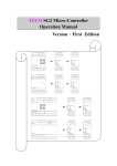
The MiniRFE-1G comprises a high-sensitive differential InGaAs-APD receiver frontend with a
micro-controller for temperature compensated high-voltage (HV) regulation and digital interfacing
via RS-232. Every devide is individually temperature calibrated. The device can be controlled from
a Windows Graphical User Interface (GUI) or it can be used stand-alone in automatic HV-control
mode. In manual control mode, the APD-voltage can be set via the GUI.
The InGaAs-APD is connected to a transimpedance amplifier which converts the photo current into
a voltage signal. This signal is AC-coupled and low-pass filtered for noise-reduction and amplified
with an amplifier that features two differential output ports. One differential output pair can be
monitored as „AUX-Out“ and so allows direct control of the received signal amplitude and quality.
This AUX-out can be dissabled to save power. The other differential amplifier output is converted
by a limiting amplifier to standard differential 50R PECL outputs.
A LOS-signal (Loss-Of-Signal) is provided as SMA-output, indicated by a red LED and via the
digital interface. A squelch-functionality ("PECL signals off" during LOS) can be selected via the
GUI.
The PCB was produced compliant to RoHS.
High-Frequency (HF) Board Diagram
Microcontroller (uC) Board Diagram
3 - 12
Getting Started
Stand-Alone Mode:
•
mount device with APD in focus of the optical intensity-modulated data signal
•
connect HF-BU1 to Oscilloscope (terminate with 50R) to observe analog signal quality
•
connect HF-BU4 to digital data receiver, terminate with 50R
•
connect HF-BU5 to high-impedance signal input to observe LOS-state
•
terminate all unused SMA-plugs with 50R except for LOS-out (is high-impedance)
•
connect +6V / 500mA DC power supply to BU2 (best to use laboratory power supply)
•
µC will boot and signal-output starts after ~1s, LD3 blinks once per second
with GUI-Control:
•
execute all steps as described above
•
connect RS232-Interface to a PC
•
unpack all files of „GUI.zip“ into one directory and start „GUI.exe“
•
select correct RS232 port number in GUI, press „open“
•
check the description of the GUI
4 - 12
Interfaces and Controls – µController-PCB (uC)
View onto the rear PCB „uC“ (BackSide cover with the LED-ports removed)
Element
Name in Schematic
Power
BU2
voltage supply input 5.5V..7V, typical: ~6V, ~400mA
for connector type: power supply plug, e.g. Lumberg 1636 01
for plug with inner hole diameter: 0.7 mm, outer diameter: 2.35mm
RS232-interface
BU4
connect to PC via custom RS232-Cable (connector is type 4-wire Firewire)
HV-ctrl jumper
J2
A: control HV manually via TR1
B: control HV via µC or from PC via RS232 (default)
manual HV-ctrl
TR1
sets HV manually when J2-A; turn left to increase HV
accessible via hole in the housing
Test Point 1
TP1
measure APD-HV here
PGM-connector
ST1
connector to flash new µC-Software
RS232-data
LD1
on when RS232 is sending data to PC
LD2
µC-error, red
LD3
µC-alive signal
LD4
on when LOS , yellow
LD5
power-supply on, green
LD6
VCC-5.0V Okay, green
LD7
VCC-3.3V Okay, green
5 screw holes
Function
make sure to connect the GND-layer to the housing and to the HF-PCB via
the screws at the bottom of the PCB
5 - 12
Interfaces and Controls – High-Frequency-PCB (HF)
View onto the APD-side PCB „HF“ (FrontSide housing removed)
Element
Name in Schematic
AUX-OUT(+)
BU1
analog monitoring output
AUX-OUT(-)
BU2
analog monitoring output
DIG-OUT(-)
BU3
negative PECL-out
DIG-OUT(+)
BU4
positive PECL-out
!LOS-signaling
BU5
high (~1V) when a sufficient signal level is detected, terminate into >10kR
Offset-Jumper
J2
detector
SEN1
BEF1..4
Function
controls internal Offsets, needs to be set to „B“ (left)
InGaAs-APD, 200µm diameter
screw connectors for GND to housing and uC-PCB
6 - 12
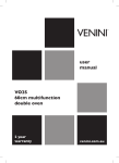
Typical Signals as seen on Oscilloscope
Typical Output Signals with (upper) PRx=2µW and (lower) PRx=250nW,
datarate is 1.25Gbps with PRBS 2^7-1 (all lines terminated into 50R)
upper channel: positive analog out (HF-BU1), 50mV/ in upper picture, 20mV/ in lower
second channel: negative analog out (HF-BU2), 50mV/ in upper picture, 20mV/ in lower
lower channel: negative PECL-out (HF-BU3), 200mV/ in both pictures
7 - 12
Typical Performance Measurements of MiniRFE-1G
All measurements with 1.25Gbps, PRBS=27-1, wavelength=1550nm
8 - 12
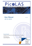
Graphical User Interface
Screenshot of the Graphical User Interface for the MiniRFE-1G
The Graphical User Interface can be used under Windows XP/Vista/7. To install the GUI, the
supplied archive-file must be extracted. Subsequent to this step, the GUI can be started by running
the contained executable file. Please note that also library files are supplied within the archive file.
Without these libraries, the GUI might not be able to run.
The connection to a MiniRFE-1G can be initiated by selecting a proper Serial Port, followed by a
click on the „Open“ Button. All relevant functionalites of the MiniRFE-1G can be controlled via the
GUI. This includes:
•
Flags
Enable/Disable Squelch Functionality
Enable/Disable Auxiliary Signal Output
Enable/Disable High Voltage Module
Automatic/Manual Control of High Voltage
•
High Voltage Control (Manual Mode Only)
In case the MiniRFE-1G is operated in manual High-Voltage Control Mode, the High
Voltage can be selected here
•
Status
A green light indicates if the given value is activated or not.
•
Measured Values
9 - 12
A Number of values are displayed in this section:
U_APD / V
Voltage measured at the Avalanche Photodiode
I_APD / µA
Photocurrent of the Avalanche Photodiode
HV / V
High Voltage at the Output of the High-Voltage Generation Module
Temp / °C
APD-Temperature in Degrees Celsius
Vcc 3.3V / V Current Status of 3.3V Supply Voltage
Vcc 5.0V / V Current Status of 5.0V Supply Voltage
RS232-Cable (Firewire Connector)
A Standard Firewire-Connector is used on the PCB to connect the MiniRFE-1G via RS232 to a PC.
The MiniRFE-1G is supplied with a cable converting the firewire-connector to a standard Sub-D-9
RS232 Connector.
1 - Ground
2 - RXD
3 - TXD
4 - NC
Pinout of the Firewire Connector
Direct Control via a standard RS232 Terminal Programm
The parameters of the MiniRFE-1G visible in the GUI can also be accessed over a standard terminal
program. The terminal program needs to be set up with the parameters: 9600baud, 8 Databits,
1 Stopbit, No FlowControl. After initiating the connection, a self-explaining clear text output is
provided.
Please note that it is not recommended to use a standard terminal program to directly access the
MiniRFE-1G's parameters, as this mode of operation allows the adjustment of parameters that were
preset in the factory for optimum performance. Programming wrong parameters can damage the
APD through obvervoltage. Do use the provided GUI instead. The MiniRFE-1G has been optimized
in a way that all specifications are guaranteed over the full temperature range, and under normal
operation conditions an adjustment of these parameters is not necessary.
Thus it is recommended to use the GUI for normal operation of the MiniRFE-1G.
10 - 12
Housing
FrontSide
MiddlePart
11 - 12
BackSide
Advices / Remarks
•
The RFE is optimized for a data rate of 1.25Gbps. Serial data between 125Mbps and
1.4Gbps can be received in general but at lower photons-per-bit sensitiviy.
•
The AUX-Out-amplitude does not rise linearly to the received power due to the currentlimiting HV-supply circuit which protects the APD from photo current overload.
•
If available, the device should be used with a good quality laboratory power supply at 6V /
450mA. With a small wall power supply, the sensitivity might decrease due to increased
supply voltage ripple.
•
terminate all unused signal-outputs into 50R (but not BU5, which is high-impedance and
shall be left open when not used)
Abbreviations
APD Avalanche Photo Diode
HV
High Voltage (for APD)
HF
High-Frequency-PCB
uC
Micro-Controller-PCB
µC
Micro-Controller
PCB
Printed Circuit Board
12 - 12