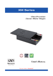
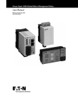
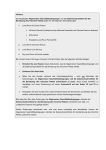
1
Power Xpert inControl
User Manual
Effective June 2014
New Information
Power Xpert inControl
Disclaimer of Warranties and Limitation of Liability
The information, recommendations, descriptions and safety notations in this document are
based on Eaton Corporation’s (“Eaton”) experience and judgment and may not cover all
contingencies. If further information is required, an Eaton sales office should be consulted.
Sale of the product shown in this literature is subject to the terms and conditions outlined in
appropriate Eaton selling policies or other contractual agreement between Eaton and the
purchaser.
THERE ARE NO UNDERSTANDINGS, AGREEMENTS, WARRANTIES, EXPRESSED OR
IMPLIED, INCLUDING WARRANTIES OF FITNESS FOR A PARTICULAR PURPOSE OR
MERCHANTABILITY, OTHER THAN THOSE SPECIFICALLY SET OUT IN ANY EXISTING
CONTRACT BETWEEN THE PARTIES. ANY SUCH CONTRACT STATES THE ENTIRE
OBLIGATION OF EATON. THE CONTENTS OF THIS DOCUMENT SHALL NOT BECOME
PART OF OR MODIFY ANY CONTRACT BETWEEN THE PARTIES.
In no event will Eaton be responsible to the purchaser or user in contract, in tort (including
negligence), strict liability or otherwise for any special, indirect, incidental or consequential
damage or loss whatsoever, including but not limited to damage or loss of use of equipment,
plant or power system, cost of capital, loss of power, additional expenses in the use of
existing power facilities, or claims against the purchaser or user by its customers resulting
from the use of the information, recommendations and descriptions contained herein. The
information contained in this manual is subject to change without notice.
Cover Photo: Power Xpert inControl.
Power Xpert inControl MN040013EN—June 2014
www.eaton.com
i
Power Xpert inControl
Support Services
The goal of Eaton is to ensure your greatest possible satisfaction with the operation of our
products. We are dedicated to providing fast, friendly, and accurate assistance. That is why
we offer you so many ways to get the support you need. Whether it is by phone, fax, or
email, you can access Eaton’s support information 24 hours a day, seven days a week. Our
wide range of services is listed below.
You should contact your local distributor for product pricing, availability, ordering, expediting,
and repairs.
Website
Use the Eaton website to find product information. You can also find information on local
distributors or Eaton’s sales offices.
Website Address
www.eaton.com/drives
EatonCare Customer Support Center
Call the EatonCare Support Center if you need assistance with placing an order, stock
availability or proof of shipment, expediting an existing order, emergency shipments, product
price information, returns other than warranty returns, and information on local distributors or
sales offices.
Voice: 877-ETN-CARE (386-2273) (8:00 a.m.–6:00 p.m. EST)
After-Hours Emergency: 800-543-7038 (6:00 p.m.–8:00 a.m. EST)
Drives Technical Resource Center
Voice: 877-ETN-CARE (386-2273) option 2, option 6
(8:00 a.m.–5:00 p.m. Central Time U.S. [UTC –6])
email: [email protected]
For Customers in Europe, contact:
Phone: +49 (0) 228 6 02-3640
Hotline: +49 (0) 180 5 223822
email: [email protected]
www.eaton.com/moeller/aftersales
ii
Power Xpert inControl
MN040013EN—June 2014
www.eaton.com
Power Xpert inControl
Table of Contents
SAFETY
Definitions and Symbols . . . . . . . . . . . . . . . . . . . . . . . . . . . . . . . . . . . . . . . . . .
Hazardous High Voltage . . . . . . . . . . . . . . . . . . . . . . . . . . . . . . . . . . . . . . . . . . .
Power Xpert Safety . . . . . . . . . . . . . . . . . . . . . . . . . . . . . . . . . . . . . . . . . . . . . .
Before Using the Software Tool . . . . . . . . . . . . . . . . . . . . . . . . . . . . . . . . . . . . .
Warnings and Cautions . . . . . . . . . . . . . . . . . . . . . . . . . . . . . . . . . . . . . . . . . . .
Personnel Safety . . . . . . . . . . . . . . . . . . . . . . . . . . . . . . . . . . . . . . . . . . . . . . . .
v
v
v
v
v
v
INTRODUCTION
Using This Manual . . . . . . . . . . . . . . . . . . . . . . . . . . . . . . . . . . . . . . . . . . . . . . .
Power Xpert inControl System Overview . . . . . . . . . . . . . . . . . . . . . . . . . . . . .
FDT/DTM Explanations . . . . . . . . . . . . . . . . . . . . . . . . . . . . . . . . . . . . . . . . . . .
Benefits of FDT/DTM Systems . . . . . . . . . . . . . . . . . . . . . . . . . . . . . . . . . . . . .
1
1
2
2
INSTALLATION INSTRUCTIONS
System Requirements . . . . . . . . . . . . . . . . . . . . . . . . . . . . . . . . . . . . . . . . . . . .
Installation Procedure . . . . . . . . . . . . . . . . . . . . . . . . . . . . . . . . . . . . . . . . . . . .
Uninstall Procedure . . . . . . . . . . . . . . . . . . . . . . . . . . . . . . . . . . . . . . . . . . . . . .
Software Update Procedure . . . . . . . . . . . . . . . . . . . . . . . . . . . . . . . . . . . . . . . .
Eaton Communication DTMs . . . . . . . . . . . . . . . . . . . . . . . . . . . . . . . . . . . . . . .
Program Start . . . . . . . . . . . . . . . . . . . . . . . . . . . . . . . . . . . . . . . . . . . . . . . . . . .
3
3
7
8
9
11
POWERXL DG1 CONNECTION PROCESS
Creating a Network . . . . . . . . . . . . . . . . . . . . . . . . . . . . . . . . . . . . . . . . . . . . . .
Connection Options . . . . . . . . . . . . . . . . . . . . . . . . . . . . . . . . . . . . . . . . . . . . .
Device . . . . . . . . . . . . . . . . . . . . . . . . . . . . . . . . . . . . . . . . . . . . . . . . . . . . . . . .
Offline/Online . . . . . . . . . . . . . . . . . . . . . . . . . . . . . . . . . . . . . . . . . . . . . . . . . . .
13
14
17
17
POWERXL DG1 SOFTWARE FEATURES
Common Features . . . . . . . . . . . . . . . . . . . . . . . . . . . . . . . . . . . . . . . . . . . . . . .
Online Parameter Set . . . . . . . . . . . . . . . . . . . . . . . . . . . . . . . . . . . . . . . . . . . . .
Offline Parameter Set . . . . . . . . . . . . . . . . . . . . . . . . . . . . . . . . . . . . . . . . . . . .
Parameter Configuration . . . . . . . . . . . . . . . . . . . . . . . . . . . . . . . . . . . . . . . . . .
Quick Tool Bar Buttons . . . . . . . . . . . . . . . . . . . . . . . . . . . . . . . . . . . . . . . . . . .
Device Monitoring . . . . . . . . . . . . . . . . . . . . . . . . . . . . . . . . . . . . . . . . . . . . . . .
Upload Parameters (Load from Device to PC) . . . . . . . . . . . . . . . . . . . . . . . . . .
Download Parameters (Load from PC to Device) . . . . . . . . . . . . . . . . . . . . . . .
Service Info File . . . . . . . . . . . . . . . . . . . . . . . . . . . . . . . . . . . . . . . . . . . . . . . .
Saving Projects/Exporting DTMs . . . . . . . . . . . . . . . . . . . . . . . . . . . . . . . . . . . .
Exporting/Importing Parameters (Clone/Copy) . . . . . . . . . . . . . . . . . . . . . . . . . .
20
22
22
23
24
31
32
32
33
33
33
FIRMWARE UPGRADE PROCESS
Application Summary . . . . . . . . . . . . . . . . . . . . . . . . . . . . . . . . . . . . . . . . . . . . .
34
Power Xpert inControl MN040013EN—June 2014
www.eaton.com
iii
Power Xpert inControl
List of Figures
Figure 1. Information Flow Diagram and FDT/DTM Layout . . . . . . . . . . . . . . . . . . . . . .
Figure 2. Eaton Power Xpert inControl—Firmware Upgrade Tool . . . . . . . . . . . . . . . . .
Figure 3. Device Properties . . . . . . . . . . . . . . . . . . . . . . . . . . . . . . . . . . . . . . . . . . . . . .
Figure 4. Tool Buttons . . . . . . . . . . . . . . . . . . . . . . . . . . . . . . . . . . . . . . . . . . . . . . . . . .
Figure 5. Firmware Files . . . . . . . . . . . . . . . . . . . . . . . . . . . . . . . . . . . . . . . . . . . . . . . .
Figure 6. Firmware Upgrade Status . . . . . . . . . . . . . . . . . . . . . . . . . . . . . . . . . . . . . . . .
1
34
35
36
37
38
List of Tables
Table 1. Connection Options . . . . . . . . . . . . . . . . . . . . . . . . . . . . . . . . . . . . . . . . . . . . .
iv
Power Xpert inControl
MN040013EN—June 2014
www.eaton.com
14
Power Xpert inControl
Safety
Definitions and Symbols
Power Xpert Safety
WARNING
This symbol indicates high voltage. It calls your attention
to items or operations that could be dangerous to you
and other persons operating this equipment. Read the
message and follow the instructions carefully.
This symbol is the “Safety Alert Symbol.” It occurs with
either of two signal words: CAUTION or WARNING, as
described below.
Note: Indicates a functionality or usability detail which, if
not avoided, can result in software or hardware
malfunctions or the inability to properly use the
PC tool.
WARNING
Indicates a potentially hazardous situation which, if not
avoided, can result in serious injury or death.
CAUTION
Indicates a potentially hazardous situation which, if not
avoided, can result in minor to moderate injury, or serious
damage to the product. The situation described in the
CAUTION may, if not avoided, lead to serious results.
Important safety measures are described in CAUTION (as
well as WARNING).
Hazardous High Voltage
WARNING
Motor control equipment and electronic controllers are
connected to hazardous line voltages. When servicing
drives and electronic controllers, there may be exposed
components with housings or protrusions at or above
line potential. Extreme care should be taken to protect
against shock.
The following section of this manual outlines the safety
precautions that must be observed to insure safe and proper
usage of the Power Xpert inControl remote configuration and
control PC Tool.
Before Using the Software Tool
Prior to installation and usage of the Power Xpert inControl
remote configuration and control PC Tool, users must
contact local safety management and network administrators
to insure proper procedures and protocols are followed in
accordance with the end users standards in safety, network
security, or any other related fields. Any violation of these
policies is strictly on the user and in no way voices the
procedures laid out herein as these are guidelines of how to
use the tool itself.
Warnings and Cautions
This manual contains clearly marked cautions and warnings
which are intended for your personal safety and to avoid any
unintentional damage to the product or connected
appliances.
Please read the information included in cautions and
warnings carefully.
Throughout this manual specific symbols have been added to
cue the reader that important safety or functionality
information is being covered. Please refer to “Definitions and
Symbols” on this page.
Personnel Safety
With the use of any remote configuration and control
software, users must take appropriate caution as
unintentional device activation can occur which increases
the risk of personnel and equipment safety issues. All
systems should be tested in a controlled environment prior
to usage in an active production or service environment as to
make the user aware of the tools functionality and control
abilities. User roles have been defined within this tool and
can be activated to restrict certain user’s configuration and
control abilities, reducing the risk of those users
unintentionally activating devices through the PC Tool.
Stand on an insulating pad and make it a habit to use only
one hand when checking components. Always work with
another person in case an emergency occurs. Disconnect
power before checking controllers or performing
maintenance. Be sure equipment is properly grounded.
Wear safety glasses whenever working on electronic
controllers or rotating machinery.
Power Xpert inControl MN040013EN—June 2014
www.eaton.com
v
Power Xpert inControl
vi
Power Xpert inControl
MN040013EN—June 2014
www.eaton.com
Introduction
Introduction
Using This Manual
Figure 1. Information Flow Diagram and FDT/DTM Layout
The purpose of this manual is to provide users with
information regarding installation, configuration, and
execution of Eaton’s Power Xpert inControl network
configuration software. To assure correct usage of the
software tool, follow the instructions, guidelines, warnings,
and caution presented in this manual.
The Eaton Power Xpert inControl manual is specific for
Eaton PowerXL devices, it does not reflect the general
FDT frame work abilities. Please refer to the FDT Help
menu for frame work explanations.
Power Xpert inControl System Overview
Power Xpert inControl device configuration and control
software is a FDT/DTM based software tool used for
configuration of networked systems. This tool has been
developed to provide a processor-generic, simple interface
for configuration, monitoring, troubleshooting, firmware
gradation, and logic editing functionality using
communication protocols. The software consists of two
major parts—the exterior Field Device Tool (FDT) software,
which is also known as the “frame application”, and the
interior Device-Type Managers (DTM). The interior DTM
portion is further classified into two categories: Device DTMs
which connect to the field devices configuration
components, and Communications DTMs (gateway DTMs
included for simplicity), which connect to the
communications components of the device.
Power Xpert inControl MN040013EN—June 2014
www.eaton.com
1
Introduction
FDT/DTM Explanations
Benefits of FDT/DTM Systems
The Frame Device Tool (FDT) contains the run-time
environment for field devices to be manipulated by a central
open frame work independent of host systems. The main
function of this frame is to provide a common software
environment for accessing device features through
independent communications bus in the form of DTMs and.
It allows connecting to any device through any host with any
protocol.
One unique feature of FDT/DTM based configuration tools is
the ability to use DTMs across any common FDT frame
work. This provides network administrators and system
integrators flexibility to use a variety of manufacturer’s
products within their system while using a common
configuration tool. A non-Eaton device DTM, for example,
can be integrated into a new or existing Power Xpert
inControl project file. Conversely, an Eaton PowerXL DG1
drive DTM, can be integrated into CoDeSyS 3 rather than
Power Xpert inControl or another users FDT frame work. This
provides the user with a new level of flexibility in regards to
using new DTMs in their existing FDT systems, or
incorporating previously used DTMs into the Power Xpert
inControl FDT system. Additional benefits of using FDT/DTM
based configuration software include:
Device-Type Managers (DTM) contains the application
software and a GUI for the associated field device for a
manufacturer of devices, similar to printer drivers. All
device-specific information is accessed and configured
through its associated DTM in an online, offline, data
monitor, and diagnostic function. Each Eaton DTM is unique
to the device type which it is associated to but general
device DTMs could be used for some devices. Similar
devices will share the same DTM file, but must be
individually added to the network topology and individually
configured with its only addressing through the tool.
Communication DTMs contains the application software for
the specific communications hardware being used through a
communication channel. It contains the language needed to
communicate to the active communications protocol in the
device and works as a translator between the frame
application (which includes the device DTM) and the devices
communication related components.
Gateway DTMs are specific to particular devices within a
network, and serve as an additional protocol language
translator both up and down stream of the nodes location
within the network topology. These function similar to
communication DTMs but have unique functions specific to a
gateway such as translating multiple protocols from multiple
devices.
2
Power Xpert inControl
MN040013EN—June 2014
●
Standardized configuration interface for streamlined
network commissioning or services
●
Parameter download and upload abilities allow greater
remote control of devices
●
Network configuration centralized to single computer or
database, allowing quick access to device parameters
●
Ability to create customized software for specific
application which can interface with the FDT/DTM system
●
Remote storage of device configurations serve as backups
in case of emergency
●
Standard industry technology allows end users to build off
of familiar concepts form previous FDT/DTM software
For more information on integration of DTMs into other FDT
frame works, please see the “Device-Specific Application”
section of this manual.
www.eaton.com
Installation Instructions
Installation Instructions
Please follow the instructions and requirements provided
within this section to properly install the Power Xpert
inControl remote configuration and control tool and parent
FDT frame work application.
System Requirements
The following items are the minimum system requirements
for installing Power Xpert inControl:
●
500 MB minimum hard drive space (for 32 bit and 64 bit)
●
Operating System Requirements: Must operate on one of
the following:
●
Windows 7 (x32/x64)
●
Windows 8 (x32/x64)
●
Recommended 512 MB RAM memory or greater
●
1024 x 786 pixel resolution display or greater
●
Open PC interface for communication with the device
(e.g. USB, Ethernet, RS-485)
Installation Procedure
The Power Xpert inControl Frame work along with Device
and Communication DTMs are available via a CD-ROM
shipped with the product or on our website
www.eaton.com/software. To install the Power Xpert
inControl configuration program and associated Device-Type
Managers, double-click the setup file for the software and
DTMs. A simple installation walkthrough will appear on
screen. Follow the prompted directions to complete
installation of the programs.
1.
Open the setup file provided on the CD or from the
www.eaton.com/software website.
2.
Once the tool opens it will give you a welcome screen to
install the Power Xpert InControl PC Tool along with the
communication and device DTMs. Click “Next” button
to advance.
Power Xpert inControl MN040013EN—June 2014
www.eaton.com
3
Installation Instructions
3.
Read through License agreement and upon completion,
accept the terms and click “Next”. “Back” will bring you
back to the previous window. “Cancel” will close the
installation.
4.
Next screen will give the option to do a “Complete”
installation or a “Custom” installation. If this is the first
time install, it is suggested to perform the complete
installation.
4
Power Xpert inControl
MN040013EN—June 2014
www.eaton.com
Installation Instructions
5.
Once the “Complete” installation is pressed, the tool
will go through and install the PC Tool and DTMs
available. Accept the window popup to advance through
installation. If “Custom” installation was selected, it
gives the ability to select which files to install.
Complete
Custom
Power Xpert inControl MN040013EN—June 2014
www.eaton.com
5
Installation Instructions
6.
6
After the installation is complete, select the "Finish"
button to complete the setup.
Power Xpert inControl
MN040013EN—June 2014
www.eaton.com
Installation Instructions
Uninstall Procedure
The Power Xpert inControl frame work and DTMs can be
uninstalled through the Windows Control Panel or by using
the installation setup file.
Select Settings R Control Panel from the Start menu.
Double-click Add or Remove Programs.
Select Power Xpert inControl and Eaton Device or
Comm DTMs.
Click Uninstall and follow the prompts.
When using the setup tool to modify installations, it will
provide a list of installed tools and give the ability to deselect
the tools to uninstall.
Power Xpert inControl MN040013EN—June 2014
www.eaton.com
7
Installation Instructions
Software Update Procedure
The current software updating procedure for Eaton-provided
DTMs requires the user to uninstall the previous software
files as to avoid potential coding conflicts. Please note that
you do NOT need to uninstall all DTMs or the FDT program.
Only the files which require a software update need to be
uninstalled for the update to take effect. For uninstalling the
software the user should use the Control panels add/remove
program option. Once uninstalled, users must reboot their
computer to insure all associated files are cleared before
re-installing the new software version. The below general
procedure can be used as a guideline for the software update
procedure:
1.
(If applicable) Save the currently opened project file and
close the Power Xpert inControl software.
2.
Navigate to the Add/Remove programs section of the
control panel (note: will dependent on windows version)
Start R Control Panel R Programs and features R Click
desired DTM to uninstall and click “uninstall” button
3.
Follow procedures outline in the uninstallation
4.
Restart the computer once uninstallation of all desired
DTMs is complete
5.
Activated the executable file provided with the Power
Xpert inControl DTM update file and follow the
procedures outlined in the installation.
Updates will be available via our website www.eaton.com/
software. The Power Xpert inControl tool will provide you
with information regarding any updates that have been
posted to the site.
8
Power Xpert inControl
MN040013EN—June 2014
www.eaton.com
Installation Instructions
Eaton Communication DTMs
Eaton has created two Modbus® communication DTM
protocols for use in the Power Xpert inControl system:
Modbus Serial and Modbus TCP. These DTMs are used to
connect to the Eaton devices through the FDT container,
other communication DTMs will be added as device
scopes change.
Configuration: Modbus TCP
The Modbus TCP configuration screen can be accessed
through the context menu of the device. Double click the
node under “Network View” which needs to be configured,
or right-click the Modbus TCP DTM node and select the
“Configure” option. This will open the configuration window
for the Modbus node. Change the default values as needed.
Checking the “Advanced Settings” checkbox will unlock the
Scan Time, Retry Count, Auto Recover Time, and Time out
options, allowing users to set the values as needed. To make
changes to the settings it is required to be in an offline mode
with the communication DTMs.
Power Xpert inControl MN040013EN—June 2014
www.eaton.com
9
Installation Instructions
Configuration: Modbus Serial
The Modbus Serial configuration screen can be accessed
through the context menu of the device. Double click the
node under “Network View” which needs to be configured,
or right-click the Modbus Serial DTM node and select the
“Configure” option. This will open the configuration window
for the Modbus node. Change the default values as needed.
Checking the “Advanced Settings” checkbox will unlock the
Scan Time, Retry Count, Auto Recover Time, and Time out
input fields, allowing users to set the values as needed.
Press “OK” or “Apply” to save the new values for the DMT,
to make changes DTMs have to be in the offline mode.
10
Power Xpert inControl
MN040013EN—June 2014
www.eaton.com
Installation Instructions
The following sections will cover basic startup and
configuration setups for use with the Power Xpert inControl
configuration and control tool.
When you run the program for the first time it will ask to
upgrade the device Catalog with any updated DTMs that was
installed.
Program Start
There are multiple ways to open the software, either by
clicking the desktop icon or going through the start menu,
Programs, under the Eaton folder.
Click Yes to update the list of DTMs.
Power Xpert inControl MN040013EN—June 2014
www.eaton.com
11
Installation Instructions
Once the updating is completed the frame work will be open showing all the added devices in the Device Catalog.
12
Power Xpert inControl
MN040013EN—June 2014
www.eaton.com
PowerXL DG1 Connection Process
PowerXL DG1 Connection Process
To set up a network it will require a communication DTM
supported by the device DTM being connected to.
Determine the communication network being used in your
system; Eaton currently supports Modbus Serial and Modbus
TCP communication protocols for connecting to its devices.
Creating a Network
The frame work will show the installed communication
modules that are installed along with the saved Network
name.
Determine what network is being used to connect to the
device. To add that network DTM shown in the device
catalog there are a few options
Drag the communication DTM from the Device Catalog to
the Network name.
Press the
sign in the device catalog
Power Xpert inControl MN040013EN—June 2014
www.eaton.com
13
PowerXL DG1 Connection Process
Connection Options
Table 1. Connection Options
Connection
Method
RS-485
Port
Upgrade
Firmware
Connects to
PC Tool
Communication Settings
Modbus Serial
Terminals
RS-485 Comm Set: Settable in RS-485 Communication parameter group (P20.2.1)
(Default Modbus RTU)
Note: If set to BACnet MS/TP, PC Tool will not communicate.
Slave Address: Settable in RS-485 Communication parameter group (P20.2.2) (Default 1)
Baud Rate: Settable in RS-485 Communication parameter group (P20.2.3) (Default 19200)
Parity: Settable in RS-485 Communication parameter group (P20.2.4) (Default Even)
Data Bits: Not settable, 8 Data Bit
Stop Bits: Not settable, 1 Stop Bit
Keypad Port
Slave Address: Not settable, set to Modbus ID 18.
Baud Rate: Not settable, set to 38400 Kbaud
Parity: Not settable, set to Even
Data Bits: Not settable, 8 Data Bit
Stop Bits: Not settable, 1 Stop Bit
Ethernet
Ethernet Port
—
IP Address Mode: Settable in Ethernet Communication parameter group (P20.3.1)
(Default DHCP with AutoIP)
Note: Most facilities require a Static IP. Change the Static IP address before changing.
After changing this parameter, a reset or power cycle is required.
Active IP Address: Set depending on IP address assigned Static or DHCP
Active Subnet Mask: Set depending on IP address assigned Static or DHCP
Active Default Gateway: Set depending on IP address assigned Static or DHCP
Static IP Address: Settable in Ethernet Communication parameters group (P20.3.6)
(Default 192.168.1.245)
Static Subnet Mask: Settable in Ethernet Communication parameters group (P20.3.7)
(Default 255.255.255.0)
Static Default Gateway: Settable in Ethernet Communication parameters group (P20.3.8)
(Default 192.168.1.1)
14
Power Xpert inControl
MN040013EN—June 2014
www.eaton.com
PowerXL DG1 Connection Process
Click on the green “+” next to the communication protocol
or right click on the Network Name and select Add. Follow
the steps to add the desired Network.
Note: If the Modbus Serial DTM is added an additional
window will pop up to set communication protocol
settings for the communication adapter.
Power Xpert inControl MN040013EN—June 2014
www.eaton.com
15
PowerXL DG1 Connection Process
Connecting to the Drive
The PowerXL Series DG1 drive can be connected to the
Power Xpert inControl configuration tool through either the
RS-485 communication terminals A(25) and B(26) or through
the keypad port with Eaton’s designed USB to RJ45 cable or
with the Ethernet port located next to the real-time clock
battery. Once the drive has physically been connected to the
network, both the drives communication parameter and the
PC Tool parameters must be configured. Please refer to the
PowerXL DG1 communication manual for configuring the
Modbus MS/TP or Modbus TCP communication parameters.
3.
Power cycle the drive to activate the new IP address on
the drive. If the drive is not power cycled it will remain
on the previous IP address mode settings.
4.
The Ethernet port on the host computer must also be
changed as to match the Subnet mask IP requirements
of the drive (default set to 255.255.255.000). Find the
Ethernet port which is connected to the network
through the computers Network control panel menu
(administrative rights to computer are required). Change
the IP address as the match first (3) octets of the drives
IP address, with a unique address in the last IP octet.
Example: 192.168.001.001.
WARNING
Please note that not all communication information for
the PowerXL series DG1 drive will be covered in this
manual. For additional information regarding the
PowerXL DG1 communication abilities please reference
the Communications Manual (MN040010EN).
Note: Network administrators at the user’s location may
have different subnet mask requirements or
restrictions. Contact local IT for support for IP
addressing if needed.
5.
Open the Power Xpert inControl configuration tool and
begin a new project.
6.
DO NOT attempt to connect through the keypad port
with Ethernet Communication; it is not for Ethernet use.
It can be used to connect up via RS-485 with Eaton’s
communication cable.
Begin creating the network topology by adding “Modbus
TCP” DTM located on the device catalog. (Please see
the “Creating Network Topology” section for a more
detailed walkthrough).
7.
Configure the Modbus TCP settings to match that of the
drive. The default values loaded into the Modbus TCP
DTM matches the DG1 default IP address.
Quick Connection
8.
Add a DG1 device DTM to the network by following the
same procedure outlined in step 6. Once added to the
network, a prompt will appear requesting an IP address
for the device. Enter the same IP address which was set
on the device through the keypad in step 2 (Ex:
192.168.001.050), then click “Set”.
9.
Bring the device online by right-clicking the device node,
then select “Go Online”, or click the “Go Online” button
on the top toolbar.
WARNING
Modbus TCP On-Board Communication Details
To connect the PowerXL DG1 drive to the Power Xpert
inControl PC Tool using an Ethernet connection, please
follow the below procedure:
1.
2.
16
The DG1 drive’s default IP address mode is set to
“DHCP with AutoIP” addressing. Change the IP address
mode by changing Parameter P20.3.1 to “Static IP”.
For users using DHCP auto addressing, please skip to
step 3.
The static IP address for the DG1 drive defaults to
192.168.001.254. Change the static IP address as
needed to follow the site network topology. Example
address: 192.168.001.050.
Power Xpert inControl
MN040013EN—June 2014
10. Double-click the DG1 device node to open the drives
Online Configuration Screen. The user should now be
connected to the drive and have the ability to monitor,
configure, and control the device.
www.eaton.com
PowerXL DG1 Connection Process
Device
Modbus RTU On-Board Communication Details
To connect the drive to the Power Xpert inControl remote
configuration and control PC Tool, please follow the below
procedure:
After inserting the communication DTM, the tool will switch
to show device DTMs. Select the device you want to
connect to and perform the same sets as used to add comm
DTM to add the device. Once the device is added, depending
on the communication device selected a window will pop up
to set slave address or IP address of the device, refer to the
device specific DTM for an example of setting the device
addresses. Once the correct address is set hit the set button.
1.
The DG1 drives default slave address for the Modbus
RTU communication option is “18”. It is recommended
that the user defines the slave address as to insure a
unique address is being assigned to the drive. Change
the address as desired by changing parameter P20.2.2
(range available is 1–247 per Modbus node).
2.
Open the Power Xpert inControl configuration tool and
begin a new project.
Offline/Online
3.
Begin creating the network topology by adding “Modbus
Serial” DTM located on the device catalog. (Please see
the “Creating Network Topology” section for a more
detailed walkthrough).
With the devices added to the Network View it gives the
ability to view an Offline parameter set of the device or you
can connect to the device via the selected communication
protocol.
4.
Adjust the port setting values for the connected
USB-to-serial adaptor by using the Device Manager
Option through the control panel to match the default
values of the drive or to the user’s preference. Take note
of the COM number assigned to the device as it needs
to be assigned in the Power Xpert inControl Software.
Note: If the USB-to-serial adaptor port, Modbus Serial
DTM, and DG1 drive are not all configured to the
same communication settings the devices will
not communicate.
5.
Offline
The offline mode only allows for viewing and setting the
parameter without being connect to the device. Once you
have the parameters set you can save this configuration and
load it to the drive when you are connected to it. To open the
offline file you can double click on the Device name.
Assign the Modbus Serial communications DTM port
setting to match the communication port number found
in the device manager in step 4. Adjust all other values
to match the drives default values or to the users
preference.
a. Baud Rate Default: 38400.
b. Data Bits Default: 8 (for Modbus TCP specifically).
c. Parity Default: Even.
d. Stop Bits Default: 1.
6.
Add a DG1 device DTM.
7.
Assign the same slave address as in step 1 to the drives
DTM.
8.
Bring the device online by right-clicking the device node,
then select “Go Online”, or click the “Go Online” button
on the top toolbar. The online parameter window will
open when once connected.
9.
The user should now be connected to the drive and have
the ability to monitor, configure, and control the device.
Power Xpert inControl MN040013EN—June 2014
www.eaton.com
17
PowerXL DG1 Connection Process
The window will display itself as offline if you are in the offline mode.
Online
The Online mode is when the tool is connected to the device
via the communication protocol. When online you are able to
make changes to the drive and see them change real time
with the drive. It also gives the ability to see fault conditions,
monitor device parameters, trend data, and sync real-time
clock, compare parameter, device service info, and control
the device. To go online with the device there are again a
few options.
Right click on the device in the Network View and select
Connect.
18
Power Xpert inControl
MN040013EN—June 2014
www.eaton.com
PowerXL DG1 Connection Process
With a device selected in the Network View, click on the
Connect button in the ribbon.
Once connected to the device, you and open the application
window by double clicking on the device you would like to
view and edit. The tab indicator will show that you are in on
online window.
Once connected the Network tree will show a color bar
indicating if the devices connection status.
Green—Online
Yellow—Communication set issue, check communication
settings
Grey—Offline
To disconnect from a device there are the same options as
there was to connect to the device with either right clicking
on the device and selecting Disconnect or through the ribbon
when the device is selected.
Edit DTMs
To edit any of the communication or device DTM information
there is a few options, either right click on the device and
select configuration or in the Device ribbon select
Configuration. Communication DTMs will show
communication port settings while Device DTMs will show
address settings.
Power Xpert inControl MN040013EN—June 2014
www.eaton.com
19
PowerXL DG1 Software Features
PowerXL DG1 Software Features
The following sections of this manual will cover all Eaton
DTM files available for use.
Common Features
Several features are common within Eaton DTMs that will be
covered within the next section. Please note that these are
specific to Eaton provided DTMs and may not apply to DTMs
provided by other manufacturers. All of the below noted
common features can be found within the “DTM Interface”
window of the tool.
Device Heading
All Eaton DTMs will indicate the Device series, Device type
and what mode of parameter you are in. Similar to the image
below.
Language Selection
All Eaton-provided DTMs have a language selection
drop-down menu located on any of the DTM interfaces in the
upper-right corner of the tab or window. Selecting the
symbol for the desired language will change all of the text
language within the DTM on the selected tab or window
only. The default language for the entire program can be
set through the Tools menu option, under “Options”,
“General Options”. The language symbols can be seen
in the image below.
20
Power Xpert inControl
MN040013EN—June 2014
www.eaton.com
PowerXL DG1 Software Features
Status Indicators
On the bottom portion of each DTM window is a status bar
for communication status, network activity, current
parameter data, and device status. Each device status is
specific to the device rather than the entire system, meaning
one device can be disconnected from the network while the
remaining devices are active. Please refer to the image
below for symbol definitions.
Status Bar
Above the Status Indicators there is a Status bar which
appears in every window. This will give you information in
regards to the device status.
Control
Place
Device
Status
Device Run
Status
Fault/Warning
Status
Control Place—Device control location.
Quick Launch Toolbar
Device Status—Indicates if device is ready without faults.
(Green = Ready, White = Not Ready)
The Device button bar will have device specified buttons to
open other features consistent with the devices along with
search for device parameters.
Device Run Status—Indicates if device is in a run or stop
state.
(Green = Run, White = Stop)
Fault/Warning Status—Indicates if device is in a fault or
warning
(Green = No Fault/Warning, Red = Fault/Warning)
Power Xpert inControl MN040013EN—June 2014
www.eaton.com
21
PowerXL DG1 Software Features
Online Parameter Set
Offline Parameter Set
The online parameter set is the currently active parameter
set on the drive, meaning if a user were to physically travel to
the drive they would see the exact same parameter values
displayed through the drives keypad as are displayed in the
Power Xpert inControl interface.
The offline parameter set is isolated to the host computer
which houses the DTM file for the device. The configuration
interface is identical to the Online Parameterization interface,
expect that the quick-launch bar and associated functions are
not available since the parameter set is not associated to a
live device in the field.
There are several functions that are available within the
Online Parameter set which include the Data Analyzer/Graph,
Fault History, and Real-time Clock settings interface. These
will be covered in detail over the next 4 sections. Access to
these interfaces is available through the quick-launch toolbar
within the Online Parameters interface, or through the device
node context menu under “Additional Features”.
22
Power Xpert inControl
MN040013EN—June 2014
WARNING
Currently, the PowerXL DG1 series offline parameter set
has not been configured to load base parameters based
on the frame size of the drive. This means that the
default values loaded in the offline parameter set are
incorrect and must be uploaded from the drive to reflect
the specific frame size installed the field. Follow the
procedure located in the “Upload Parameters” section to
update the offline parameter set with the correct default
values for the specific drive being configured.
www.eaton.com
PowerXL DG1 Software Features
Parameter Configuration
The parameter configuration screen can be accessed through
the device menu within the Network View window either by
right-clicking or double-clicking the desired node. All available
parameter menus are displayed within this window, and can
be seen on the left-hand side of the DTM interface window.
Each menu tree can be expanded to view the individual
parameter menus by clicking the (+) symbol next to the
menu name. Selecting the desired menu will display the
associated parameter values in the center portion of the
screen.
!
IMPORTANT
For a detailed breakdown of the PowerXL series DG1 drive
parameters please see the product application manual
(MN040004EN).
The Power Xpert inControl configuration tool has two
different parameter datasets, an Online and Offline set. The
“Online” parameter set is the currently loaded and active
parameter set on the drive itself. The “Offline” parameter
set is isolated to the host computer and cannot become
active on the drive until it is downloaded using the “Store to
Device” function. These two parameter sets can be entirely
separate in terms of parameter values, meaning if a user
adjusts the offline parameter set it will not change any values
within the online parameter set. Certain features are only
available within the Online Parameterization interface
specifically for displaying real-time data from the drive,
although these can be viewed while the drive is offline.
These features will be further explained within the next
section.
Power Xpert inControl MN040013EN—June 2014
www.eaton.com
23
PowerXL DG1 Software Features
Parameter value information can be displayed when hovering
over the “i” indication next to the parameter name. This
information will include the parameter code, Modbus ID,
Parameter name, Applications it is in, Read/Write ability, a
long definition of the parameter, and then its default, min and
max values. This is available for all the parameters and
monitoring values.
If a parameter requires a change, it can be changed through
the setting box to the right of the parameter name. Once a
change is made, it sends it down to the drive.
If option boards are installed in the drive, the option card
parameters will appear as an additional menu item in the
parameter tree on the left of the screen. With no option
cards installed this menu does not appear.
Quick Tool Bar Buttons
The quick tool bar buttons in the PowerXL DG1 DTM consist
of a Data Analyzer/Graph, Fault History, and Real Time Clock
Sync. Each of these buttons will open up a new tabbed
window with features used for monitoring.
Data
Analyzer
24
Drive
Control
Power Xpert inControl
Fault
History
MN040013EN—June 2014
Real Time
Clock Sync
www.eaton.com
PowerXL DG1 Software Features
Data Analyzer/Graph
The Data Analyzer provides a live feed of user-selectable data
to be monitored and analyzed. Up to 8 channels or axis’s can
be selected to be displayed within the data graph. Each
parameter can be selected and assigned channels within the
graph through the Parameter Selection drop-down menu.
Users can change the sample rates, take snap shots of the
graph, or clear the graph data to begin a new set. Users can
also import/export graph data to an .xml format which can be
used in programs such as Microsoft Excel®.
Window
Options
Channel
Selection
Drive
Control
Sample
Rate
Graph
Snapshot
Clear Data
Import/Export
.xml Data
Start/Stop
Graphing
Graph View
Manipulation
Time Stamp/Slider
Sample Rate—Adjust the sample rate of the graphing tool,
1 to 10 second scale.
Power Xpert inControl MN040013EN—June 2014
www.eaton.com
25
PowerXL DG1 Software Features
Channel Selection—Allows selecting which parameters
values you would like to assign to one of the 8 channels.
When you click on the tab it will slide out a window of the
parameter assignment along with the 8 channels in a table.
The table will indicate the parameter name, live value, min
value, max value, and units of that value. Once the values are
set the window can either be slide back as a tab or it can be
docked anywhere in the DTM window, by clicking on and
holding the Parameter selection window header it can be
dragged to the adequate docking location.
Docking locations can be either horizontally aligned or
vertically aligned.
Channel
Values
Monitor Value
Selection
Assign/Remove
To assign a monitoring value to a channel it requires clicking
and highlighting the desired channel and then using the drop
down menu. On the parameter monitoring value selection
you can scroll through and select the desired value, once the
value is selected click the Assign button to put it to that
channel. To remove a channel it requires the same process
of highlighting the channel desired and clicking on Remove.
Each channel will have its own y axis scale.
26
Power Xpert inControl
MN040013EN—June 2014
www.eaton.com
PowerXL DG1 Software Features
Drive Control—This button allows the PC to take over
control of the drive by starting/stopping, changing speed and
direction.
Note: Remote control place and reference need to be in
fieldbus mode for the control menu to function along
with the drive being in that control mode.
Stop
Button
Start
Button
Speed
Reference
Reset
Button
Rev/Fwd
Switch
WARNING
Take all safety procedures required by local management
to insure personnel safety. Accidental user activation of
the device is possible which increases the potential for
safety risks. Please use caution when remotely
controlling devices.
Graph Snapshot—This button takes a picture snap shot of
the graph at that moment in time. The snap shot saves the
graph as a jpeg image without any numbers tied to it.
Clear Data—This button clears the graphed data along with
the channel assignments.
Power Xpert inControl MN040013EN—June 2014
www.eaton.com
27
PowerXL DG1 Software Features
Import/Export .xml—These 2 buttons allow for importing
and export .xml graphing files for viewing and further
analysis. Upon clicking on the button it will open an Open
window to save or select the desired .xml file. Export
becomes valid when data is recorded and it is graphing is in
the stop state.
Start/Stop—This button starts the process of logging data
into the graph. Once starting the graph will auto scale the
Y axis based off the values shown.
Graph View Manipulating—These 3 buttons allow for
changing the view of the graph, it allows to zoom in or out
on certain areas of the graph window as well as set it back
to default view.
Time Stamp/Slider—This area shows the real time stamp
on recorded data from the device. The time is based off the
computers real time stamp. The slider allows for going to
previous times to view results.
Window Option—With each of the windows you have the
ability to set them as docked or slider; docked is that the
window will stay located in the desired area all the time,
slider the window will be a tab and slide in and out when
clicked on. The PIN next to the drop down arrow indicates
if the window is docked or not.
WARNING
Take all safety procedures required by local management
to insure personnel safety. Accidental user activation of
the device is possible which increases the potential for
safety risks. Please use caution when remotely
controlling devices.
28
Power Xpert inControl
MN040013EN—June 2014
www.eaton.com
PowerXL DG1 Software Features
Fault History
The Power Xpert inControl tool displays any faults or
warnings/alarms which have occurred on the drive, currently
active faults as well as previously cleared faults are viewable
within this interface. There are two tabs within the Fault view
screen.
<Address: 192.168.1.254> PowerXL DG1 View Faults
Active Faults—Any currently active faults or alarms will be
displayed within the “Active Faults” tab. Users can clear any
active faults once the fault condition has been resolved, to
restore the drives functionality. Faults must be cleared
through this screen by clicking the “Clear Faults” button on
the “Active Faults” window, the rest button available on the
drive control panel, or through local I/O or keypad options
(Back/Reset button, fault clear DI, etc.) to restore use of the
configuration tools ability to adjust and control the drives
parameters and functionality.
History Faults—Any previous faults which occurred to the
device are logged within this tab. Up to 10 faults can be
stored within the DG1 drive, all of which will be shown on
this screen if saved. With each fault there will be a group of
parameters that get stored and can be viewed to provide
analysis along with a description of what the fault is and how
to rectify it.
Power Xpert inControl MN040013EN—June 2014
www.eaton.com
29
PowerXL DG1 Software Features
Real-Time Clock Settings
The DG1 drives real-time clock (RTC) settings can be
monitored or adjusted through the Power Xpert inControl
configuration tool. The date and time values can be edited
individually or synced with the host computers. The below
functions can be performed with their associated button.
!
!
'
'
'
'
'
30
Power Xpert inControl
MN040013EN—June 2014
www.eaton.com
PowerXL DG1 Software Features
Device Monitoring
Device monitoring is available through two mediums of the
Power Xpert inControl tool. The Data Analyzer/Graph is
available for user-defined parameter monitoring (please see
“Data Analyzer/Graph” section for more detail). The
Monitoring menu is also available which displays all available
monitoring parameters and their current value on the drive.
Power Xpert inControl MN040013EN—June 2014
www.eaton.com
31
PowerXL DG1 Software Features
Upload Parameters (Load from Device to PC)
The software tool can upload parameters that are currently
active on the drive to the Offline parameter set within the
device DTM. Uploading parameters will overwrite all values
within the Offline Parameter set and replace them with those
from the drive. The device must be online in order to upload
parameters.
Download Parameters (Load from PC to
Device)
WARNING
The software tool can download parameter values to the
drive from the Offline Parameter set loaded into the device
DTM. The drive must not be receiving a “RUN” signal in
order to download parameters. Downloading parameters will
overwrite all currently loaded parameter values within the
drive. The device must be online in order to download
parameters to the drive. It is recommended that users save a
copy of the parameters they wish to replace by uploading the
parameters on the drive to a back-up DTM file. This will help
in future trouble-shooting and record keeping if needed.
32
Power Xpert inControl
MN040013EN—June 2014
Currently, the PowerXL DG1 series offline parameter set
has not been configured to load base parameters based
on the frame size of the drive. This means that the
default values loaded in the offline parameter set are
incorrect and must be uploaded from the drive to reflect
the specific frame size installed the field. Before
downloading parameters to the drive users need to
upload parameters from the drive as to ensure that the
current values are entered for the particular frame size in
use.
www.eaton.com
PowerXL DG1 Software Features
Service Info File
The service file that is used with this tool is a pdf document,
this file will consist all the parameter settings based off the
Modbus register values. To download this file it requires
selecting creating a pdf button either in the top ribbon or
when right clicking on a device.
Saving Projects/Exporting DTMs
There are a few ways to save the files, you can create a
project and save the entire project or you can Export the
DTM which includes parameter settings along with network
settings. This will allow for opening the whole project or
network structure. This would typically be not used to export/
save parameter files. The device has to be in the offline
mode to perform these tasks.
Exporting/Importing Parameters (Clone/Copy)
Another Exporting feature that is implemented into the DTM
separate from the frame work which is used to store all the
parameter settings but when it comes to importing there are
2 options. When importing an exported file there is an option
to import just configured parameter (non-networking) called
Clone or all the parameters including networking called Copy.
This will allow for copying parameters and allow them to be
transmitted down to another drive either with parameters
without changing the communication settings or if in the
case a drive is replaced the whole parameter structure can
be copied.
Power Xpert inControl MN040013EN—June 2014
www.eaton.com
33
Firmware Upgrade Process
Firmware Upgrade Process
Application Summary
The PowerXL Series DG1 adjustable frequency drive has the
ability to upgrade firmware through a PC Firmware Upgrade
Tool. It can be used to load a single packaged firmware file to
the MCU, DSP, Keypad and Option boards.
How to Load Firmware
1.
Download and open the firmware upgrade tool by
clicking on the Firmware Upgrade Tool Icon seen in
Figure 2.
Figure 2. Eaton Power Xpert inControl—Firmware Upgrade Tool
34
Power Xpert inControl
MN040013EN—June 2014
www.eaton.com
Firmware Upgrade Process
2.
Insure that the correct communication port is selected,
loading firmware requires a USB to RS-485 converter
that can be connected to either terminals A and B on the
drive terminals or to the Key-pad RJ45 port (this is not an
Ethernet port).
a. Using Windows 7/XP, go to Start Menu.
b. Select “Control Panel”.
c. Select the “System and Security” Icon.
d. Under the “System”, select the link for “Device
Manager”.
e. In the Device Manger window scroll down to Ports,
expand the Ports tree, and check the com port setting
of your communication device.
Figure 3. Device Properties
Power Xpert inControl MN040013EN—June 2014
www.eaton.com
35
Firmware Upgrade Process
3.
Click the Browse button, select the configuration file
that your Eaton Representative sent you, and click the
Connect button.
Figure 4. Tool Buttons
Connect to the Drive
36
Power Xpert inControl
MN040013EN—June 2014
www.eaton.com
Browse for Configuration File
Firmware Upgrade Process
4.
The drive initially will go into a bootloader mode and next
the software will go out to scan the drive for the
processors that are available for upgrade. It will then
compare the processor firmware versions on the drive
to the firmware update package file.
Figure 5. Firmware Files
Power Xpert inControl MN040013EN—June 2014
www.eaton.com
37
Firmware Upgrade Process
5.
The Program Status row will show you the status of the
firmware on the drive and the revisions available in the
firmware update package file. If you would like to load
software to the drive, select the Program check box.
With that box selected, the Program button will become
active; pressing it will start the download process.
Figure 6. Firmware Upgrade Status
6.
Upon completion of the firmware download, the drive
will come out of bootloader mode by either
disconnecting or closing the Firmware Upgrade Tool.
After the reset occurs, the drive keypad will then go
through the process of uploading the new firmware
automatically (while this is occurring there will be a
status indication on the keypad).
7.
The drive should then be powered down and back on,
completing the firmware upgrade process. If the drive
firmware update fails, please contact your local Eaton
Technical Resource Center.
38
Power Xpert inControl
MN040013EN—June 2014
www.eaton.com
Eaton is dedicated to ensuring that reliable, efficient and safe
power is available when it’s needed most. With unparalleled
knowledge of electrical power management across industries,
experts at Eaton deliver customized, integrated solutions to
solve our customers’ most critical challenges.
Our focus is on delivering the right solution for the application.
But, decision makers demand more than just innovative products.
They turn to Eaton for an unwavering commitment to personal
support that makes customer success a top priority. For more
information, visit www.eaton.com/electrical.
Eaton
1000 Eaton Boulevard
Cleveland, OH 44122
United States
Eaton.com
© 2014 Eaton
All Rights Reserved
Printed in USA
Publication No. MN040013EN / Z15160
June 2014
Eaton is a registered trademark.
All other trademarks are property
of their respective owners.