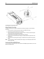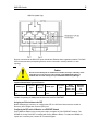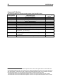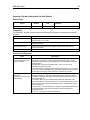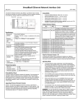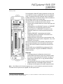
1
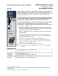
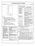
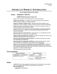
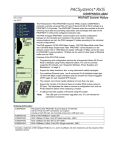
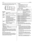
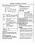
PACSystems* RX3i CEP IC695CEP001 RX3i CEP Carrier GFK-2884A February 2014 * The PACSystems RX3i CEP Carrier interfaces a remote node of one RX3i IO module to a PROFINET IO Local Area Network (LAN). The optional RX3i CEP Expansion Carrier, attached to the RX3i CEP Carrier, provides the ability to add one additional RX3i IC694 IO module to the remote node. The RX3i CEP Carrier works as a PROFINET IO-Device. The RX3i CEP Carrier’s main Remote IO functions include: Scanning all the modules within the remote node (input and output scan). Publishing data on the PROFINET network to a PROFINET IO-Controller at a user-specified production period. Receiving data from a PROFINET IO-Controller on the PROFINET network at a customer-specified production period. Managing PROFINET communication and module configuration between a PROFINET IO-Controller and modules within the remote node. Managing the state of the I/O when communications is lost Publishing fault information (alarms, diagnostics, etc.) to the PROFINET IO-Controller The insertion and removal of IO modules is the same as in an RX3i Universal Backplane. See PACSystems RX3i System Manual, GFK-2314 for details on insertion and removal of IO modules. The RX3i CEP Carrier (IC695CEP001) provides two RJ-45 Ethernet receptacles. It supports 10/100BASE-TX Ethernet standard interface. Features Note: Full programming and configuration services for all supported RX3i IO Modules using Proficy Machine Edition. For a list of currently supported IO modules, see page 12. Support daisy-chain/line, star, or ring (redundant media) network topologies. Two switched Ethernet ports: two eight-conductor RJ-45 shielded twisted pair 10/100 Mbps copper interfaces. A USB port for field updates of firmware using WinLoader. The USB port is for firmware upgrades only. It is not intended for permanent connection The CEP Carrier requires a user-supplied +24 VDC power source. * indicates a trademark of GE Intelligent Platforms, Inc. and/or its affiliates. All other trademarks are the property of their respective owners. All rights reserved. 2 RX3i CEP Carrier GFK-2884A Ordering Information IC695CEP001 RX3i CEP Carrier with RJ-45 Copper Ethernet Interface IC694CEE001 RX3i CEP Expansion Carrier Specifications PROFINET support PROFINET Version 2.3 Class A IO-Device RX3i Controller version required IC695CPU315/CPU320/CPE305/CPE310, with firmware version 7.75 or later IC69PNC001 PROFINET IO-controller with firmware version 1.23 or later RXi Controller version required RXi Controller with firmware version 7.80 or later Proficy Machine Edition version required Version 8.0 SIM 5 or later Power requirements IC695CEP001: 5.25W (0.22 A) at 24VDC with or without Expansion Carrier 1 (IC694CEE001) DC power supply input range: 19.2V – 30V Module dimensions 177.2 mm x 51 mm x 35 mm (6.98 inches x 2.01 inches x 1.38 inches) Operating temperature range 0 to 60℃ maximum surrounding air temperature Number of Ethernet port connectors IC695CEP001: Two RJ-45 10/100Base-TX receptacles IC694CEE001: None USB connector (for firmware upgrades) IC695CEP001: One Micro-B connector. USB 2.0 compliant running at Fullspeed (12 MHz) in device mode IC694CEE001: None PNS Status and Control bits 32 input status bits and 32 output control bits I/O data update on the PROFINET LAN Configurable: 1ms, 2ms, 4ms, 8ms, 16ms, 32ms, 64ms, 128ms, 256ms and 512ms Number of IP addresses One. Supports Classless Inter-Domain Routing (CIDR) Number of MAC addresses Three. One per external port and one internal. External MAC addresses are only used for specialized Ethernet protocols such as MRP or LLDP I/O station maximum limits Number of I/O Modules per station IC695CEP001: One IC695CEP001 with IC694CEE001: Two I/O data per station 1024 bytes total 512 bytes of input data 512 bytes of output data Configuration Configured using Proficy Machine Edition when used with a PACSystems RX3i PROFINET Controller module, as part of an RX3i High-Speed IO LAN system. rd V2.3 GSDML file available for import into 3 -Party tools. For product standards, general operating specifications, and installation requirements, refer to the PACSystems RX3i System Manual, GFK-2314. 1 Value does not include the power consumption of the installed IO modules. When calculating the total power requirements, you will need to add the power consumption of the IO modules according to the IO module datasheet. 3 RX3i CEP Carrier GFK-2884A Additional Information Manuals can be downloaded from the Support website, http://support.ge-ip.com. PACSystems RX3i CEP Manual, GFK-2883 PACSystems RX3i PROFINET Controller Manual, GFK-2571 PACSystems RX3i PROFINET Controller Command Line Interface Manual, GFK-2572 PACSystems CPU Reference Manual, GFK-2222 PACSystems RX3i System Manual, GFK-2314 PACSystems RXi Distributed IO Controller User Manual, GFK-2816 General Installation Requirements This product is intended for use with the RX3i system. Its components are considered open equipment (having live electrical parts that may be accessible to users) and must be installed in an ultimate enclosure that is manufactured to provide safety. As a minimum, the enclosure shall provide a degree of protection against solid objects up to 12mm (e.g. fingers). This equates to a NEMA/UL Type 1 enclosure or an IP20 rating (IEC60529) providing at least a pollution degree 2 environment. Installation in Hazardous Areas The following information is for products bearing the UL marking for Hazardous Areas or ATEX marking for explosive atmospheres: Class 1 Division 2 Groups ABCD This equipment is open-type device and is meant to be installed in an enclosure suitable for the environment that is only accessible with the use of a tool. Suitable for use in Class I, Division 2, Groups A, B, C and D Hazardous Locations, or nonhazardous locations only. WARNING - Explosion hazard - substitution of components may impair suitability for Class I, Division 2; ATEX ZONE 2 Device must be mounted in an enclosure certified in accordance with EN60079-15 for use in Class I, Zone 2, Group IIC and rated IP54. The enclosure shall only be able to be opened with the use of a tool. Provisions shall be made, external to the apparatus, to provide the transient protection device to be set at a level not exceeding 140% of the rated voltage at the input terminals of this apparatus. ATEX Marking Ex nA IIC T4 X 0C < Ta < 60C 4 RX3i CEP Carrier GFK-2884A Normal Operation of Individual LEDs Power LEDs The RX3i CEP Carrier has two Power LEDs, PWR1 and PWR2 that indicate whether the power is applied and good corresponding to the two power sources. Green, ON Power is applied at the minimum specified level OFF The power supply does not have power or has failed. OK LED The OK LED indicates whether the CEP Carrier is able to perform normal operation. Green, ON RX3i CEP is OK Amber, ON Either the RX3i CEP Carrier or IO module has a fault Amber, blink pattern Fatal error. Flashes once between error codes. Fast blinking CEP has no valid MAC addresses OFF CEP has an unrecoverable fault Connect LED The CONN LED indicates the status of PROFINET connections. Green, ON At least one PROFINET connection (AR) exists with an IO-Controller Amber, blink pattern Fatal error. Flashes once between error codes blinked on the OK LED Amber, blink in 1Hz No device name configured OFF No PROFINET connection (AR) exists Port LEDs The RX3i CEP has two Port LEDs, PRT1 and PRT2 that indicate link speed, link connection and link activity corresponding to the two external Ethernet ports. Note: Green, ON Link connected, 100 Mbps Green, blinking Port active, 100 Mbps Amber, ON Link connected, 10 Mbps Amber, blinking Port active, 10 Mbps Amber, blink pattern Fatal error. Flashes once between error codes blinked on the OK LED OFF The associated Ethernet port is not connected to an active link (can be disabled by configuration) Multiple LEDs can blink in patterns that indicate special conditions, such as a request for module identification. For additional information, refer to the PACSystems RX3i CEP Manual, GFK-2883. 5 RX3i CEP Carrier GFK-2884A Quick Start Carrier Installation Requirements The CEP Carrier and Expansion Carrier can be mounted on a DIN rail or a panel. Adequate installation space is required for: 1. Clearance for communications port cables. 2. Power wiring. 3. Operating the DIN latch. The RX3i CEP Carrier with an IO module attached requires an enclosure with minimum depth of 165mm. Rated thermal specifications are based on a clearance of 5.1 cm (2 inches) above and below the equipment and 2.54 cm (1 inch) to the left of the RX3i CEP Carrier. Installing an RX3i CEP Carrier on a DIN Rail The carrier mounts on a standard EN 50022, 35mm x 7.5mm DIN rail. Conductive (unpainted) finish is required for proper grounding. For best resistance to vibration, the DIN rail should be installed horizontally on a panel using screws spaced approximately 15cm (6inch) apart. 1. With a small flathead screwdriver, pull out the two DIN rail latches and stand the carrier on the DIN rail. 2. Push in the two DIN rail latches so that the latches hold the DIN rail. 6 RX3i CEP Carrier GFK-2884A Panel Mounting For applications requiring maximum or long term resistance to mechanical vibration and shock, the panel-mounting method is strongly recommended. A minimum panel thickness of 2.4mm (.093in) is required. Note 1: Tolerances on all dimensions are ±0.2mm (0.078 inch) non-cumulative. Note 2: Apply 1.1–1.4Nm (10–12 in/lbs) of torque to M3.5 (#6-32) steel screws threaded into tapped holes in the panel. 7 RX3i CEP Carrier GFK-2884A Grounding Warning All CEP Carriers in a system must be grounded to minimize electrical shock hazard. Failure to do so can result in severe personal injury. The RX3i CEP Carrier and Expansion Carrier each provide two grounding connection contacts: the grounding clips at the back of the carrier, which require DIN rail installation Note: the grounding screw hole at the left-bottom of the carrier. When the Carrier is mounted on a DIN rail, the grounding clips on the back of the Carrier do not provide an adequate ground connection. The Carrier’s metal back must also be grounded using a separate conductor. 2 Ground each Carrier to the panel or enclosure using a minimum AWG #12 (3.3 mm ) wire with ring terminals. Use an M3 screw, star lock washer and a flat washer to connect the wire at the Carrier’s grounding hole. Connect the other end of the ground wire to a tapped hole in the grounded mounting panel or enclosure, using a machine screw, star lock washer and flat washer. Alternately, if the panel has a ground stud, use a nut and star lock washer for each wire on the ground stud to ensure adequate grounding. Where connections are made to a painted panel, the paint should be removed so clean, bare metal is exposed at the connection point. Terminals and hardware used should be rated to work with the aluminum carrier material. Note: The star lock washer method is suitable for a shield ground, but not suitable for a safety ground. 8 RX3i CEP Carrier GFK-2884A Installing Modules on the Carrier The insertion and removal of IO modules is the same as in an RX3i Universal Backplane. For details, refer to the PACSystems RX3i System Manual, GFK-2314. Caution Do not install a Power Supply module on the CEP or CEE Carrier. Attempting to do so could damage the module and/or the Carrier. Unsupported Modules Caution If an unsupported module is inserted in the CEP or CEE Carrier, the module will not be recognized correctly and could cause damage to the Carrier or the module. When an unsupported IO module is inserted in either the RX3i CEP Carrier or RX3i CEP Expansion Carrier, no alarm is reported to indicate this. For the latest updated list of supported IO modules, refer to page 12. Some unsupported IO modules have the same Distinguishing Class (for example, IC694MDL740 has the same Distinguishing Class as IC694MDL742). 9 RX3i CEP Carrier GFK-2884A Connecting Power Supplies You will need: Note: Two power supplies are required if using redundant power supplies. One 24 VDC power supply which provides a low voltage/limited current (LVLC) power source. (Example: the combination of an isolated DC supply and a fuse, listed 30VDC minimum and 3A maximum, connected in series with the input.) A power cord with 28–16 AWG / 0.08–1.32mm2 wires Ferrules for 28–16 AWG wires (optional) A frame ground wire, 28–16 AWG An input power terminal block – provided (WAGO Part Number 713-1103.) A small screwdriver, 2.5×0.4 mm/0.098×.0157 in Note: For CE Mark purposes, input power lines to the CEP Carrier should be limited 30 meters or less. Note: Before inserting the wires into the power connector terminal block, use a small screwdriver to release the spring clamp on the terminal block. 1. Using the power cord, attach the power supply to the power terminal block as shown in the following figure. Recommended wire stripping length is 6–7mm (0.25 in). 2. If using redundant power supplies, connect the second power supply to the input power terminal block. 3. Insert the input power terminal block into the Input Power connector. Note: There are no user-serviceable fuses in the CEP Carrier. 10 RX3i CEP Carrier GFK-2884A Connecting Power to the RX3i CEP Carrier Adding a Redundant Power Supply To add a redundant power supply to a system that is already in operation, use the following procedure. 1. Remove power from the primary power supply to the RX3i CEP carrier 2. Remove the power terminal block from the carrier. 3. Without disturbing the primary power supply input lines, connect the redundant power supply input lines to the power terminal block. 4. Insert the power terminal block into the Input Power connector. 5. Apply power to the redundant power supply. The PWR2 LED on the RX3i CEP carrier should be on. 6. Apply power to the primary power supply. The PWR1 LED on the CEP Carrier should be on. Note: For the procedure to swap a redundant power supply, see the PACSystems RX3i CEP Manual, GFK-2883. Connecting the CEP to the PROFINET Network The two external RJ-45 Ethernet ports, which provide 10/100 Mbps copper interfaces, are on the bottom of the CEP Carrier. 11 RX3i CEP Carrier GFK-2884A Devices connected to the RX3i CEP ports should have Ethernet Auto-negotiation enabled. The RX3i CEP Carriers and other participating devices can be connected in a daisy-chain/line, or star topology. Caution Do not connect both ports on the Ethernet interface, directly or indirectly, to the same device so as to form a circular network unless Media Redundancy is enabled with one node actively set up as the Media Redundancy Manager. Supported Network Media Types and Distances Media Type 10/100BASETX Connector Type Waveleng th (nm) RJ45 - Core Size (μm) Media Type CAT5/CAT5e/ CAT6 - Modal Bandwidth (MHz – Km) - Maximum Distance (m) 100 (maximum) PROFINET IO over wired infrastructure must be 100Mbps full-duplex or faster. The hardware is capable of operating at 10Mbps but should not be used for PROFINET. Assigning an IO Device Name to the CEP Before attempting to connect to or configure the CEP, the IO Device Name must be set with a Discovery and Configuration Protocol (DCP) tool. Configuring the CEP and its IO Modules on a PROFINET Network Proficy Machine Edition is the primary tool used to configure an RX3i PROFINET network. The GSDML file for the RX3i CEP is included with Proficy Machine Edition. To obtain the GSDML for import into a 3rd-Party tool, contact GE Technical Support. 12 RX3i CEP Carrier GFK-2884A Supported IO Modules The following modules can be used with this release of the RX3i CEP Carrier: Catalog Number Module Description Distinguishing 2 Classes Discrete Input Modules IC694MDL250 IC694MDL646 IC695MDL664 120 VAC Isolated Input (16 Points) 24 VDC Input, Neg/Pos Logic, 1 mSec Filter (16 Points) Digital Input Module with Diagnostics – 16-Channel IC694MDL742 IC694MDL916 IC695MDL765 12/24 VDC Output, 1 Amp, Positive Logic (16 Points), Fused Relay Output, 4 Amp (16 Points) Digital Output Module with Diagnostics – 16-Channel IC695ALG616 IC695ALG626 Analog Input, Voltage/Current, Configurable, (16 Channels) 3 Analog Input with HART Communications, Voltage/Current, 3 Configurable, (16 Channels) , 4 IC695ALG728 Analog Output with HART Communications, Voltage/Current, 4 (8 Channels)3, Isolated Analog Output module, voltage/current, (8 Channels) 3 none 16 in none Discrete Output Modules 16 out none none Analog Input Modules none none Analog Output Modules IC695ALG808 2 none none The RX3i CEP Carrier and the RX3i CEP Expansion Carrier cannot distinguish between modules within the same Distinguishing Class type. This means that any module physically present that is in the same class as the one configured will not alert the user with a System Configuration Mismatch fault on the Controller Fault Table. See GFK-2222 Chapter 3 for CPU operation during System Configuration Mismatch faults. 3 The RX3i CEP Carrier and the RX3i CEP Expansion Carrier do not support Interrupts from this module. 4 The RX3i CEP Carrier and the RX3i CEP Expansion Carrier do not support all HART features in this module. 13 RX3i CEP Carrier GFK-2884A Important Product Information for this Release Release History Version Firmware Release Date IC695CEP001-AAAA 1.00 January 2014 Comments Initial release Compatibility The PROFINET Scanner modules require the following CPU firmware and programming software versions: Proficy Machine Edition Proficy Machine Edition 8.0 version or later RX3i CPU Version PACSystems RX3i CPU, IC695CPU315/CPU320/CPE305/CPE310, with firmware version 7.75 or later RX3i PNC Version PACSystems RX3i PROFINET IO-Controller, IC695PNC001, with firmware version 1.23 or later RXi Controller Version PACSystems RXi Distributed IO Controller, ICRXICTL000, with firmware version 7.80 or later RX3i IO Modules For a complete list, refer to “Supported IO Modules”, on page 12. Restrictions and Open Issues Issue Description Loss of AR connection when another PNC try to connect CEP001 If the RX3i CEP Carrier has established a PROFINET connection with one PNC, when another PNC connects to the same RX3i CEP Carrier, the old PROFINET connection will be terminated and the new PROFINET connection will be accepted. The RX3i CEP cannot work as shared device. It only can accept one PROFINET connection at a time. It is recommended to configure all IO controllers and IO devices in one network on the same LAN in PME. PME checks the LAN for duplicate device names to avoid configuring the same device names for IO devices in one LAN. CEP001 goes to fatal error after lots of Low/Low-Low/Underrange Alarm testing When an RX3i IO module generates many Diagnosis Appears and Diagnosis Disappears alarms in a short time, the RX3i CEP Carrier might go to a fatal error state. In this state, the Carrier sometimes blinks code 6:8 or sometimes fails with OK LED off. For example, when using an IC695ALG616 module with RX3i CEP, if the ALG616 is configured to report faults for Low Low under range diagnosis and these diagnostic alarms appear and disappear quickly, the RX3i CEP Carrier will go to fatal error. For these cases, it is recommended to configure a reasonable Deadband value to avoid generating a high volume of Diagnosis Appear and Diagnosis Disappears alarms. To recover, cycle power to the RX3i CEP Carrier. 14 RX3i CEP Carrier GFK-2884A Operational Notes Note Description No alarm report when inserted an unsupported IO module When an unsupported IO module is inserted in either the RX3i CEP Carrier or RX3i CEP Expansion Carrier, no alarm is reported to indicate this. For a list of supported IO modules , see page 12. Some unsupported IO modules have the same Distinguishing Class (for example, IC694MDL740 has the same Distinguishing Class as IC694MDL742). If an unsupported module is inserted in the CEP or CEE Carrier, the module will not be recognized correctly. Wait time is too long to enter download mode If power to the RX3i CEP Carrier lost during a firmware update, a delay of more than 50 seconds might be required before the RX3i CEP Carrier can enter the firmware update mode again. USB port drivers When connecting the USB cable to the RX3i CEP Carrier, you may receive a warning for installing a driver that has not passed Windows Logo testing. Each RX3i CEP Carrier is recognized as a separate Windows device with separate installation, as each has a unique serial number. This is normal operation for this release. Network parameters for IO-Devices If the network parameters (IP Address, subnet mask, and gateway IP) assigned by the DCP tool are different from the configuration in the IO-Controller and the IO-Controller is configured to assign IP settings to devices, when the IO Controller assigns its IP settings, the settings previously stored from the DCP tool are lost. On a reset, the IO-Device is set to factory default values (0.0.0.0/0.0.0.0/0.0.0.0) as prescribed by the PROFINET specification. No Extra Module Alarms The RX3i CEP Carrier and RX3i CEP Expansion Carrier ignore all extra equipment. No Extra I/O Module faults or Loss of I/O Module faults are generated for unconfigured modules. Diagnosis Disappears alarms may be out of sequence with Diagnosis Appears alarms For RX3i Intelligent Modules Diagnosis Disappears alarms are generated by cyclically polling diagnostic data which may be slower than Appears messages generated by interrupt. Example: When re-applying field power, new channel alarms such as Hi/Low alarms may occur before the Loss of Field Power alarm clears. Affected modules are: IC695MDL664 IC695MDL765/ALG616 IC695ALG626 IC695ALG728 IC695ALG808