1
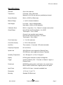
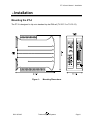
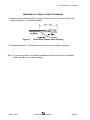
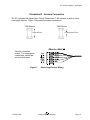
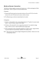
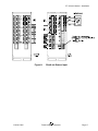
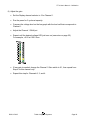
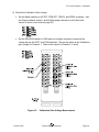
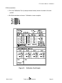
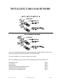
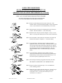
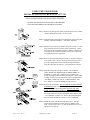
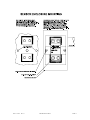
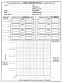
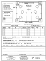
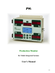
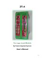
ZT-4 Tonnage Load Module By Toledo Integrated Systems User’s Manual 17618 ZT-4 Load Module User’s Manual Revision: A ZT-4 User’s Manual THIS PAGE INTENTIONALLY LEFT BLANK DOC #17495 Toledo Integrated Systems Page 2 ZT-4 User’s Manual Table of Contents Limited Warranty .............................................................................................................................. 4 Features Overview ........................................................................................................................... 5 Specifications ................................................................................................................................... 7 Installation ........................................................................................................................................ 9 Mounting the ZT-4 ........................................................................................................................ 9 DC Power Connection ................................................................................................................ 10 Shunt Resistors .......................................................................................................................... 11 Tonnage Gage Sensor Connection ............................................................................................ 12 20mA-out Sensor Connection..................................................................................................... 16 10V-out Sensor Connection........................................................................................................ 18 Analog Voltage Output................................................................................................................ 20 Analog Current Output ................................................................................................................ 21 Triggering – Internal Threshold................................................................................................... 22 Triggering – External Probe ........................................................................................................ 23 Calibration ...................................................................................................................................... 25 Front Panel Controls ................................................................................................................... 25 Notes – Bar-Graph Voltmeter ..................................................................................................... 25 Calibration Procedures ............................................................................................................... 26 Check Calibration ....................................................................................................................... 31 Operation ........................................................................................................................................ 33 Peak Mode Operation ................................................................................................................. 33 Track Mode Operation ................................................................................................................ 34 Appendix ......................................................................................................................................... 37 A) Sensor Installation (Doc# 11080) .................................................................................... 37 B) Calibration Sheets (2) (Form# 1224) ............................................................................... 37 Table of Figures Figure 1: Mounting Dimensions ..................................................................................................... 9 Figure 2: DC Power Wiring .......................................................................................................... 10 Figure 3: Channel 1 Built-In 1M Ohm Shunt Resistor Wiring ...................................................... 11 Figure 4: Channel 1 External Shunt Resistor Installation ............................................................ 11 Figure 5: Strain Gage Sensor Input ............................................................................................. 13 Figure 6: Strain Gage Sensor Cable Stripping ............................................................................ 14 Figure 7: Strain Gage Sensor Wiring ........................................................................................... 15 Figure 8: 20mA-out Sensor Input ................................................................................................. 17 Figure 9: 10V-out Sensor Input .................................................................................................... 19 Figure 10: Analog Voltage Output Wiring ................................................................................... 20 Figure 11: Analog Current Output Wiring ................................................................................... 21 Figure 12: Internal Threshold Wiring .......................................................................................... 22 Figure 13: Probe Input Wiring .................................................................................................... 23 Figure 14: Probe Timing Diagram .............................................................................................. 24 Figure 15: Calibration Gain Voltage Measurement .................................................................... 29 Figure 16: Calibration Card Sample ........................................................................................... 30 DOC #17495 Toledo Integrated Systems Page 3 ZT-4 User’s Manual Limited Warranty This unit is warranted by the manufacturer, Toledo Transducers, Inc., to be free of defects in workmanship and materials for one year from date of manufacturer’s shipment. This warranty is limited to repairing or replacing products which manufacturer’s investigation shows were defective at the time of shipment by the manufacturer. All products subject to this warranty must be returned for examination, repair or replacement F.O.B. to: Toledo Transducers, Inc. 6834 Spring Valley Drive Holland, Ohio 43528 The express warranty set forth herein is in lieu of all other warranties, expressed or implied, including without limitation any warranties of merchant-ability or fitness for a particular purpose. All such warranties are hereby disclaimed and excluded by the manufacturer. Repair or replacement of defective products as provided above is the sole and exclusive remedy provided thereunder. The manufacturer shall not be liable for any further loss, damages, or expenses, including incidental or consequential damages, directly or indirectly arising from the sale or use of this product. Any unauthorized repair voids this warranty. There are no warranties that extend beyond those expressly set forth herein. DOC #17495 Toledo Integrated Systems Page 4 ZT-4 User’s Manual Features Overview Designed to work with strain gage sensors and load cells. The ZT-4 can also accept input from 4-20mA current output sensors or voltage output sensors. Four independent channels for accommodating up to eight sensors. Simultaneously provides normal peak, reverse peak, and track voltage outputs. Channel 1 provides the associated 0-20mA current outputs. Built-in threshold trigger simplifies installation. External probe trigger can also be used when situation required. LED bar-graph voltmeter for easy setup and diagnostic. Built-in 1 Mega Ohm calibration shunt resistor. Channel 1 accepts user selected external shunt resistor. x1 and x10 amplifier gain ranges to work with either strong or weak signal from the load sensor. Auto-Zero can be selected using dip switches to compensate for zeroing errors caused by environmental changes such as temperature, humidity, and etc. Electrical noise rejection filter can be enabled when situation required. Plug-in connectors for easy wiring and installation. Standard DIN Rail mount simplifies systems integration. Modular with common bus design allows future upgrade and expansion. The ZT-4 tonnage load module is designed for critical force measurement applications where accuracy, extreme stability, and dependable noise rejection is essential. It is equipped with an LED bar-graph voltmeter for easy setup and diagnostic. The ZT-4 is DIN rail mountable and is designed to interface with a PLC analog card and to display output through a human machine interface (HMI). DOC #17495 Toledo Integrated Systems Page 5 ZT-4 User’s Manual THIS PAGE INTENTIONALLY LEFT BLANK DOC #17495 Toledo Integrated Systems Page 6 ZT-4 User’s Manual Specifications Channels One to four channels Transducers Full bridge, 120 to 1000 ohms. Maximum of (2) 350 ohm sensors, paralleled per channel. Sensor Excitation Built in +10VDC at 250mA max. Balance Range +/- 1mV/V of sensor imbalance Gain Ranges Low range = x50 to x550 adjustable High range = x500 to x5,500 adjustable Calibration Shunt Built-in 1 mega ohm (.1%). Channel 1 accepts custom shunt. Output Range Normal Peak and Reverse Peak = 0 to 10VDC Track output = -10 to +10VDC Channel 1 also provides current outputs: Normal Peak and Reverse Peak = 0 to 20mA Track output = -20 to +20mA Circuit Inaccuracy +/- .1% of full scale max. Circuit Non-linearity +/- .02% of full scale max. Auto Zero Time constant = 10 seconds. DIP switch selectable. Frequency Response DC to 5,000 Hz Speed Limit 2000 SPM max. when triggered by External Probe 500 SPM max. when triggered by Internal Threshold Operating Temperature -4 to 158 degree F, or -20 to 70 degree C Display LED bar-graph voltmeter for setup and diagnostic Trigger Internal Threshold (.35V / .70V) base on Channel 1 signal, or External Probe. Probe Input NPN/PNP proximity probes, solid state or dry contact relays. Built-in 24VDC at 80mA max. supplies power to the probe. Input Power 24VDC at 0.5A max. Automatic resettable fuse. Dimensions 1.9” W x 4.1” H x 4.7” D Mounting Standard DIN Rail mount DOC #17495 Toledo Integrated Systems Page 7 ZT-4 User’s Manual THIS PAGE INTENTIONALLY LEFT BLANK DOC #17495 Toledo Integrated Systems Page 8 ZT-4 User’s Manual – Installation Installation Mounting the ZT-4 The ZT-4 is designed to clip onto standard top hat DIN rail (TH 35-7.5 or TH 35-15). Figure 1: DOC #17495 Mounting Dimensions Toledo Integrated Systems Page 9 ZT-4 User’s Manual – Installation DC Power Connection 24VDC power is connected to the ZT-4 as shown in Figure 2. Figure 2: DC Power Wiring Notes: 1) The 24VDC source can be in range from 18VDC to 32VDC. 2) It is important to connect an Earth Ground to the GND terminal. 3) Do not apply power until all the wirings in this Installation Section are done. DOC #17495 Toledo Integrated Systems Page 10 ZT-4 User’s Manual – Installation Shunt Resistors Each channel comes with an 1M ohm built-in shunt resistor. Channel 1 is capable of utilizing either the 1M ohm built-in shunt resistor or a user-specified external shunt resistor. OR Figure 3: Channel 1 Built-In 1M Ohm Shunt Resistor Wiring Figure 4: Channel 1 External Shunt Resistor Installation Shunt resistor only works directly with the Wheatstone bridge type sensor. It has no effect if other type of sensor is used. DOC #17495 Toledo Integrated Systems Page 11 ZT-4 User’s Manual – Installation Strain Gage Sensor Connection Refer to Figure 5 for the procedures below: Connection: 1) Prepare the sensor cable for termination as described in Illustration A on page 14. 2) Remove the Phoenix plug from its socket on the top of the unit (CH1-3) or from the bottom of the unit (CH4) and wire the sensor cable as described in Illustration B on page 15. 3) The Phoenix plug can then be inserted back into its socket. Configuration: 1) Set the V / C dip-switch for the corresponding channel to “V” position for voltage sensor. Strain Gage sensor outputs voltage signal. 2) Set the Lg / Sm dip-switch for the corresponding channel to “Sm” position for small signal. Strain Gage sensor outputs un-amplified signal (small signal). 3) Set FIL dip-switch for the corresponding channel to “No filter” position. Apply this filter only when electrical noise becomes a problem at the analog output. Note: There are four sets of Sensor Signal Configuration dip-switches. Each set is for the corresponding channel. DOC #17495 Toledo Integrated Systems Page 12 ZT-4 User’s Manual – Installation Figure 5: DOC #17495 Strain Gage Sensor Input Toledo Integrated Systems Page 13 ZT-4 User’s Manual – Installation Illustration A - Sensor Cable Termination 1) Strip the sensor cable as shown in Figure 6 below. Be sure not to knick any of the signal conductors or cut the braid shield. Figure 6: Strain Gage Sensor Cable Stripping 2) Strip approximately ¼" of insulation from each of the four signal conductors. Note: If your sensor cable is not double shielded with both foil and a braid, electrical noise may affect your output readings. DOC #17495 Toledo Integrated Systems Page 14 ZT-4 User’s Manual – Installation Illustration B - Sensors Connection The ZT-4 accepts the signals from Toledo Transducers T-400 sensors as well as other strain gage sensors. Figure 7 illustrates the sensor connections. T400 Sensor T400 Sensor Tension Force Compression Force Tension connection shown. For compression connections, switch the red and white wires Figure 7: DOC #17495 Strain Gage Sensor Wiring Toledo Integrated Systems Page 15 ZT-4 User’s Manual – Installation 20mA-out Sensor Connection The 20mA-out Sensor applies to sensors with output up to +/-20mA including the 4-20mA output sensor. Refer to Figure 8 for the procedures below: Connection: 1) Remove the Phoenix plug from its socket on the top of the unit (CH1-3) or from the bottom of the unit (CH4) and wire the sensor cable as shown. 2) The Phoenix plug can then be inserted back into its socket. Configuration: 1) Set the V / C dip-switch for the corresponding channel to “C” position for current output sensor. 20mA-out sensor outputs current signal. 2) Set the Lg / Sm dip-switch for the corresponding channel to “Lg” position for large signal. 20mA-out sensor outputs amplified signal (large signal). 3) Set FIL dip-switch for the corresponding channel to “No filter” position. Apply this filter only when electrical noise becomes a problem at the analog output. Note: There are four sets of Sensor Signal Configuration dip-switches. Each set is for the corresponding channel. DOC #17495 Toledo Integrated Systems Page 16 ZT-4 User’s Manual – Installation Figure 8: DOC #17495 20mA-out Sensor Input Toledo Integrated Systems Page 17 ZT-4 User’s Manual – Installation 10V-out Sensor Connection The 10V-out Sensor applies to sensors with output up to +/-10V. Refer to Figure 9 for the procedures below: Connection: 1) Remove the Phoenix plug from its socket on the top of the unit (CH1-3) or from the bottom of the unit (CH4) and wire the sensor cable as shown. 2) The Phoenix plug can then be inserted back into its socket. Configuration: 1) Set the V / C dip-switch for the corresponding channel to “V” position for voltage sensor. 10V-out sensor outputs voltage signal. 2) Set the Lg / Sm dip-switch for the corresponding channel to “Lg” position for large signal. 10V-out sensor outputs amplified signal (large signal). 3) Set FIL dip-switch for the corresponding channel to “No filter” position. Apply this filter only when electrical noise becomes a problem at the analog output. Note: There are four sets of Sensor Signal Configuration dip-switches. Each set is for the corresponding channel. DOC #17495 Toledo Integrated Systems Page 18 ZT-4 User’s Manual – Installation Figure 9: DOC #17495 10V-out Sensor Input Toledo Integrated Systems Page 19 ZT-4 User’s Manual – Installation Analog Voltage Output The analog voltage output is provided on a Phoenix connector for easy access and for interfacing with other peripherals. Analog Voltage Output: Swing between ± 10VDC OUT0 = Normal Output (Average/Total Channel) OUT1-4 = Normal Output (Channel 1 to 4) REV1-4 = Reverse Output (Channel 1 to 4) TRK1-4 = Track Output (Channel 1 to 4) COM Figure 10: = Analog Common Analog Voltage Output Wiring Output details: OUT terminals output either Peak tonnage or Track tonnage, depending on the TRK/PEAK switch setting on the front panel. REV terminals output the reverse peak (snap-through) tonnage when the front panel TRK/PEAK switch is set to PEAK. TRK terminals always output the track tonnage, regardless of the front panel TRK/PEAK switch. DOC #17495 Toledo Integrated Systems Page 20 ZT-4 User’s Manual – Installation Analog Current Output The analog current output is available in Channel 1 only. It is provided on a Phoenix connector for easy access and for interfacing with other peripherals. Analog Current Output (Channel 1 only): Swing between ± 20mA OUT_C1 = Normal Output REV_C1 = Reverse Output TRK_C1 = Track Output COM Figure 11: = Analog Common Analog Current Output Wiring Output details: OUT_C1 terminal outputs either Peak tonnage or Track tonnage, depending on the TRK/PEAK switch setting on the front panel. REV_C1 terminal outputs the reverse peak (snap-through) tonnage when the front panel TRK/PEAK switch is set to PEAK. TRK_C1 terminal always outputs the track tonnage, regardless of the front panel TRK/PEAK switch. DOC #17495 Toledo Integrated Systems Page 21 ZT-4 User’s Manual – Installation Triggering – Internal Threshold The ZT-4 can be triggered by an internal threshold value. When this triggering method is used, the ZT-4 begins monitoring when the Channel 1 load rises above the level determined by the front panel’s Th.H / L switch. Refer to Figure 12 below to configure the unit for threshold triggering. Figure 12: Internal Threshold Wiring The probe (PRB) indicators should turn on when the Channel 1 load rises above the threshold value, and turn off when the load falls back below the threshold value. DOC #17495 Toledo Integrated Systems Page 22 ZT-4 User’s Manual – Installation Triggering – External Probe The ZT-4 can be triggered by an external probe signal. If an external probe is used, the probe supply voltage (+24VDC) is provided by the ZT-4. The figure below illustrates the wiring for a variety of sensing devices. Figure 13: Probe Input Wiring The probe (PRB) indicators should turn on when the probe turns on, and turn off when the probe turns off. DOC #17495 Toledo Integrated Systems Page 23 ZT-4 User’s Manual – Installation If the front panel Auto-Zero switch is enabled, the ZT-4 will remain in the auto-zeroing mode of operation until an external probe is applied. The auto zero feature is important for accurate readings. Over time the press frame will slightly change in its structure. This may be due to temperature or press frame tension. The ZT-4 will compensate for the slight change. It will readjust the zero base line. This zero base line is the no-load value of the press. With a consistent zero value, the tonnage output readings should remain accurate. When the probe turns on, the ZT-4 opens the window to read a load signal. In peak mode the load level rises to the highest value. When the probe turns off, the peak level is held at its high level and the auto-zeroing function is resumed (Notice the dotted line below). The peak level is reset the next time the probe transitions from off to on. The timing of the probe should be such that it turns on just before the machine begins generating a load (140) and remains on until the load is removed (240). Peak Reset Load Signal Probe Closed Trigger140° Probe 240° 140° 240° Probe Open ZT-4 Auto Zeroing Figure 14: DOC #17495 Probe Timing Diagram Toledo Integrated Systems Page 24 ZT-4 User’s Manual – Calibration Calibration Front Panel Controls Refer to the diagram below for control locations. Notes - Bar-Graph Voltmeter Normally, a digital voltmeter is used to check the sensor balance, and output voltage during a calibration. The digital voltmeter is connected to the OUTx and COM terminals (see Figure 15). If calibration accuracy of +/-1% of capacity is acceptable, the built-in Bar-graph voltmeter can be used for calibration. Let us use the +6.0 VOLT LED in the built-in Bar-graph voltmeter as an example here. When this LED is on, it could mean a voltage anywhere from +6.00 volt to +6.99 volt. But when this LED just changes state from off to on, it indicates an accurate reading of +6.00 volt. This characteristic is useful when you dial the gain pot to adjust the output voltage. This characteristic applies to all LED’s in this Bar-graph voltmeter. In case you need to set the output voltage to +5.50 volt, the Bar-graph voltmeter will not work accurately. You will need to use a digital voltmeter for cases like this. DOC #17495 Toledo Integrated Systems Page 25 ZT-4 User’s Manual – Calibration Calibration Procedures 1) Before calibrating the unit, verify each hardware mentioned in the Installation Section is connected and set up properly. 2) With the sensors placed in the best possible location, (see appendix A), torque the sensors down to 150 in-lbs on the sensor bolts. Do not put the sensor enclosure covers on yet. You will need to test each sensor location. 3) Find the shut height of the press. Jog the press until the ram is at bottom dead center (BDC) or 180º without the load cells or die in the press. Determine the amount of spacers needed with your load cell. Cycle the press without load cells to insure correct height. 4) Place the load cells in the correct position in the press. All load cells should be equal distance from the sides and front and rear. For example, 12” from the sides, 10” from front and rear. Load cells are typically placed at each corner of the press’s bed. Cycle the press without hitting the load cells first. Place cardboard on the top and bottom of the load cells. 5) Toggle the Mode switches to AZ OFF, PRB OFF, TRACK, ZERO. Also, set all Gain switches to X10 to start. DOC #17495 Toledo Integrated Systems Page 26 ZT-4 User’s Manual – Calibration 6) Balance the tonnage sensors. Set the Display channel selector to 1 for Channel 1. The Bar-graph voltmeter now shows the balance of Channel 1. Adjust the Channel 1 ZERO pot until the bar-graph has only the 2 yellow 0.0V LEDs lit. This indicates a balanced or zeroed state (see notes on page 25). Repeat this step for Channels 2, 3, and 4. 7) Cycle the press. Set the Mode switches to AZ OFF, PRB, PEAK, and ZERO. Further adjust the shut height so that the press impacts the load cells and generates a load at 100% of press capacity. See warning below. WARNING Depending on the press capacity and the size of the load cells being used, loading the press at capacity with load cells could indent the ram or bolster. If this is a concern, you may choose to calibrate the press only up to 80% of capacity. DOC #17495 Toledo Integrated Systems Page 27 ZT-4 User’s Manual – Calibration 8) Adjust the gain. Set the Display channel selector to 1 for Channel 1. Run the press for 2 cycles at capacity. Compare the voltage level on the bar-graph with the load cell that corresponds to Channel 1. Adjust the Channel 1 GAIN pot. Repeat until the desired voltage LED just turns on (see notes on page 25). For example, +6.0V at 100.0 tons. If less gain is needed, change the Channel 1 Gain switch to X1, then repeat from Step 4 for this channel only. Repeat this step for Channels 2, 3, and 4. DOC #17495 Toledo Integrated Systems Page 28 ZT-4 User’s Manual – Calibration 9) Record the Calibration Gain Voltage. Set the Mode switches to AZ OFF, PRB OFF, TRACK, and ZERO as shown. Use the Display channel selector, and the Bar-graph voltmeter to verify that each sensor is at zero (see notes on page 25). Set the ZRO/GAIN switch to GAIN and use a digital voltmeter to measure the voltage across the OUT1 and COM terminals. Record this value as the Calibration gain voltage for Channel 1. Then do the same for Channel 2, 3 and 4. Figure 15: DOC #17495 Calibration Gain Voltage Measurement Toledo Integrated Systems Page 29 ZT-4 User’s Manual – Calibration 10) Documentation. Fill in the Calibration Card (a sample shown below) which is located in the side pocket. Set Mode switches as shown. Calibration is now complete. Figure 16: DOC #17495 Calibration Card Sample Toledo Integrated Systems Page 30 ZT-4 User’s Manual – Calibration Check Calibration Occasionally, you may need to check the unit's accuracy by verifying the Calibration gain voltage. The Calibration gain voltage is recorded in the calibration card which is located in the side pocket. To verify the Calibration gain voltage, follow step 9 (page 29) in the Calibration Procedures. DOC #17495 Toledo Integrated Systems Page 31 ZT-4 User’s Manual – Calibration THIS PAGE INTENTIONALLY LEFT BLANK DOC #17495 Toledo Integrated Systems Page 32 ZT-4 User’s Manual – Operation Operation Once the ZT-4 has been calibrated, it is ready for continuous use. This section details the setup for Peak Mode and Track Mode operations. Peak Mode Operation In Peak mode, the output will increase to the highest load level and remain at that voltage until the probe transitions from off to on again. 1) Set the Mode switches to AZ OFF, PRB OFF, TRK, and ZRO as shown above. 2) Skip this step if Auto-Zero is not needed. a) Toggle the OFF/AZ switch to AZ to start Auto-Zero. b) When Auto-Zero is done, only the 2 yellow LEDs at 0.0V are lit. DOC #17495 Toledo Integrated Systems Page 33 ZT-4 User’s Manual – Operation 3) Set the OFF/PRB switch to PRB and set the TRK/PEAK switch to PEAK. The unit is now ready to run in Peak mode. Track Mode Operation In Track mode, output will follow the loading on the sensors as the load on the machine increases and decreases. 1) Set the Mode switches to AZ OFF, PRB OFF, TRK, and ZRO as shown above. If Auto-Zero is not needed, skip the following steps. The unit is now ready to run in Track mode. DOC #17495 Toledo Integrated Systems Page 34 ZT-4 User’s Manual – Operation 2) If Auto-Zero is needed, then a) Toggle the OFF/AZ switch to AZ to start Auto-Zero. b) When Auto-Zero is done, only the 2 yellow LEDs at 0.0V are lit. 3) Set the OFF/PRB switch to PRB. The unit is now ready to run in Track mode. DOC #17495 Toledo Integrated Systems Page 35 ZT-4 User’s Manual – Operation THIS PAGE INTENTIONALLY LEFT BLANK DOC #17495 Toledo Integrated Systems Page 36 ZT-4 User’s Manual – Appendix Appendix A) B) DOC #17495 Sensor Installation (Doc# 11080) Calibration Sheets (2) (Form# 1224) Toledo Integrated Systems Page 37 ZT-4 User’s Manual – Appendix THIS PAGE INTENTIONALLY LEFT BLANK DOC #17495 Toledo Integrated Systems Page 38 INSTALLING T400 LOAD SENSORS The above illustrations represent the proper arrangement of Model T400 Load Sensor kit parts using either the Drill and Tap method or the Weld method. A proper installation is necessary to produce good results. Before installing the sensors, please read the appropriate instructions listed below. Sensor Placement Press Frame Pitman Mount Drill and Tap Method of Installing Sensors Weld Method of Installing Sensors T400 Enclosure Mounting Details Doc #: 11080 Rev :A T400 INSTALLATION Page 2 Page 3 Page 4 Page 5 Page 6 Page 7 PAGE 1 Doc #: 11080 Rev :A T400 INSTALLATION PAGE 2 Doc #: 11080 Rev :A T400 INSTALLATION PAGE 3 Doc #: 11080 Rev :A T400 INSTALLATION PAGE 4 USING THE T400 SENSOR INSTALLATION FIXTURE KIT No. 1977-749 (METRIC INSTALLATION FIXTURE KIT No. 1974-749) DRILL AND TAP METHOD FOR MOUNTING SENSORS BE SURE THE SENSOR LOCATION FOLLOWS THE BEST LOCATION DESCRIBED ON THE PREVIOUS PAGES. STEP 1 Remove all paint and grease from sensor mount area. If the machine surface is flat (total indicated reading of .002”) and smooth (125 µ in.) the load sensor can be bolted directly to the surface. STEP 2 Drill and tap the center hole for mounting the fixture to the press member. This hole should be ½ inch (13mm) deep. STEP 3 Bolt the fixture to the press member using the ¼-28 by 1-¼ inch (M6-1 x 35) long socket head cap screw in the center of the fixture. STEP 4 Insert the number 3 drill (5mm) into the smaller corner hole and drill out all four holes to a depth of ¾ of an inch (19mm.) STEP 5 Loosen the fixture. Rotate the fixture 90 degrees clockwise. Tighten the center screw of the fixture. Insert the number 21 drill into the small centered hole and drill out both holes to a depth of 3/8 of an inch. These holes are for mounting the sensor enclosure. The fixture does not allow for tapping these holes. They are tapped without the fixture. Enclosure mounting is not done in metric. STEP 6 Loosen the fixture. Rotate the fixture another 90 degrees clockwise such that the larger corner holes line up with the holes drilled in Step 4. Insert a tap to be sure the holes line up. Lock the fixture in place by tightening the center screw. STEP 7 Insert the tap into the larger tap guide holes and tap each hole. BE SURE TO USE PLENTY OF TAPPING FLUID. STEP 8 Remove the fixture and repeat Steps 1-7 for each additional sensor mounting position. STEP 9 Mount the sensor with the raised rib to the press. The anti-torque washers should go between the screw and the sensor body. Torque each ¼-28 x ¾ in. long socket head cap screw to 150 LB.-IN or 12.5 LB.-FT. Doc #: 11080 Rev :A T400 INSTALLATION PAGE 5 USING THE T400 SENSOR INSTALLATION FIXTURE KIT No. 1977-749 WELD PAD METHOD FOR MOUNTING SENSORS BE SURE THE SENSOR LOCATION FOLLOWS THE BEST LOCATION DESCRIBED ON THE PREVIOUS PAGES. STEP 1 Remove all paint, grease, and or rust from surface to be welded. (Surface should be flat T.I.R. 1/32 of an inch.) STEP 2 Drill and tap the center hole for mounting the fixture to the press member. This hole should be ½ inch deep. (Optional) STEP 3 Bolt the fixture to the press member using the ¼-28 by 1-¼ inch long socket head cap screw in the center of the fixture. Orient the fixture as shown and drill out the #21 holes to a depth of 3/8 of an inch for the enclosure mounting. The fixture is not used for tapping these holes. (Optional) STEP 4 Remove the fixture from the press member. Bolt the weld pads to the fixture with ¼-28 by 1 inch long socket head cap screws provided. Reattach the fixture with the weld pads bolted on using the center hole as in Step 3. Orient the fixture as shown. STEP 5 Weld the weld pads to the press member. (BE SURE TO ONLY WELD THE WELD PADS ON THREE SIDES AS SHOWN.) A single pass is sufficient. Do not remove the fixture until slag is removed and or assembly has cooled. When welding cast iron, use a dry nickel rod such as: Lincoln Electric “Soft Weld”, Hobart “NI Cast 99”, or MB Weld Prod. “MG 210. Strike arc on steel then puddle into the cast iron. STEP 6 Remove the weld fixture. DO NOT WELD AFTER FIXTURE IS REMOVED. The 4 screws holding the pads to the fixture and the 1 center screw may be discarded. DO NOT USE THE FOUR 1 INCH LONG SCREWS TO ASSEMBLE SENSOR. The sensor kit contains four ¾ inch long screws for assembling the sensor to the press member. Weld pad surface must be clean – no weld bumps, scratches, etc. Be sure the weld pad tapped holes are clean and bottom of holes are free of weld flash. STEP 7 Mount the sensor with the raised rib to the press. The antitorque washers should go between the screw and the sensor body. Torque each ¼-28 x ¾ in. long socket head screw to 150 LB.-IN or 12.5 LB.-FT. Doc #: 11080 Rev :A T400 INSTALLATION PAGE 6 Doc #: 11080 Rev :A T400 INSTALLATION PAGE 7