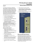
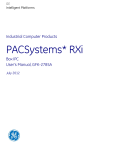
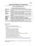
1
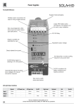
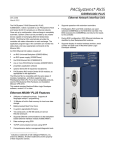
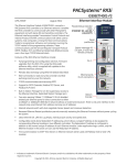
GE Intelligent Platforms Programmable Control Products PACSystems* RX3i Central Processing Unit IC695CPE305 Quick Start Guide GFK-2934A August 2015 Contents 1. User Features ..................................................................................................................... 1 1.1. 1.2. 1.3. 1.4. 1.5. 1.6. 1.7. 2. Switches ............................................................................................................... 3 Real-Time Clock Battery ....................................................................................... 4 Ethernet Port......................................................................................................... 4 Serial Port ............................................................................................................. 5 Removable Data Storage Devices (RDSDs) ......................................................... 5 Energy Pack ......................................................................................................... 5 Light-Emitting Diode Indicators (LEDs).................................................................. 6 Hardware Installation....................................................................................................... 8 2.1. 2.2. 2.3. Initial Checks ........................................................................................................ 8 Installation Location .............................................................................................. 8 Installation in Hazardous Areas ............................................................................. 9 3. Module Initial Startup ..................................................................................................... 11 4. Additional Information ................................................................................................... 13 i PACSystems* RX3i Central Processing Unit IC695CPE305Quick Start Guide GFK-2934A 1. User Features The PACSystems* RX3i CPE305 can be used to perform real time control of machines, processes, and material handling systems. The CPU communicates with the programmer via the internal Ethernet port or a serial port. It communicates with I/O and Intelligent Option modules over a dual PCI/Serial backplane. Contains 5 Mbytes of user memory and 5 Mbytes of nonvolatile flash user memory. Battery-less retention of user memory. Energy Pack IC695ACC400 on system power loss powers CPU long enough to write user memory to non-volatile storage (NVS). Configurable data and program memory. Programming in Ladder Diagram, Structured Text, Function Block Diagram, and C. Supports auto-located Symbolic Variables that can use any amount of user memory. Reference table sizes include 32Kbits for discrete %I and %Q and up to 32Kwords each for analog %AI and %AQ. GFK-2934A August 2015 1 Supports most Series 90-30 modules and expansion racks. For supported I/O, Communications, Motion, and Intelligent modules, refer to the PACSystems RX3i Hardware and Installation Manual, GFK-2314. Supports up to 512 program blocks. Maximum size for a block is 128KB. An RS-232 serial port. Embedded Ethernet interface supports up to 32 simultaneous SRTP Server connections, up to 16 simultaneous Modbus/TCP Server connections, and up to 16 simultaneous communications channels of either SRTP Channels or Modbus/TCP Client channels. For details, refer to the PACSystems RX7i & RX3i TCP/IP Ethernet Communications User Manual, GFK-2224. Effective with firmware version 8.20, this product supports OPC-UA. Effective with firmware version 8.30, this product supports Ethernet Global Data, Class 1. Effective with firmware version 8.50, this product supports HART® Pass Through. Time synchronization to SNTP Time Server on Ethernet network when used with a rack-based Ethernet module (IC695ETM001) version 5.0 or later. Ability to display serial number and date code in programmer Device Information Details. Ability to transfer applications to and from USB 2.0 A type removable data storage devices, or RDSDs. Compliant with EU RoHS Directive 2002/95/EC using the following exemptions identified in the Annex: 7(a), 7(c)-I and III, and 15. ® 2 HART® is a registered trademark of the HART Communication Foundation of Austin, Texas USA. Any use of the term HART hereafter in this document, or any document referenced by this document, implies the registered trademark. PACSystems* RX3i Central Processing Unit IC695CPE305Quick Start Guide GFK-2934A 1.1. Switches The RDSD and Run Mode switches are located behind the front protective door. The Reset switch is not used. Switch operation is given in the following table. Switch Operation RDSD Switches Function Start pushbutton Pressing this switch initiates RDSD data transfer. (The three-position switch must be set to Upload or Download.) Three-position switch Enables/disables RDSD data transfer and selects the direction of data transfer. Upload Loads application from CPU to RDSD. Off Disables RDSD data transfer. Download Stores application from RDSD to CPU. Run Mode Switch Switch Position A three-position switch which operates as follows: CPU and Sweep Mode Memory Protection The CPU runs with I/O sweep User program memory is enabled. read only. The CPU runs with outputs User program memory is Run Output Disable disabled. read only. The CPU is not allowed to go User program memory Stop into Run mode. can be written. The Run Mode switch can be disabled in the programming software in Hardware Configuration (HWC). The switch’s memory protection function can be disabled separately in HWC. The Run Mode switch is enabled by default. The memory protection functionality is disabled by default. Run I/O Enable GFK-2934A August 2015 3 1.2. Real-Time Clock Battery The CPE305 is shipped with a real time clock (RTC) battery (IC690ACC001) installed, with a pull-tab on the battery. The pull tab should be removed before installing the CPE305. There are no diagnostics or indicators to monitor RTC battery status. The RTC battery has an estimated life of 5 years and must be replaced every 5 years on a regular maintenance schedule. If the RTC battery fails, the CPU date and time is reset to 12:00 AM, 01-102000 at startup. The CPU operates normally with a failed or missing RTC battery; only the initial CPU Timeof-day (TOD) clock information will be incorrect. 1.3. Ethernet Port The embedded Ethernet interface supports communications with the Machine Edition programming software using the proprietary SRTP protocol. The CPE305 CPU provides two SRTP-server connections. The embedded Ethernet interface has one RJ-45 Ethernet port that automatically senses the data rate (10Mbps or 100Mbps), duplex status (half or full duplex), and cabling arrangement (straight through or crossover) of the attached link. 4 PACSystems* RX3i Central Processing Unit IC695CPE305Quick Start Guide GFK-2934A 1.4. Serial Port The CPE305 provides one RS-232 serial interface to external devices. This port can be used for firmware upgrades. The port is electrically isolated. For serial port pin assignments and details on serial communications, refer to the PACSystems RX3i and RX7i CPU Reference Manual, GFK-2222. The RS-232 port does not supply the 5VDC power offered by other RX3i and Series 90-30 CPUs. Cable IC693CBL316 must be used for RS-232 serial connections to the CPE305. 1.5. Removable Data Storage Devices (RDSDs) The CPE305 provides the ability to transfer applications to and from an RDSD (USB compatible device, such as a memory stick, smart phone, digital camera or MP3 device). Once the data is copied to the RDSD, it can be written to other RX3i CPE305 CPUs with no programmer software needed. The RDSD interface requires a usersupplied flash memory device that complies with the USB 2.0 Specification. The USB port must be enabled in the RX3i configuration in order to transfer data between the CPU and the RDSD. The CPE305 is shipped with the RDSD (USB) port enabled. Complete details of the use of RDSDs are found in the PACSystems RX3i and RX7i CPU Reference Manual, GFK-2222. 1.6. Energy Pack The CPE305 preserves user memory using an Energy Pack without the need to periodically replace batteries. The IC695ACC400 Energy Pack powers the CPU long enough for the CPU to write its user memory contents to the CPU’s non-volatile storage during a system power loss. Installation of the Energy Pack is found below. GFK-2934A August 2015 5 1.7. Light-Emitting Diode Indicators (LEDs) OK — indicates module readiness to perform normal operations. Green, ON steady OFF Green, blinking CPU passed power-up diagnostics , functioning properly Power is not applied or CPU has a problem, which may be indicated by RN and EN blink pattern CPU in Stop-Halt state; possible watchdog timer fault. Refer to the fault tables. If the programmer cannot connect, cycle power with a charged Energy Pack attached and refer to fault tables RN — indicates the run state of the CPU. Green, ON steady CPU is in Run mode. OFF CPU is in Stop mode. Green, blinking in unison with OK CPU is in boot mode and is waiting for a firmware update through a serial port. EN — indicates outputs enabled. Green, ON steady Output scan is enabled. OFF Output scan is disabled. CM — indicates activity on the serial communications port. Green, blinking Signal activity on the COM1 port. OFF No activity on COM1 port. IO FORCE — indicates override on a bit reference. 6 Amber, ON steady Override active on at least one bit reference. OFF No overrides applied. PACSystems* RX3i Central Processing Unit IC695CPE305Quick Start Guide GFK-2934A STATUS — indicates Energy Pack status. OFF Energy Pack not connected. Green, blinking Energy Pack charging; not yet charged above the minimum operating voltage. Red, ON Energy Pack circuit fault. Red, blinking Green, ON steady Energy Pack near its end of life and should be replaced soon. Energy Pack is charged above its minimum operating voltage. SYS FLT — indicates presence of a fatal fault. OFF No fatal faults. Red, ON CPU is in Stop/Faulted mode because a fatal fault has occurred. RDSD — indicates signal activity on the RDSD/COM2/USB port. GFK-2934A Green, blinking COM2 port activity OFF No COM2 port activity August 2015 7 2. Hardware Installation 2.1. Initial Checks Upon receiving your RX3i equipment, carefully inspect all shipping containers for damage. If any part of the system is damaged, notify the carrier immediately. The damaged shipping container should be saved as evidence for inspection by the carrier. As the consignee, it is your responsibility to register a claim with the carrier for damage incurred during shipment. GE Intelligent Platforms will fully cooperate with you, however, should such action be necessary. After unpacking the RX3i equipment, record all serial numbers. Serial numbers are required if you should need to contact Customer Care during the warranty period. All shipping containers and all packing material should be saved should it be necessary to transport or ship any part of the system. Verify that all components of the system have been received and that they agree with your order. If the system received does not agree with your order, contact Customer Care. 2.2. Installation Location This product is intended for use with the RX3i system. Its components are considered open equipment (having live electrical parts that may be accessible to users) and must be installed in an ultimate enclosure that is manufactured to provide safety. As a minimum, the enclosure shall provide a degree of protection against solid objects as small as 12mm (e.g. fingers). This equates to a NEMA/UL Type 1 enclosure or an IEC60529 IP20 rating providing at least a pollution degree 2 environment. For details about installing RX3i rack systems, refer to the PACSystems RX3i System Manual, GFK-2314. If you need technical help, contact Technical Support. For phone numbers and email addresses, see the back cover of this Guide. 8 PACSystems* RX3i Central Processing Unit IC695CPE305Quick Start Guide GFK-2934A 2.3. Installation in Hazardous Areas The following information is for products bearing the UL marking for Hazardous Areas or ATEX marking for explosive atmospheres: CLASS 1 DIVISION 2 GROUPS ABCD This equipment is an open-type device and is meant to be installed in an enclosure suitable for the environment that is only accessible with the use of a tool. Suitable for use in Class I, Division 2, Groups A, B, C and D Hazardous Locations, or nonhazardous locations only. Warning – EXPLOSION HAZARD - SUBSTITUTION OF COMPONENTS MAY IMPAIR SUITABILITY FOR CLASS I, DIVISION 2. Warning – WHEN IN HAZARDOUS LOCATIONS, TURN OFF POWER BEFORE REPLACING OR WIRING MODULES; AND Warning – DO NOT CONNECT OR DISCONNECT EQUIPMENT UNLESS POWER HAS BEEN SWITCHED OFF OR THE AREA IS KNOWN TO BE NONHAZARDOUS. Warning – EXPLOSION HAZARD - USB PORT IS ONLY FOR USE IN NONHAZARDOUS LOCATIONS, DO NOT USE UNLESS AREA IS KNOWN TO BE NON-HAZARDOUS. ATEX Zone 2 This product must be mounted in an enclosure certified in accordance with EN6007915 for use in Zone 2, Group IIC and rated IP54. The enclosure shall only be able to be opened with the use of a tool. 2.4. Module Installation For initial startup and configuration of the CPE305, complete the following steps. For full details on CPE305 operation, refer to the PACSystems RX3i and RX7i CPU Reference Manual, GFK-2222. 1. Remove the pull-tab from the Real Time Clock (RTC) battery, located on the back of the CPE305. GFK-2934A August 2015 9 2. Remove power from the RX3i rack and install the CPE305. The CPE305 may be installed in any slot in the RX3i Main rack, except the highest-numbered slot or slot 0. 3. Holding the module firmly, align the module with the correct slot and connector, then swing the module down until the module’s connector engages the backplane’s backplane connector. Visually inspect the module to be sure it is properly seated. 4. Insert the two provided M3x5mm machine screws through the module’s bottom bracket into threaded holes in the bottom of the backplate and screw them several turns using a #1 Phillips screwdriver. Tighten to 0.7 N-m (6 in-lbs). 5. Mount the Energy Pack on the left side of the module in slot 0 of the rack (typically a power supply). a. Engage the Energy Pack’s mounting hooks (at the top) on the frame of the leftmost module. b. Rotate the bottom of the Energy Pack into place, engaging the bottom hooks. The latch will snap into place. c. Connect cable IC695CBL001 from the connector on the bottom of the Energy Pack to … d. the corresponding connector on the bottom of CPE305. 6. If required, connect the CPE305 to the Ethernet network. 7. Apply power to the rack. 10 PACSystems* RX3i Central Processing Unit IC695CPE305Quick Start Guide GFK-2934A Note: When the Energy Pack is powered up for the first time, or is in a system that has been powered down long enough to completely discharge the Energy Pack, it may require a few seconds for it to charge to its operating level. The CPU’s STATUS LED will blink green during this time. 3. Module Initial Startup You Will Need: PACSystems RX3i CPU Firmware 8.00 or later. Proficy* Machine Edition configuration and programming software, version 8.0 or later. A IC693CBL316 serial or Ethernet cable for connecting the computer running the Proficy Machine Edition programmer to the RX3i CPU. Initial Configuration 1. Using Proficy Machine Edition (PME) software, configure the CPE305 in an RX3i target. Note: If you intend to use the module’s embedded Ethernet interface, you will probably need to assign it a new IP address. To configure the embedded Ethernet interface in Machine Edition, expand the CPU slot to display the Ethernet daughterboard. The Settings tab for the embedded Ethernet module contains IP Address, Subnet Mask and Gateway IP Address (see the following diagram). Consult your network administrator for the proper values for these parameters. GFK-2934A August 2015 11 Configuration of the Ethernet Port on CPE305 2. Go online with the target and download the configuration. You can use one of the following methods for the initial connection to the CPE305: a. Using an IC693CBL316 cable, connect to the module’s RJ-25 RS-232 serial port to the programmer computer. The computer must be equipped with an RS-232 serial port with a standard AT-style nine-pin male D-connector. b. Connect to the module’s Ethernet port, using the factory-loaded IP address, 192.168.0.100. Note: This address is intended only for initial connection in order to complete the configuration. After the initial configuration download, must be changed before connecting to the Ethernet network. When you store a hardware configuration with a different IP address, the temporary IP address is lost; it is not restored by a Clear operation. c. 12 Through the Ethernet connection of an ETM001 in the same rack with a known IP address configuration. PACSystems* RX3i Central Processing Unit IC695CPE305Quick Start Guide GFK-2934A 4. Additional Information PACSystems RX3i and RX7i CPU Reference Manual GFK-2222 PACSystems RX3i and RX7i CPU Programmer’s Reference Manual GFK-2950 PACSystems RX3i System Manual GFK-2314 PACSystems RX3i IC695CPE305 CPU Important Product Information GFK-2714 User manuals, product updates and other information sources are available on the Support website, http://www.ge-ip.com/support, under Controllers and IO, RX3i Controllers. GFK-2934A August 2015 13 GE Intelligent Platforms Contact Information Americas: 1-800-433-2682 or 1-434-978-5100 g Global regional phone numbers are available on our web site www.ge-ip.com Copyright © 2014-2015 General Electric Company. All Rights Reserved. * Trademark of General Electric Company and/or its subsidiaries. All other trademarks are property of their respective holders GFK-2934A