1
THEATRE Concept
ASSEMBLY AND CALIBRATION
www.cineversum.com
Date: 24092007
Rev: 04
Part. No.: R599752
Did you know that ?
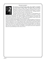
The process of anamorphosizing optics was originally developed
by French professor Henri Chrétien during World War I to provide a
wide angle viewer for military tanks. The optical process was called
Hypergonar by Chrétien and was capable of showing a field of view of
180 degrees. After the war, the technology was first used in a cinematic
context in the short film “Pour Construire un Feu” (To Build a Fire) in
1927 by French movie director Claude Autant-Lara.
Anamorphic wide screen was not used again for cinematography until
Henri Chrétien
Twentieth Century-Fox bought the rights to the technique in 1952 to
create their CinemaScope wide screen technique. CinemaScope was one of many wide
screen formats developed in the 1950s to compete with the popularity of television and
bring audiences back to the cinemas. The Robe, which premiered in 1953, was the first
feature film released that was filmed with an anamorphic lens.
lthough CinemaScope was capable of producing a 2.66:1 image, the addition of multichannel
sound reduced this to 2.55:1. Theater owners, however, were dissatisfied with contractually
having to install three or four-track magnetic stereo, and because of the technical nature
of sound installations, drive-in theaters had trouble presenting stereophonic sound at all.
Due to these conflicts, Fox revoked their policy of stereo-only presentations, and added an
optical sound track, while keeping the magnetic for those theaters that chose to present
their films with stereophonic sound. The addition of the optical sound track reduced the
width of the presented aspect ratio further to 2.35:1.
page 2
Table of content
Did you know that ? .................................................................................................... 2
Assembly Instructions: ............................................................................................... 4
Technical data:............................................................................................................. 4
Notes on safety:........................................................................................................... 4
Before assembly: ........................................................................................................ 4
The THEATRE concept: .............................................................................................. 5
Projection Distances and setting up the Anamorphic system: .............................. 5
Useful test patterns: ............................................................................................. 5
Projection Distances: ........................................................................................... 5
Remote Control Unit: .................................................................................................. 6
Description:.................................................................................................................. 6
State diagram using the RCU: .................................................................................... 6
RF-emitter for 12 V Trigger: ........................................................................................ 7
State Diagram using the 12 V Trigger: ...................................................................... 7
IMPORTANT:................................................................................................................. 7
Mounting the Anamorphic Lens (fig. A-B) ................................................................ 8
Mounting the THEATRE System to the Projector (fig. C) ....................................... 9
Adjustments in 16:9 position, without Anamorphic Lens (fig. D-F) ....................... 9
Scaler settings: ................................................................................................... 11
Switch from 16:9 to 2.35:1 (fig. G-H) ....................................................................... 11
Horizontal alignment in 2.35:1 position, with Anamorphic Lens (fig. I-K) ........... 12
Setting vertical position and tilt (fig. L-M) ............................................................... 14
Focus adjustment (fig. N-O) ..................................................................................... 15
Scaler settings and 12V Trigger configuration: ...................................................... 16
Recommended settings: .................................................................................... 16
Watching 16:9 and 2.35:1 movies on the same input ...................................... 16
Quick access buttons on the Remote Control Unit ......................................... 16
Watching a Cinemascope® movie with subtitles: .................................................. 17
2.40:1 movie on a 2.35:1 Cinemascope® screen: .................................................. 18
Scaler settings: ................................................................................................... 18
page 3
Assembly Instructions:
This product is designed to be used in private homes.
Correct assembly is essential for the long life and functionality of your THEATRE system.
Please observe the following points carefully.
Technical data:
-WxDxH: 424mm x 470mm x 124mm.
-Maximum load: 40 Kg in ceiling position.
-Net weight: 6.2 Kg (excluding lens)
-Adjustable 12° up and down.
-Auto-secured hook system.
Notes on safety:
-The mount is intended for fixing to the ceiling or table mounting.
-Before attaching the base to the mount check it thoroughly for any damage.
-Never use defective parts.
Before assembly:
-It is expressly recommended to have installation carried out by a specialist.
-Make sure that the quality of the ceiling is sufficient to hold the weight of the projector
plus that of the mount. If there is any doubt regarding the condition and load of the ceiling,
please consult a specialist from building trade.
-The fixing materials must be suitable for the type of wall so that the maximum load can be
guaranteed. For this reason no fixing materials have been included with the ceiling mount.
Please check a specialist, giving the relevant details.
-Also make sure that there are no electricity cables or gas/water pipes in the ceiling.
-Before assembling, check the location of the nearest main socket.
NB: CineVERSUM accepts no liability for damages caused by incorrect assembly or
by improper use.
page 4
The THEATRE concept:
The Theatre system is the ultimate all-in-one solution to watch Cinemascope® movies on
a real 2.35:1 screen.
Featuring a motorized slider for the Anamorphic Lens, the Theatre system is a versatile
solution to operate a 16:9 native resolution projector to display on demand, a Cinemascope®
movie with no more black bars, nor loss of brightness and at the full resolution of the
projector.
The Anamorphic System is used to move the THEATRE Anamorphic Lens in front of the
projector optical lens to transform the projected picture format from 16:9 to 2.35:1 aspect
ratio.
The Theatre system can be remotely controlled via radio-frequency, RS-232 or Infrared
remote control*.
HDTV program
Cinemascope® movie
Projection Distances and setting up the Anamorphic system:
The projected picture is enlarged horizontally during the process by a factor of 1.33x. For
this reason, the projection distance would be reduced by a factor of 1.33x when projecting
on a 2.35:1 format screen (wider format) instead of a 16:9 screen.
If you plan to watch both 16:9 and Cinemascope® contents, we recommend to use a
2.35:1 format screen with lateral masking such as curtains to obtain the greatest viewing
impact.
The Theatre system requires a calibration to perfectly match your system within the offset
and shift setting used with your projection screen. The scaler possesses test patterns that
can be used to calibrate the system in both 16:9 and Cinemascope® formats.
Useful test patterns:
Menu -> Configuration -> Test Patterns -> Frame Geometry, Xhatch Coarse, Xhatch Fine,
Focus.
Projection Distances:
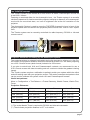
Diagonal (2.35:1)
Width
minimum Distance
maximum Distance
107” (272 cm)
99” (250 cm)
157” (400 cm) (**)
204” (519 cm)
128” (325 cm)
118” (300 cm)
157” (400 cm) (**)
244” (620 cm)
149” (378 cm)
137” (349 cm)
165” (420 cm)
284” (722 cm)
170” (431 cm)
157” (398 cm)
188” (479 cm)
324” (824 cm)
(*) The scaler Master Three is required for RS-232 and infrared commands.
(**) The minimum projection distance is 157” or 4 meters.
page 5
Remote Control Unit:
The THEATRE system uses Radio-Frequency signals to operate, make sure that it complies
with local recommendations before installing:
-Receiver frequency
433.92 Mhz
-Intermediate frequency
+/- 70 KHz
-Bandwidth
+/- 300 KHz
-Modulation type
AM/ASK
Description:
1
3
2
4
The RCU has 2 pairs of buttons:
-Button 1 (normal position) and Button 2 (Cinemascope®)
-Buttons 3 and 4 (optional control)
The THEATRE system is already programmed to operate with
buttons 1 and 2. The optional buttons 3 and 4 can be used to
control an external system such as standard RF Motorized screen
or screen masking.
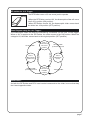
State diagram using the RCU:
The Anamorphic slider is controlled by button 1 and 2 of the RCU. The µ-switchs are
electronic devices that control the start and stop of the slider movements, OFF position
and ON position respectively.
�������
�������������
�����������
��������
�������������������
page 6
�������������������
��������
�������
������������
�������������
��������
��������
�������
�������������
��������
��������
�������
�����������
��������
��������
RF-emitter for 12 V Trigger:
The RF-Emitter uses a 3,5 mm mono jack to operate.
-When the RF-Emitter receive 12V, the Anamorphic slider will move
into 2.35:1 position (ON position).
-When RF-Emitter receive 0V, the Anamorphic slider moves back
the slider into 16:9 position (OFF position).
State Diagram using the 12 V Trigger:
The Anamorphic slider can also be controlled by a standard 3,5 mm jack 12-Volt trigger.
When a 12V is applied to the RF-Emitter, the slider moves to the ON position. When the
voltage is 0V, the slider moves back to the original position (OFF position).
�������
�������������
�����������
��������
���������������
�������������������
��������������
�������������������
���������������
�������
������������
�������������
��������������
��������������
�������
�������������
��������
��������
�������
�����������
��������
���������������
IMPORTANT:
As both the RF-Emitter and RCU send control commands to the slider, be sure that they
don’t send opposite orders.
page 7
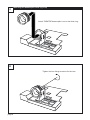
A
Mounting the Anamorphic Lens (fig. A-B)
Attach THEATRE Anamorphic Lens to the slider ring.
B
Tighten the four fixing screws to fix the lens.
page 8
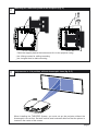
C
Mounting the THEATRE System to the Projector (fig. C)
or
Place the support plate at the bottom and fix it to the projector using:
the 4 fixing screws for ceilling mounting
the 4 original feet for table mounting
D
Adjustments in 16:9 position, without Anamorphic Lens (fig. D-F)
When installing the THEATRE System, you must set up the projector without the
Anamorphic Lens at first. Set both vertical and horizontal offset so that the picture is
located in the center of the screen.
page 9
E
����
����
Zoom-in or zoom-out the projector lens until the picture fills
the height of your screen. Use a 16:9 test pattern without
black bars for this adjustment. (Menu -> Configuration ->
Test Patterns -> Geometry)
F
���
�������
Adjust the picture focus on the projector Lens until you
obtain a clear picture. (Menu -> Configuration -> Test
pattern -> Focus)
page 10
G
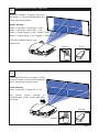
Switch from 16:9 to 2.35:1 (fig. G-H)
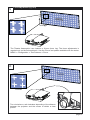
Press RCU button 1 or apply 0 Volt to the
RF-emitter to move the Anamorphic lens
out of the projector beam.
Scaler settings:
Menu -> Input AR -> Frame AR -> 16:9
Menu -> Input AR -> Active AR -> 1.78
Menu -> Output Setup -> Lens -> Mode 1-Auto
Menu -> Output Setup -> 12V Trigger2 -> THEATRE
The picture obtained has a 16:9
aspect ratio.
button 1
0 Volt
H
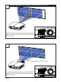
Press the RCU button 2 or apply 12 Volts
to the RF-emitter to move the Anamorphic
lens in front of the projector beam.
Scaler settings:
Menu -> Input AR -> Active AR -> 2.35
The
picture
format
changes
to
Cinemascope® (2,35:1 format) and fulfills
the screen.
12 Volts
button 2
page 11
I
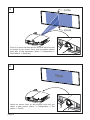
Horizontal alignment in 2.35:1 position, with Anamorphic Lens (fig. I-K)
If the Anamorphic Lens is not aligned with the projector
beam, the picture obtained is not centered into the
2.35:1 screen.
J
horizontal alignment screws
To align the picture with the screen, move the THEATRE
Lens on the horizontal axis until the projected picture
fulfills the screen.
page 12
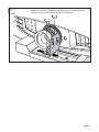
K
Locate the screws indicated below to set the horizontal alignment.
Tighten the screws when the setting is completed.
page 13
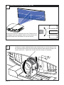
L
Setting vertical position and tilt (fig. L-M)
A pincushion distorsion appears when the Theatre lens is
not aligned with the projector beam on the vertical axis.
Use the Xhatch fine Test Pattern to set the lens tilt.
M
page 14
Locate the screws indicated below and release them to set the lens tilt. Set
the vertical position of the lens so that the projector beam passes through the
center of the lens. Tighten the screws when the setup is completed.
N
Focus adjustment (fig. N-O)
y
����������
x
Not focused on x-axis
The Theatre Anamorphic Lens features a 6-turns focus ring. The focus adjustments is
required only on the horizontal axis. Use the ‘Focus’ test pattern available with the scaler:
MENU -> Configuration -> Test Patterns -> Focus.
O
�����
Focused
Turn clockwise or anti-clockwise depending of the distance
between the projector and the screen to obtain a clear
picture.
page 15
Scaler settings and 12V Trigger configuration:
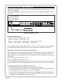
The output “12V Trigger#1” is active when the scaler is powered ON. It can control a screen
opening by example.
Connect the RF-Emitter supplied to the scaler output “12V Trigger#2” located at the back
of the unit.
12V Trigger#1
12V Trigger#2
I
N
P
U
T
OUTPUT
1
2
H DM I
INPUT
3
4
Y (G)
O
U
T
P
U
T
Pb (B)
Pr (R)
H
V
Y (G)
DC In
+6V @5A
ANALOG VIDEO
POWER
I 1
N
P
U
T
S 2
Pb (B)
Pr (R)
1
2
SYNC
COMPONENT
1
1
1
2
2
S-VIDEO
OUTPUT
INPUT
3
VIDEO
2
L
R
ANALOG AUDIO INPUT
4
D I G I TA L A U D I O
SERIAL PORT
RF-emitter
Back of the Master Three
Recommended settings:
Menu -> Input AR -> Frame AR -> 16:9
Menu -> Input AR -> Active AR -> 1.78
Menu -> Output Setup -> Aspect Ratio -> Lens -> Mode1-Auto
Menu -> Output Setup -> 12V Trigger2 -> THEATRE
Upon changing the Input Active AR to 2.35:1 or User -> 2.33 or greater, the 12V Trigger#2
is automatically switched to Active and a vertical stretching is applied to the picture.
Watching 16:9 and 2.35:1 movies on the same input
When projecting an animation movie which is in 16:9 format, you should set the Input Active
AR to 1.78 (16:9), the 12V Trigger#2 is Inactive, and no vertical stretching is applied.
Upon swapping the animation to a 2.35:1 Cinemascope® movie, change the Input Active
AR settings:
Menu -> Input AR -> Active AR -> 1.78
Menu -> Input AR -> Active AR -> 2.35
The 12V Trigger#2 becomes active and the Anamorphic Lens is driven before the projector
beam, the picture is also vertically stretched to get a perfect picture on the 2.35:1 screen.
Quick access buttons on the Remote Control Unit
“Aspect“ button features a direct access to the “Active AR” menu.
“16:9” button sets the Active AR to 1.78, removes the Anamorphic Lens and disable the
vertical stretch when 12V Trigger2 is set to “Theatre Mode“.
“Viewing Mode” button features a direct access to 12V Trigger2 menu: press sequentially
to switch the 12V Trigger2 to OFF, ON and THEATRE. The vertical stretching is
maintained if the Active AR is greater than 2.33:1
page 16
To get further information on the Master Three menus, THEATRE Mode and RS-232 codes,
please consult the scaler User Manual.
The scaler must have the 12V trigger optional card installed to have access to these
menus.
Watching a Cinemascope® movie with subtitles:
Subtitles are decoded by your DVD-player and incrusted into the signal flow sent to your
projector through its outputs. For this the reason, the subtitles position is determined by
your DVD-Player. Make sure that your DVD-Player can output subtitles into the active
frame when watching Cinemascope® movies.
1
2
subtitles are generally
located in the black bars
subtitles are generally
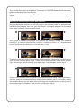
When using a standard DVD-player, the subtitles are generally located into the black
bars.(fig.1) If the DVD-player doesn’t feature a subtitles position, the Cinemascope®
picture would miss the characters in the black bars. (fig.2)
3
4
subtitles are generally
located in the black bars
subtitles are generally
located in the black bars
Thankfully, most of the DVD-Players handle subtitles position. Browse into your DVD-player
menu for the subtitles option menu. Change the subtitles position in the active picture.
(fig.3) No character will be missing when watching a Cinemascope® movie. (fig.4)
6
5
subtitles are generally
located in the black bars
subtitles are generally
located in the black bars
High-end DVD-Players feature a special “Stretched Mode” (also called “Anamorphic Mode”)
that can output an anamorphic picture with incrusted subtitles (fig.5). This mode renders
the subtitles directly into the active picture and they use a smaller portion of the picture to
be displayed (fig.6) compared to the previous configuration (fig.4)
page 17
2.40:1 movie into a 2.35:1 Cinemascope® screen:
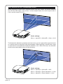
When projecting a movie with a different format from your screen, the picture obtained
won’t fill the total height of the screen. In the example below, the movie aspect ratio is
2.40:1 and the screen is 2.35:1.
Scaler settings:
Menu -> Input AR -> Active AR -> User -> 2.40
To eliminate the black bars projected onto the screen, you can apply either a general zoom
or a vertical zoom to the picture until they disappear. When applying a vertical zoom, keep
in mind that the recommended maximum distortion is 3%. Above this level, the distortion
would become perceptible and could be disturbing.
ZOOM
Scaler settings:
Menu -> Input AR -> Active AR -> 2.35
Menu -> Input AR -> Zoom Horizontal -> 1.000
Menu -> Input AR -> Zoom Vertical -> 1.021
page 18
page 19
Contact information
TEC - CineVERSUM
7, rue La Caille, 75017 Paris, France
Tel +33 1 42 29 44 44
Email [email protected]
www.cineversum.com
Part. No. R599752