1
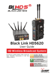
Black Link HD5
User Guide
HD Wireless Broadcast System
Kit ensures a stable wireless video, audio and
data * (RS-485) transmission in real time
(ZERO LATENCY).
www.camsat.com
Thank you for choosing the Black Link HD5. We are sure that you will benefit from its
unique features. Please read this instruction manual to safely operate and to maximize
performance.
The material contained in this manual consists of information that is the property of
CAMSAT Company, and is intended solely for the use by the purchasers of the equipment
described in this manual.
CAMSAT Company, prohibits the duplication of any portion of this manual or the use herein
for any application other that the operation or maintenance of the equipment described in
this manual without the expressed written permission of CAMSAT Company.
Black Link HD5 User Guide
1
MADE IN
POLAND
EU
Table of Contents
I Safety instructions and Maintenance................................................................................ 3
II Content................................................................................................................................. 6
1. Product overview.............................................................................................................. 6
2. Switches, connectors and LED indicators....................................................................... 6
3. Menu - Settings................................................................................................................ 7
III Kit start up............................................................................................................................ 8
1. Connection and start-up of the Black Link HD5 transmitter.......................................... 8
2. Connection and start-up of the Black Link HD5 receiver................................................ 9
3. Connection and establishing transmission between the transmitter and the receiver 9
4. Antennas setting at transmitter and receiver................................................................. 9
5. Visualization of radio wave propagation.........................................................................10
IV Technical Specifications
1. Connectors scheme.........................................................................................................10
2. Data transmission (RS-485) - specification and frequencies........................................11
3. Frequency table for video / audio transmission - transmitter BL-HD5610.................. 12
4. Frequency table for video / audio and data transmission - receiver BL-HD5000........12
5. Technical specifications of the transmitter BLHD5610..................................................13
6. Technical specifications of the receiver BLHD5000.......................................................14
7. Switches...........................................................................................................................15
8. Avalible versions..............................................................................................................15
V General terms and conditions of warranty.......................................................................16
VI Equipment disposal............................................................................................................ 17
Black Link HD5 User Guide
2
MADE IN
POLAND
EU
I. Safety instructions and Maintenance
To safely use our device, the instructions in this manual must be read and
respected.
Safety Symbols
Warning about the possible risk of high voltage exposure caused by the
presence of uninsulated dangerous voltage within the product enclosure.
!
Warning about the importance of specific instructions in manual.
Warning: the device can operate at frequencies and power, which may not be
permitted on the territory of selected countries.
The device is easily adaptable to any regional regulations in all fields of exploitation and
to meet the requirements of regional and national terms of frequency and law. 5GHz
band is divided into different work channels that can be used in each country or region
differently. Always check the frequency used and the type of antenna used. You should
always check the operating frequency and compliance with the regulations of the region
or country where the device is supposed to work.
Safety Instructions
* Before turning on the device antennas must be connected.
* Not using the instructions included in this manual may cause exposure to shock
and/or electrical or mechanical hazards.
* Use only the originally approved power supply adapter and use it according to its user
guide.
* Do not use the device in wet environment. Contact with water may cause danger of
electrical shock.
* Do not close the ventilation gaps.
* For cleaning use dry cloth only.
* Powered on device should be kept min. 30 cm from human body.
* Devices should be kept and used in moderate air moisture and temperature
(14–131⁰F or -10−55⁰C).
* Device is not supposed to be used outside in adverse weather conditions (rain, snow,
ice, etc.)
* Device is not supposed to be used or stored in excessive dust conditions, or high
humidity conditions.
* Do not use the device during storm. There is a risk of shock caused by lightning.
Black Link HD5 User Guide
3
MADE IN
POLAND
EU
Safety Instructions - continued
* Use only recommended or supplied by Camsat accessories. Using other kind of
products may cause worse operating parameters or even damage of device.
* Do not use the product if there is any physical damage to the enclosure.
* Device must not be modified, repaired or disassembled by yourself. In case of any
damage or operating problems contact your dealer or CAMSAT directly.
* In case of any unusual situations(like damage, smoke, smell, or other) immediately
contact your dealer or CAMSAT office.
* Device may become slightly hot while using. But if temperature of device becomes
unbearable to touch, turn off the device and contact our technical support.
* Avoid contact of the device with corrosive materials.
* Avoid contact of the device with fire.
* Do not place this product on an uneven or vibrating surface. It may cause malfunction or damage.
* Compliance is required referring to the voltage, frequency, and current according to
the requirements listed on the label and the manufacturer's instructions. Connecting
other power source than those specified in the manual may cause improper operation, damage to equipment or in case of not following the restrictions may constitute
a fire hazard.
* The operator or user can not replace any part of the device. Service must be provided only by a qualified technician or the manufacturer.
Power supply
1. Producer enables installation of the device in a special V-Lock interface of video
cameras, power from the V-Lock battery, and a dedicated power supply. Depending on the destination, a device installed with equipment other than a video
camera can cause problems with the device itself or other equipment.
For more information about the installation of equipment other than the video
camera, contact the representative of the manufacturer.
2. It is forbidden to connect battery and AC adapter to Black Link HD5 transmitter
or receiver at the same time. This configuration of power can damage the
device.
Black Link HD5 User Guide
4
MADE IN
POLAND
EU
! Potential Hazards
* Always obey local signs and law regulations. Using the device in restricted areas may
case danger.
* Do not use Black Link HD5 in areas with potential presence of explosive atmospheres.
Breaking this restriction may result with fire explosion and injury or even death.
* Usage of Black Link HD5 on petrol or service stations is not recommended. Users are
advised to obey all the warning and restriction signs referring to radio equipment in
fuel depots, chemical plants or other areas with potential explosion risk.
* Please be cautious with usage of Black Link HD5 in all places with potential danger of
explosion (even if area is not marked). It refers to places like: gas stations, below
deck on boats, chemical transfer or storage facilities, vehicles using liquefied petroleum gas (such as propane or butane), areas where the air contains chemicals or
particles, such as grain, dust or metal powders and any other area where it would
normally be advisable to turn off a vehicle’s engine.
* Do not use Black Link HD5 near medical or life support equipment that could be
influences by radio interference. The Black Link HD5 unit may transmit signals that
could interfere with this equipment.
Distances, interferences
1. The transmission distance may vary depending on the frequency, environment,
the conditions of radio waves, buildings, weather conditions, etc.
2. When the transmitter is positioned near appliances such as a TV, a wireless
network R-LAN, another transmitter or placed between other radio devices
this video may not be transmitted correctly or devices may lose the connection.
When this happens you should increase the distance between disturbed devices
and the transmitter.
3. Signal reception can vary depending on the height and angle of the transmitter.
If the reception is not stable you should optimize antennas settings.
4. Meteorological radars operating at frequencies 5250-5350 MHz and 5650-5850
MHz are priority users. These radars could cause interference or prevent its
proper operation.
Warning
Antennas used in transmission from this transmitter must be installed in accordance
with instruction and should be placed at a distance of at least 30cm from all
persons. The transmitter can not be operated in conjunction with any other
antenna or transmitter.
Black Link HD5 User Guide
5
MADE IN
POLAND
EU
II Content
1. Product overview
BLACK LINK HD5 set is an integrated transmission system for image at high HD
resolution (1080p, 1080i, 720p) and sound, designed for operators of television cameras
HD-TV. The system is characterized by a lack of transmission delay (<1ms) and no image
compression. The devices were also equipped with wireless data transmission system
RS-485, which can be used to remotely set camera parameters, communication with the
director etc.
With TALLY it is possible to inform the camera operator or the person filmed about
from which camera signal is transmitted. In addition, the camera operator may be
informed about the strength of the radio signal.
Features:
* Supported HD-SDI / SD-SDI input and output.
* Transmitting HD video (1080i, 1080p, 720p) and SD video (525i/625i)
* Supporting SDI embedded audio. (Audio CH1 and CH2 only)
* Transmission delay is less than 1msec.
* Manual selection of transmitted frequencies.
* Power can be supplied either by V-Mount or Anton Bauer type Lithium Ion battery or
by EXT DC via XLR 3P connector.
* Two spare ports NO / NC for use according to your needs.
2. Switches, connectors and LED indicators
TRANSMITTER
Power connector miniXLR
Power connector miniXLR
Controls (K Group)
Data RS-485 Socket
Data RS-485 Socket
HDMI OUT Socket
TALLY Output
TALLY Output
TALLY IN Socket
HDMI IN Socket
power (PWR)
TALLY LED / LINK LED Socket
data transmission (DATA)
OLED Display
indicates the connection between
transmitter and receiver ( LINK )
Radio Signal Strength
Very low signal
Low signal
Good signal
Very good signal
6
RECEIVER
Black Link HD5 User Guide
MADE IN
POLAND
EU
3. Menu - settings
ENTERING MENU
To enter the Menu push and hold
MENU NAVIGATION
To move through menu use buttons:
down / left
up / right
select
back/cancel/stand by
MENU TREE
Channel (operating frequency selection)
Allows to select the requency on which the transmission will be executed. Possible choice of 10
predefined settings or manual frequency selection.
The same frequency should be set for transmitter and receiver!
Video input (signal source selection) *Tx
Selection of socket type (SDI or HDMI), to which signal from camera will be transferred.
Temperature
Information about current device temperature
Settings
Data settings | **
Setting data transmission speed (baud rate) and data format
Tally settings (option available only for receiver in Master mode)
Enables selection of Tally operating mode (Open Collector Mode/Logic) turning it off.
Tally turned off causes no signal strength information on receiver and transmitter.
Buzzer settings
Turn on/off the notification of signal losing
RSSI icon set
Setting the signal strength information type
Tx select | *Rx
Select type of transmitter sending signal to receiver
Receiver mode | *Rx
Setting receiver mode . In situation when transmitter sends signal to multiple receivers
one of them must operate in Master mode, and the rest of them in Slave mode
Factory reset
Back to factory settings
Device information
Information about device serial numer
*RX Option available only in receiver
*TX Option available only in transmitter
** Option available in devices with data transmission module
Black Link HD5 User Guide
7
MADE IN
POLAND
EU
III Kit start up
1. Connection and start-up of the Black Link HD5 transmitter
TRANSMITTER
a) Before switching on the unit connect the BL-AP antennas to the connectors
SMA ANTENNA 1 and 2 and BL-AD antenna to the SMA ANTENNA DATA connector.
b) Connect the power supply using a battery pack with V-LOCK socket (to power on devices use the switch on the V-LOCK plug) or AC PX-12/2 12V DC with mini XLR ending to
the socket (unit turns on automatically when you connect power supply).
c) Connect the transmitter to the image transmitting device (camera) to the
SDI IN
or HDMI IN . You can also connect the wires to both sockets
and
, however, the signal will be transmitted to the receiver with only one slot (active slot
selected in the menu (See page 7 Main Menu - Video Input).
SDI OUT connector is for example used to connect an external monitor, to which image
will be forwarded from the SDI OUT
(active loop through).
d) Set the operating channel (frequency), which will be used for transmission
(See page 7, Main menu - Channel).
After turning on the device, the PWR LED lights up, indicating that the device is running.
The screen will show status of:
Selected channel or frequency
(if manual selection)
Signal strenght in dB
or as wave sign
Resolution
Status:
OK - connected
NO LINK - not connected
Selected signal source
Black Link HD5 User Guide
8
MADE IN
POLAND
EU
2. Connection and start-up of the Black Link HD5 receiver
RECEIVER
a) Before switching on the unit connect the BL-AP antennas to the connectors
SMA ANTENNA 1,2,3,4,5 and BL-AD antenna to the SMA ANTENNA DATA connector.
b) Connect power using the included AC adapter with the MINI XLR 3P ending
to the socket
(unit turns on automatically after power).
c) Connect the devices receiving a/v signal to SDI OUT
and HDMI OUT
.
The signal is transmitted in parallel by all slots (no need of active socket selection).
d) Set the operating channel (the same as in the transmitter).
3. Connection and establishing transmission between the transmitter and the receiver
a) Before turning on the device you must connect the antennas first.
b) In order to obtain the highest transmission quality between the transmitter antennas
and the receiver it is necessary to preserve the optical visibility (LOS). In the lack of
optical visibility of antennas coverage may differ from the nominal.
c) In order to achieve the highest transmission quality it is advisable to keep a minimum
distance of 2 meters between devices.
d) The devices must be set to the same channel work.
4. Antennas setting in transmitter and receiver
TX
TX
Correct antennas setting in
transmitter
RX
RX
Correct antennas setting in
receiver
Optimal transmitter position
vs. Receiver
Black Link HD5 User Guide
9
MADE IN
POLAND
EU
5. Visualization of radio wave propagation
HIGHEST SIGNAL QUALITY
SIGNAL BLOCKED BY OBJECTS
IV Technical specification
1. Connectors schema
9-14V DC
N/C
+5V
+5V
+5V
+5V
A+
TALLY
OC Mode
TALLY IN
OC/Logic Mode
GND
RS-485
TALLY OUT
TALLY IN
12V DC
N/C
GND
GND
TALLY LED
B-
N/C
N/C
LINK
LED
TALLY
LED
GND
TALLY IN
TALLY control input signal operating in two modes (operating mode can be changed
in MENU).
Internal to IC
IC Output
Base
Input
External to IC
„Open”
Collector
IC Ground
a) Open Collector Mode
The control is done by connecting or disconnecting inputs ( TALLY IN)
to ground (GND).
b) Logic Mode (Logical Mode zero-one)
Control is done by giving logic one or zero:
. zero = 0V
. one = +5V.
TALLY OUT
Open Collector Output to control the TALLY indicators . The signal is shorted
to GND.
Maximum current: 200mA / 12V.
Black Link HD5 User Guide
10
MADE IN
POLAND
EU
2. Data transmission (RS-485) - specification and frequencies
Table 1 - Specification
Parameter
Description
Modulation
GFSK
Occupied Bandwidth
20 kHz
Distance between the channels
50 kHz
Frequency
from 869,4 to 869,65 MHz
Power
14dBm (25mW)
Data formats
8n1, 8o1, 8e1
Baud rate
4800, 9600, 19200, 38400 [bps]
Table 2 - Frequencies
Frequencies in MHz
for video / audio
transmission
Frequencies in MHz
for data transmission
from
to
5190
5225
869,40
5230
5265
869,45
5270
5310
869,50
5510
5545
869,60
5550
5585
869,65
5590
5625
869,40
5630
5665
869,45
5670
5705
869,50
5710
5755
869,55
5760
5805
869,60
5810
5835
869,65
Black Link HD5 User Guide
11
MADE IN
POLAND
EU
3. Frequency table for video / audio transmission - transmitter BL-HD5610
Channel / Frequencies
Transmission
Usage
in MHz Description power
CH-1 / 5190
Non-DFS
CH-2 / 5230
Non-DFS
CH-10 / 5755
ISM; Non-DFS
CH-11 / 5795
ISM; Non-DFS
CH-12 / 5835
ISM; Non-DFS
CHFrequency
- Manual *bandwidth: Non-DFS
40MHz
14dBm EIRP
(25mW EIRP)
14dBm EIRP
(25mW EIRP)
14dBm EIRP
(25mW EIRP)
14dBm EIRP
(25mW EIRP)
14dBm EIRP
(25mW EIRP)
14dBm EIRP
(25mW EIRP)
Europe: Indoor only
max. 200mW EIRP
Europe: Indoor only
max. 200mW EIRP
USA: Indoor, outdoor
max. 25mW EIRP
USA: Indoor, outdoor
max. 25mW EIRP
USA: Indoor, outdoor
max. 25mW EIRP
NOTE: These settings use ONLY in accordance
with the country / region in which the transmitter
is supposed to work.
4. Frequency table for video / audio and data transmission - receiver BL-HD5000
Channel
CH-1
CH-2
CH-3
CH-4
CH-5
CH-6
CH-7
CH-8
CH-9
CH-10
CH-11
CH-12
CH - Manual *
Frequencies in MHz
for video / audio
transmission
5190
5230
5270
5310
5510
5550
5590
5630
5670
5755
5795
5835
CH - Manual *
Frequencies in MHz
for data transmission
Description
869,40
Only signal receiving
869,45
Only signal receiving
869,50
Only signal receiving
869,55
Only signal receiving
869,60
Only signal receiving
869,65
Only signal receiving
869,40
Only signal receiving
869,45
Only signal receiving
869,50
Only signal receiving
869,55
Only signal receiving
869,60
Only signal receiving
869,65
Only signal receiving
Check Table 2 - Frequencies
Only signal receiving
on page 11
* CH - Manual – Possibility of using specific channels and frequency ranges
(
non DFS Mode). Depend on country and region! You should obey the regulations
of given country. Do not use this setting if you are not sure what standards are valid in
your region.
Black Link HD5 User Guide
12
MADE IN
POLAND
EU
5. Technical specifications of the transmitter BLHD5610
TECHNICAL SPECIFICATION - TRANSMITTER
Video - Audio
Video input signal
SD-SDI(SMPTE 259M-C) / HD-SDI(SMPTE 292M)
HDMI
Audio input signal
SDI Embedded (Embedded Audio CH1,CH2)
Monitoring
SD-SDI/HD-SDI through out
Video Format
HD: 4:2:2 YCbCr 10bit
1080i @ 50/60 Hz,
1080p @ 24/25/30/50/60 Hz
720p @ 50/60 Hz
SD: 4:2:2 YCbCr 10bit
525i/59.94, 625i/50
Input / Output
Video input
BNC ×1 (SD-SDI/HD-SDI)
HDMI
Video output
BNC ×1 (SD-SDI/HD-SDI / Loop through out)
Battery input **
V-Mount ×1
DC power output **
V-Plate ×1
Ext-DC input
DATA RS-485 **
TALLY OUT **
TALLY LED / LINK LED **
mini XLR (3 pins) (scheme at page 11)
Pin 1: 9-14V DC
Pin 2: N/C
Pin 3: GND
mini XLR (5 pins) (scheme at page 11)
Pin 1: A+
Pin 4: BPin 2,3,5: N/C
mini XLR (4 pins) (scheme at page 11)
Pin 1,3: +5V
Pin 2: GND
Pin 4: TALLY
mini Jack 3,5mm (scheme at page 11)
1: Link LED
2: TALLY LED
3: GND
Wireless transmission
Transmission power
EU Region: Power 14dBm / EIRP
Transmission distance
600m (LOS - Line of Sight)
Transmission delay
No delay (less than 1 ms.)
Transmission format
MIMO / OFDM
Antenna
SMA-RP x 2 + (SMA x 1) *
Link mode
Broadcast
Power
Power consumption
12W
Power input
12V DC via a 3-pin miniXLR
Power input **
9-14V DC via a battery socket (V-Lock or other)
Power output **
Through-out the DC power only if powered by battery
3URGXFWVSHFL̬FDWLRQ
Dimension
190 × 127 × 54mm / 190 × 127 × 90mm **
Weight
761g / 1020g **
Operating temperature
from -10°C to 55°C
5HJXODWLRQ&HUWL̬FDWLRQ
EN 301 489-3 V1.6.1 (2013-08)
EN 301 489-17 V2.1.1 (2012-09)
EN 301 489-1 V1.9.2 (2012-10)
EN 300 440-2 V1.4.1 (2010-08)
EN 301 893 V1.6.1 (2011-11)
EN 62311:2008
* - referes to: BL-HD5610-K3 and BL-HD5610-K4
** - referes to: BL-HD5610-K2, BL-HD5610-K3 and BL-HD5610-K4
13
EN 300 220-1 V2.4.1 (2012-05) **
EN 300 220-2 V2.4.1 (2012-05) **
EN 60950-1:2006 + A11:2009 + A1:2010 **
EN 62479:2010 **
RoHS
Black Link HD5 User Guide
MADE IN
POLAND
EU
6. Technical specifications of the receiver BLHD5000
TECHNICAL SPECIFICATION - RECIVER
Video - Audio
Video output signal
SD-SDI(SMPTE 259M-C) / HD-SDI(SMPTE 292M)
HDMI
Audio input signal
SDI Embedded (Embedded Audio CH1,CH2)
Monitoring
SD-SDI/HD-SDI through out
Video Format
HD: 4:2:2 YCbCr 10bit
1080i @ 50/60 Hz,
1080p @ 24/25/30/50/60 Hz
720p @ 50/60 Hz
SD: 4:2:2 YCbCr 10bit
525i/59.94, 625i/50
Input / Output
Video output
BNC ×2 (SD-SDI/HD-SDI)
HDMI
Battery input **
V-Mount ×1
DC power output **
V-Plate ×1
Ext-DC input
DATA RS-485 **
TALLY IN **
mini XLR (3 pins) (scheme at page 11)
Pin 1: 9-14V DC
Pin 2: N/C
Pin 3: GND
mini XLR (5 pins) (scheme at page 11)
Pin 1: A+
Pin 4: BPin 2,3,5: N/C
mini XLR (4 pins) (scheme at page 11)
Pin 1,3: +5V
Pin 2: GND
Pin 4: TALLY
Wireless transmission
Transmission power
EU Region: Power 18dBm / EIRP
Transmission distance
600m (LOS - Line of Sight)
Transmission delay
No delay (less than 1 ms.)
Transmission format
MIMO / OFDM
Antenna
SMA x 5 ( Downlink Antenna 1/2/3/4/5) + (SMA x 1) *
Link mode
Broadcast
Power
Power consumption
12W
Power input
12V DC via a 3-pin miniXLR
Battery mount **
9-14V DC via a battery socket (V-Lock or other)
Power output **
Through-out the DC power only if powered by battery
3URGXFWVSHFL̬FDWLRQ
Dimension
190 × 127 × 54mm / 190 × 127 × 90mm **
Weight
761g / 1020g **
Operating temperature
from -10°C to 55°C
5HJXODWLRQ&HUWL̬FDWLRQ
EN 301 489-17 V2.1.1 (2009-05)
EN 301 489-1 V1.9.1 (2011-09)
EN 301 489-3 V1.4.2 (2002-08)
EN 301 893 V1.5.1 (2008-12)
EN 300 220-1 V2.4.1 (2012-05) **
EN 301 220-2 V2.4.1 (2012-05) **
EN 60950-1:2006 + A11:2009 + A1:2010 **
EN 62479:2010 **
RoHS
* - referes to: BL-HD5610-K3 and BL-HD5610-K4
** - referes to: BL-HD5610-K2, BL-HD5610-K3 and BL-HD5610-K4
Black Link HD5 User Guide
14
MADE IN
POLAND
EU
7. Switches
SWITCHES - OPERATORS IN TRANSMITTER AND RECEIVER
Led indicators
Status indicators
Signal strength *
RED - power (PWR)
GREEN - data transmission (DATA)
BLUE - indicates connection between transmitter and receiver (LINK)
Very low signal
Low signal
Good signal
Very good signal
Operators (K Group) - scheme at page 6
Down / Left
Up / Right
OK
BACK /
Enter to menu / Select
Back / Stand By
Other switches
Power switch **
Power ON/OFF
* - referes to: BL-HD5610-K2, BL-HD5610-K3 and BL-HD5610-K4
* - only in transmitters with Data / in every receiver
8. Avalible versions
AVALIBLE SETS OF BLACK LINK HD5
Set name
BL-HD5610-K1
BL-HD5610-K2
BL-HD5610-K3
BL-HD5610-K4
Compatible with V-Lock
or Anton Bauer batteries
+
+
+
+
+
+
+
+
+
+
+
Transmitter compatible
with V-Lock or Anton
Bauer camera mount
+
+
+
Half-duplex RS-485 Data
Transmission
TALLY LED
LINK LED
Optical and sound
out-of-range alerts
Receiver compatible with
V-Lock or Anton Bauer
camera mount
Sets includes
+
- TX BL-HD5610-T1
- RX BL-HD5000-R1
- Ant. BL-AP x 7 pieces
- Power Supply CX-12/2
- User manual
- Declaration of conformity
- TX BL-HD5610-T2
- RX BL-HD5000-R1
- Ant. BL-AP x 7 pieces
- Power Supply CX-12/2
- User manual
- Declaration of conformity
- TX BL-HD5610-T3
- RX BL-HD5000-R3
- Ant. BL-AP x 7 pieces
- Ant. BL-AD x 2 pieces
- Power Supply CX-12/2
- User manual
- Declaration of conformity
- TX BL-HD5610-T3
- RX BL-HD5000-R4
- Ant. BL-AP x 7 pieces
- Ant. BL-AD x 2 pieces
- Power Supply CX-12/2
- User manual
- Declaration of conformity
TX - Transmitter
RX - Receiver
Ant. - Antenna
Black Link HD5 User Guide
15
MADE IN
POLAND
EU
V General warranty terms
The device is supplied with a standard warranty card. The manufacturer declines
all other warranties. In no case the producer is liable for any damages (including, without
limitation, consequential, special, or incidental damages, or damages for loss of profits,
business interruption, loss of business information or other pecuniary loss) arising out of
the use or inability to use this product, even if the manufacturer has been advised of the
possibility of such damages.
Camsat grants a 24 month warranty for the Black Link HD5 transmission kit
1. If the device is not be operating properly, make sure, before returning the device for
servicing, that everything was done according to the operating manual
2. If the faulty device is returned or send in for repairs, a thorough written description of
the signs of the device’s faulty operation, including the operating environment and the
manner in which they appear, should be enclosed
3. The prerequisite for exercising the warranty rights is enclosing the proof of purchase,
including the purchase date and description of damage, with the faulty device
4. Warranty repairs cover only faults occurring due to reasons inherent to the sold device
5. Warranty repairs will be carried out in the shortest possible amount of time not exceeding 14 days, counting from the moment of accepting the device for servicing If parts need
to be imported, the repair deadline may be extended After the repairs have been carried
out, the warranty period will be extended by the repair time
6. The warrantor is not responsible for the loss of the device configuration settings resulting from device repair or malfunction
7. The warrantor may refuse to carry out warranty repairs or terminate the warranty if it is
determined that the seals placed on devices or components comprising it are damaged
8. All repair services resulting from
The warranty does not cover
1. Mechanical damage of devices and failures occurring due to fortuitous events, such as:
fire, power grid overvoltage, electrical discharges, power supply, effects of chemical
substances.
2. Damage occurring due to: improper handling of the device, using the device against its
intended use or the operating manual, customer’s negligence, improper use
(temperature, humidity, flooding, dust, sanding up, improper power supply voltage)
3. Claims on account of the technical parameters, if they are consistent with those
indicated by the manufacturer
4. Marks created during usage, such as scratches, soiling and localised wear are not
covered by warranty In cases not regulated by the terms of this warranty sheet, the
appropriate provisions of the Civil Code are applicableDevice
Black Link HD5 User Guide
16
MADE IN
POLAND
EU
VI Device disposal
The mark presented to the left informs that this electrical or electronic
device, after its use has ended, cannot be thrown together with
household refuse The device should be delivered to a specialised
collection point Detailed information about the closest collection point
is available from local authorities.
The proper disposal of this device allows for preserving precious resources and avoiding the
negative impact on health and environment, which may be endangered if the waste is handled improperly Improper waste disposal is subject to penalties provided for in the appropriate regulations
Black Link HD5 User Guide
17
MADE IN
POLAND
EU
Hereby, CAMSAT Gralak Przemyslaw declares that the product series Black Link HD5,
meets the essential requirements and other relevant provisions of Directive 1999/5 / EC.
The device is CE marked, which indicates compliance with the guidelines of the Directive.
The device can be sold and used for transmission in the 5 GHz band.
The frequency range can be adjusted using the settings in accordance with legal regulations in every country. It is your responsibility to be adequate settings of the complying with
the applicable laws in the country or region.
Warning about the possible risk of high voltage exposure caused by the
presence of uninsulated dangerous voltage within the product enclosure.
!
Warning about the importance of specific instructions in manual.
Warning: the device can operate at frequencies and power, which may not be
permitted on the territory of selected countries. You should obey the regulations of given country.
Producer:
CAMSAT Gralak Przemysław
Ul. Ogrodowa 2a
86-050 Solec Kujawski
Offer and information: www.blacklink-hd5.pl
Service: [email protected]
Black Link HD5 User Guide
MADE IN
POLAND
EU