1
Bar Code
and
Magnetic Stripe Reader
Model 2500
USER'S MANUAL
2190 Regal Parkway Euless, TX 76040
(817) 571-9015 (800) 648-4452 FAX (817) 685-6232
FCC NOTICE
WARNING: This equipment generates, uses and can radiate radio frequency
energy and if not installed and used in accordance with the instruction manual,
may cause interference to radio communications. It has been tested and found
to comply with the limits for a Class A computing device pursuant to Subpart J of
Part 15 FCC Rules, which are designed to provide reasonable protection against
such interference when operated in a commercial environment. Operation of
this equipment in a residential area is likely to cause interference in which case
the user at his own expense will be required to take whatever measures may be
required to correct the interference.
Rev 2.7a
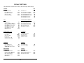
TABLE OF CONTENTS
Introduction .......................................................................................................... 1
Installation Instructions ........................................................................................ 2
Connecting the M2500 to the PC's Serial Port ...................................................... 8
Daisy Chain Instructions ...................................................................................... 9
Scanning Bar Codes .......................................................................................... 11
Wand Scanning ................................................................................... 11
Laser Scanning ................................................................................... 12
Installing and Using the MS941 Triggerless Laser ............................... 14
CCD Scanning .................................................................................... 20
Slot Reader (Badge Reader) ............................................................... 21
Scanning Magnetic Stripes/Cards ...................................................................... 22
Default Settings ................................................................................................. 23
Changing the Default Settings ............................................................................ 25
Programming Guide ........................................................................................... 27
Code 39 ............................................................................................... 28
UPC .................................................................................................... 29
EAN .................................................................................................... 30
UPC/EAN Supplements ...................................................................... 31
Interleaved 2 of 5 ................................................................................. 32
Codabar .............................................................................................. 33
Code 128 ............................................................................................. 33
Code 93 ............................................................................................... 34
Code 11 ............................................................................................... 34
MSI/Plessey ........................................................................................ 35
Serial Port ........................................................................................... 36
Preambles ........................................................................................... 39
Postambles ......................................................................................... 40
Termination Character ......................................................................... 41
Beep Length and Tone ........................................................................ 41
Mag Stripe Options #1 ......................................................................... 42
Mag Stripe Options #2 ......................................................................... 44
Bar Code Edit ...................................................................................... 46
Options #1 ........................................................................................... 47
Options #2 ........................................................................................... 49
Diagnostics ......................................................................................... 50
Cloning Setup Information .................................................................... 51
Specifications ...................................................................................... 54
Signal Definitions ................................................................................. 55
Appendix A - Function & Special Keys ......................................................... A-1
Appendix B - External Power Supply Requirements .................................... B-1
Appendix C - Code 39 Specifications ........................................................... C-1
Appendix D - Full ASCII Extension to Code 39 ............................................. D-1
Appendix E - UPC Specifications ................................................................ E-1
Appendix F - EAN Specifications .................................................................. F-1
i
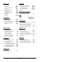
TABLE OF CONTENTS (Cont)
Appendix G
Appendix H
Appendix I
Appendix J
Appendix K
Appendix L
-
Interleaved 2 of 5 Specifications ............................................. G-1
Codabar Specifications .......................................................... H-1
Code 128 Specifications ........................................................... I-1
Code 93 Specifications ............................................................ J-1
Card Data Format for Transaction Cards ................................ K-1
Sources of Bar Code and Magnetic Stripe Standards .............. L-1
ii
INTRODUCTION
The Model 2500 bar code and magnetic stripe reader combines features found
in a variety of readers into one compact, easy to use system. The reader installs
quickly between the terminal and host computer. Data is sent to the computer
as if it were typed in from the terminal's keyboard. No software changes are
necessary.
The reader accepts a wide variety of input devices such as a LASER, CCD,
WAND, and MAGNETIC STRIPE READER. The Model 2500 allows up to three
input devices maximizing the versatility of the reader system.
Tailor the reader to individual applications by simply scanning a bar code from
the menu. Its that simple! All these features make the Model 2500 an ideal
data collection device that provides quality and performance in one package.
FEATURES:
Bar Code and Magnetic Stripe Data appear as Keyboard Data.
Reader Automatically Recognizes and Reads the following Bar Code
Types:
- Code 3 of 9 (Code 39)
CODABAR
- Extended Code 3 of 9 (Full ASCII)
Code 128
- Interleaved 2 of 5
Code 93
- UPC-A, UPC-E(0), UPC-E(1)
Code 11
- EAN-8, EAN-13
MSI/PLESSEY
- UPC & EAN Supplements
(2 and 5 Character)
Power/Ready Light Indicating Scanner Status
Reads Magnetic Stripes (Credit Cards, ID Cards, etc.)
Supports Multiple Input Devices (Lasers, CCD, Wand, Slot Reader)
1
INSTALLATION INSTRUCTIONS
OVERVIEW
Installation requires connecting cables between the reader, your computer, and
terminal.
NOTE:
Before installing the bar code reader, you must have an
operational RS-232 serial cable connected between the terminal
and host computer system. The terminal MUST be able to
communicate to the host system correctly BEFORE installing
the bar code reader.
Step 1:
Disconnect the existing RS-232 cable from the rear of the terminal. (This cable is the serial cable originally connected between
the terminal and host computer system).
Step 2:
The bar code reader comes with the following cable assemblies:
TERMINAL CABLE ASSEMBLY = 9 pin plug (male) to 25
pin plug (male)
HOST CABLE ASSEMBLY = 9 pin plug (male) to 25 pin
socket (female)
Plug the 9 pin end of the TERMINAL CABLE ASSEMBLY into the
connector labeled "TERMINAL" located on the rear panel of the
reader.
Step 3:
Plug the other end of the TERMINAL CABLE ASSEMBLY (the 25 pin
male) into the rear of the terminal labeled "MODEM" or "MAIN".
Step 4:
Plug the 9 pin end of the HOST CABLE ASSEMBLY into the
connector labeled "HOST" located on the rear panel of the reader.
Step 5:
Plug the other end of the HOST CABLE ASSEMBLY (the 25 pin
female) into the original serial cable that was removed from the
terminal.
2
Step 6:
CONNECTING INPUT DEVICES:
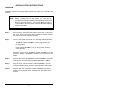
Installing A Wand
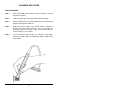
Plug the end of the WAND cable into the circular connector labeled
"WAND" on the front panel of the reader.
MICROSCANNER
AMERICAN
MICROSYSTEMS
LASER
WAND
MSR
POWER
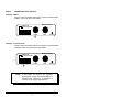
Installing A Laser Scanner
Plug the end of the LASER cable into the square connector labeled
"LASER" located on the front panel of the reader.
MICROSCANNER
AMERICAN
MICROSYSTEMS
LASER
NOTE:
WAND
MSR
POWER
A 12V LASER will require a 12V regulated
external power supply. See the APPENDIX at
the back of this manual for a description of
"External Power Supply Requirements".
3
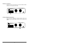
Installing A CCD Scanner
Plug the end of the CCD cable into the connector labeled "LASER"
located on the front panel of the reader.
MICROSCANNER
AMERICAN
MICROSYSTEMS
WAND
LASER
MSR
POWER
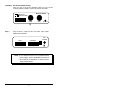
Installing A Magnetic Stripe Reader
Plug the end of the MAGNETIC STRIPE READER cable into the
circular connector labeled "MSR" located on the front panel of the
reader.
MICROSCANNER
AMERICAN
MICROSYSTEMS
LASER
WAND
4
MSR
POWER
Installing A Slot Reader (Badge Reader)
Plug the end of the SLOT READER cable into the circular
connector labeled "WAND" on the front panel of the reader.
MICROSCANNER
AMERICAN
MICROSYSTEMS
LASER
Step 7:
WAND
MSR
POWER
Plug the power supply into the rear panel of the reader
labeled "EXT POWER".
HOST
TERMINAL
EXT.
POWER
NOTE: A 12V LASER will require a 12V regulated external
power supply. See the APPENDIX at the back of
this manual for a description of "External Power
Supply Requirements".
5
Step 8:
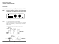
Verify that the cables are connected as shown below:
ORIGINAL
SYSTEM
CABLE
"TERMINAL"
CABLE
ASSEMBLY
"HOST" CABLE
ASSEMBLY
WAND
BAR CODE READER
ELECTRONICS UNIT
"HOST"
PORT
"TERMINAL"
PORT
6
HOST
COMPUTER
SYSTEM
POWER
SUPPLY
Step 9:
With the power supply connected, the "POWER" display on the
front panel of the reader will display RED and the reader will BEEP
twice. Approximately 1/2 second later the display will change to
GREEN.
Step 10:
If the reader has been installed correctly, you should be able to
type on the terminal's keyboard and communicate with the host
computer system.
Step 11:
The bar code reader is now operational and ready to use. The
terminal is fully functional and you may enter data via the keyboard
like you did prior to installation. To enter bar code data, simply
scan the bar code and the data will be transmitted to the host
system just like it was typed in from the terminal's keyboard.
Step 12:
The reader is shipped from the factory with the serial port
parameters set to the following defaults:
BAUD RATE:
DATA BITS:
PARITY:
OUTPUT DATA:
DUPLEX MODE:
9600
8
NONE
ASCII
FULL
NOTE: The reader's serial port parameters must be set
to match the terminal. Check your terminal's
serial port parameters against those listed above.
If any parameters are different, the reader must
be set to match the terminal. Proceed to the
section of the manual entitled CHANGING THE
DEFAULT SETTINGS.
7
CONNECTING THE MODEL 2500 TO THE PC'S SERIAL PORT
The Model 2500 can be connected to the PC's serial port and used as a
standard RS-232 serial scanner.
Step 1:
The bar code reader comes with two cable assemblies:
TERMINAL CABLE ASSEMBLY:
9 pin plug (male) to 25
pin plug (male)
HOST CABLE ASSEMBLY:
9 pin plug (male) to 25
pin socket (female)
To connect the bar code reader to the PC's serial port, only the
HOST CABLE ASSEMBLY will be used. Plug the 9 pin end of the
HOST CABLE ASSEMBLY into the connector labeled
"TERMINAL" located on the rear panel of the bar code reader.
Step 2:
Plug the other end of the HOST CABLE ASSEMBLY (the
25 pin female) into the PC's serial port (either COM1 or COM2).
Step 3:
Set the bar code reader to HALF DUPLEX MODE.
(See the Programming Guide section of the USER'S MANUAL).
Step 4:
The SOFTCOM utility program is included with the Model
2500 which enables RS-232 serial data to appear as keyboard
data to the PC. To install SOFTCOM on your PC, you must
perform the following steps:
- Insert the SOFTCOM diskette into drive A on the PC.
- At the DOS prompt (C:>), type A: and press ENTER.
- At the A:> prompt, type INSTALL and press ENTER.
Step 5:
Run the configuration program SCONFIG and set the serial
port parameters to match those of the bar code reader.
Step 6:
Run the program SOFTCOM. With SOFTCOM loaded, any
data scanned with the bar code reader will appear as
keyboard data to your program.
8
DAISY CHAIN INSTRUCTIONS
Daisy Chaining UsingSOFTCOM Keyboard Emulation Software to Poll M2500's
1.
2.
Set SOFTCOM keyboard emulation software for daisy chaining.
Program each M2500 decoder with a unique daisy chain ID.
Daisy Chaining Using SOFTCOM Keyboard Emulation Software and a Master
M2500 to Poll the Other M2500's in the Daisy Chain
1.
2.
Do not set SOFTCOM for daisy chaining.
Program the 1st M2500 (MASTER) to be the daisy chain Master Controller.
3.
Program each daisy chained M2500 decoder with a unique daisy chain ID.
NOTE: The MASTER M2500 cannot be used for data entry.
Daisy Chaining Using an M2000/M2002 to Poll the M2500's in the Daisy Chain
1.
2.
Program the M2000/M2002 to be the Daisy Chain Master Controller.
Program each M2500 decoder with a unique daisy chain ID.
NOTE: Under most circumstances the M2000/M2002 should have the
serial port programmed for 'PASS THROUGH' mode.
Daisy Chaining Using Your Own Polling Software
1. Each transmitted ID must be followed with a CARRIAGE RETURN <CR>.
2. If the decoder that is being polled has any data, it begins transmitting data
within 2 characters time at the current baud rate.
EXAMPLE:
Using 9600,N,8,1 as the Serial Port Parameters.
The decoder has an ID of '1', so the polling software
sends a '1' + <CR> and waits for at least (104 * 11 *2)=
2288 microseconds for the decoder box to start sending
data. If the decoder box does not start sending data,
then start the polling sequence for the next decoder. If
data is received, allow a delay of 50 milliseconds
following the last data character before polling again.
9
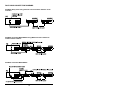
DAISY CHAIN CONNECTION DIAGRAMS
PC-M2500 Daisy Chain Using Softcom Communications Software as the
Controller
PC-M2500 Controller-M2500-M2500 Using M2500 Controller & Softcom
Communication Software
PC-M2000 Controller-M2500-M2500
10
SCANNING BAR CODES
WAND SCANNING
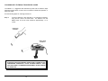
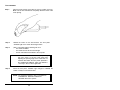
Step 1:
HOLD THE WAND LIKE A PENCIL, tilted at an angle of 10 to 30
degrees from vertical.
Step 2:
TOUCH the wand tip to the WHITE SPACE before the label.
Step 3:
Move the wand QUICKLY across the label as if you were drawing a
straight line through the middle of it.
Step 4:
Begin and end your stroke in the WHITE SPACE. Maintain a
smooth, even stroke while scanning. You can read labels bidirectionally (either left-to-right or right-to-left) and the data will
output correctly to your computer.
Step 5:
If you scanned the label correctly, you will hear a short BEEP.
When the "POWER" light turns GREEN the reader is ready to scan
another label.
11
LASER SCANNING
**CAUTION**
ALTHOUGH THE LIGHT EMITTED FROM CLASS II AND CLASS IIA
LASERS IS NOT CONSIDERED HAZARDOUS, AVOID STARING
DIRECTLY INTO THE LIGHT BEAM. EXTENDED EXPOSURE MAY
CAUSE DAMAGE TO YOUR EYES.
Step 1:
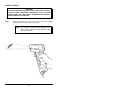
AIM the LASER at a bar code label. Hold the LASER
approximately 3 to 6 inches from the label.
NOTE: The maximum scanning distance depends on the
label density. Typical scanning distances vary
from 3 to 18 inches.
12
Step 2:
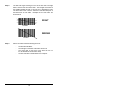
SQUEEZE the TRIGGER on the laser. The front panel "POWER"
light on the reader will change to RED and the "SCAN" light on the
back of the laser will turn on. Simultaneously the laser will emit a
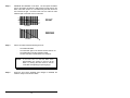
thin red beam of light. The beam must cover the entire bar code
label and part of the white area on both sides.
RIGHT
123456
WRONG
123456
Step 3:
After a successful read the following will occur:
-
The reader will BEEP.
The "DECODE" light on the back of the laser will turn on.
The reader will turn off the red beam of light.
The bar code data is transmitted to the computer.
NOTE:
Step 4:
If the laser has not read the label within
approximately one second, it will turn off the
beam. Try moving the laser closer to the bar
code label and adjusting the pointing angle.
When the front panel "POWER" light changes to GREEN, the
reader is ready to scan another label.
13
INSTALLING AND USING
THE MS941 TRIGGERLESS LASER
INSTALLATION
After installing the decoder box according to the instructions in the general
"Installation Instructions" section, you are ready to connect the laser.
Step 1:
Plug the end of the laser's cable into the square connector labeled
"LASER" located on the front panel of the reader. See the diagram
below:
MICROSCANNER
AMERICAN
MICROSYSTEMS
LASER
Step 2:
WAND
MSR
POWER
For "hands-free" scanning, note the following:
The cradle can be removed from the stand and set on a horizontal
surface (on its rubber feet), or mounted directly to a horizontal or
vertical surface.
The cradle has magnets which hold the LASER in place.
VERTICAL
COUNTER MOUNT
VERTICAL
WALL MOUNT
HANDS-FREE
SCANNING
STAND
HAND-HELD
HORIZONTAL
COUNTER MOUNT
HANDS-FREE
14
SCANNING WITH THE MS941 TRIGGERLESS LASER
The MS941 is a triggerless laser activated by a bar code or reflective object
passing through its beam. It can be set in its cradle for "hands-free"operation, or
held in the hand.
See the following steps for scanning instructions:
Step 1:
Point the LASER at a bar code label or, for hands-free scanning,
bring the bar code to the laser beam. The distance from the
MS941 laser to the bar code should be approximately 1 to 5
inches.
HAND-HELD
SCANNING
HANDS-FREE
SCANNING
**CAUTION**
ALTHOUGH THE LIGHT EMITTED FROM CLASS II LASERS IS NOT
CONSIDERED HAZARDOUS, AVOID STARING DIRECTLY INTO
THE LIGHT BEAM. EXTENDED EXPOSURE MAY CAUSE DAMAGE
TO YOUR EYES.
15
Step 2:
The laser will begin scanning as soon as the bar code is brought
within 5 inches of the front of the laser. The red light on the back of
the LASER's handle will stay on as long as it is attempting a read.
The laser beam must cover the entire bar code label and part of
the blank area on both sides. Examples of bar code scans are
shown below:
RIGHT
123456
WRONG
123456
Step 3:
After a successful read the following will occur:
-
The decoder will BEEP.
The red light on the back of the laser will turn off.
The green light on the back of the laser will turn on
for the duration of the decoder's beep.
The bar code data is transmitted to the computer.
16
SCANNING THE READER SETUP MENU WITH
THE MS941 TRIGGERLESS LASER
In setting up the MS941 laser, using a wand or trigger-activated input device
is recommended for scanning the READER SETUP MENU. If you do not have
such an input device, you can use the MS941 Laser.
To facilitate using the MS941 in reading the MENU, the following suggestions
are provided:
1)
2)
Curl the READER SETUP MENU from right to left (or the
reverse), so that only one column of bar codes is exposed to
the laser at a time.
OR
Use sheets of paper to cover bar codes adjacent to the one
that is to be scanned.
NOTE: See the "Changing the Default Settings" section
for detailed instructions on changing the settings.
SETTING UP THE MS941 TRIGGERLESS LASER
There are three separate modes of operation for the MS941 Laser. Descriptions of
the operation and setup of each mode follow:
NON-CONTINUOUS SCANNING - DEFAULT MODE
Recommended Usage:
Recommended for general use. However, this mode requires the laser
beam to be removed from any reflective surface between scans.
Operation Description:
The laser will power ON when it is brought within 5 inches of a reflective
surface. It will scan until it reads the bar code, or reaches the time
period specified in the LASER/CCD TIMEOUT option (the default is 1
second) before shutting off. For the next scan, the laser must momentarily be pointed away from any reflective surface, then brought back.
RE-READS: Accepts a re-read in the same manner as any other
read.
17
Settings:
The following settings, which are the defaults, apply to this mode of
operation:
Laser/CCD Timeout
Laser/CCD Trigger Shutoff
Laser/CCD Continuous Run
1-9 sec
ON
OFF
CONTINUOUS SCANNING - REFLECTIVE SURFACE REQUIRED
Recommended Usage:
Recommended for most applications; a highly efficient mode. Note
that it is NOT recommended if the laser is constantly exposed to a
reflective surface, such as a white counter top.
Operation Description:
The laser will power ON when it is brought within 5 inches of a reflective
surface, and will continuously scan and read one bar code after
another, until pointed away from any reflective surface. When pointed
away from a reflective surface, the laser will continue to scan for the
number of seconds specified in the LASER/CCD TIMEOUT option (the
default is 1 second) before it shuts off.
RE-READS:
Accepts a re-read after the amount of time specified
in the CONTINUOUS RUN READ DELAY option (the
default is 1 second) has passed.
Settings:
The following settings apply to this mode of operation:
Laser/CCD Timeout
1-9 sec
Laser/CCD Trigger Shutoff
ON
Laser/CCD Continuous Run
ON
Continuous Run Read Delay 0.1-9.9 sec
For optimum "hands-free" performance, set the LASER/CCD
TIMEOUT option at 3-4 seconds.
18
CONTINUOUS SCANNING
NON-REFLECTIVE SURFACES ACCEPTED, "BLINK" MODE
Recommended Usage:
Recommended to be especially useful when there are non-reflective
or colored scanning surfaces, or when bar code tags are small in size.
Note that with this mode, any other bar code input devices that are
connected to the decoder box will NOT operate.
Operation Description:
The laser will pulse on and off approximately two times a second. It will
stop pulsing and scan continuously whenever it is brought within 5
inches of a bar code, and it will immediately read one bar code after
another. When the laser is not exposed to any bar codes, it will
continue to scan for the number of seconds specified in the LASER/
CCD TIMEOUT option (the default is 1 second) before it resumes
pulsing the beam on and off.
RE-READS:
Accepts a re-read after the amount of time specified
in the CONTINUOUS RUN READ DELAY option (the
default is 1 second) has passed.
Settings:
The following settings apply to this mode of operation:
Laser/CCD Timeout
Laser/CCD Trigger Shutoff
Laser/CCD Continuous Run
Continuous Run Read Delay
1-9 sec
OFF
ON
0.1-9.9 sec
For optimum "hands-free" performance, set the LASER/CCD
TIMEOUT option at 3-4 seconds.
19
CCD SCANNING
Step 1:
Place the CCD scanner on the label or close to it (within one inch).
Make sure the bar code label fits completely within the frame of the
CCD opening.
Step 2:
PRESS the button on the CCD scanner. The front panel
"POWER" light on the reader will change to RED.
Step 3:
After a successful read the following will occur:
The reader will BEEP.
The reader will turn off the red CCD light.
The bar code data is transmitted to the computer.
NOTE: If a read does not occur immediately, try moving
the CCD closer to the bar code label and
adjusting the pointing angle. If the reader has not
read the label within the time period specified in
the LASER/CCD TIMEOUT option (the default is
1 second), it will turn off the light beam.
Step 4:
When the front panel "POWER" light changes to GREEN, the
reader is ready to scan another label.
NOTE: For triggerless operation, refer to "LASER/CCD
CONTINUOUS RUN and LASER/CCD
TRIGGER SHUTOFF" options.
20
SLOT READER (Badge Reader)
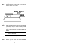
Step 1:
Hold the CARD so that the bar code label is on the bottom and
FACES the ARROW on the slot reader.
VIDEO WORLD
ID CARD
837611
Step 2:
Insert the CARD into the opening on either side of the reader.
Step 3:
Holding the CARD flat against the bottom of the reader, SLIDE the
card through the opening. You can slide the CARD bi-directionally
(either left-to-right or right to left) and the data will output correctly
to your computer. The CARD must maintain contact with the base
of the reader while scanning. The front panel "POWER" light will
change to RED while the card is being pulled through the SLOT
READER.
NOTE: The center of the bar code must be positioned 0.5" from
the bottom edge of the card.
Step 4:
After a successful read the following will occur:
The reader will BEEP.
The bar code data is transmitted to the computer.
Step 5:
When the front panel "POWER" light changes to GREEN, the
reader is ready to scan another card.
21
SCANNING MAGNETIC STRIPES/CARDS
MAGNETIC STRIPE READER
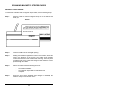
To read a bar code label with a magnetic stripe reader, see the following steps:
Step 1:
Hold the CARD so that the magnetic stripe is on the bottom and
faces you.
Step 2:
Insert the CARD into the enlarged opening.
Step 3:
Holding the CARD flat against the bottom of the reader, SLIDE the
card in the direction of the arrows. The CARD must maintain
contact with the base of the reader while scanning. The front panel
"POWER" light on the reader will change to RED while the card is
pulled through the reader.
Step 4:
After a successful read the following will occur:
-
Step 5:
The reader will BEEP.
The magnetic stripe data is transmitted to the
computer.
When the front panel "POWER" light changes to GREEN, the
reader is ready to scan another card.
22
DEFAULT SETTINGS
The Model 2500 is shipped from the factory with the following default settings:
CODE 39
UPC
CODE 39 DECODER
FULL ASCII EXTENSION
MOD 43 CHECK DIGIT
SEND CHECK DIGIT
CONCATENATE MODE
ON
OFF
OFF
OFF
OFF
UPC DECODER
CONVERT UPC-E TO UPC-A
CONVERT UPC-A TO EAN-13
SEND UPC-A NUMBER S YSTEM
SEND UPC-E NUMBER S YSTEM
SEND UPC-A CHECK DIGIT
SEND UPC-E CHECK DIGIT
EAN
UPC/EAN SUPPLEMENTS
EAN DECODER
ZERO FILL EAN-8 TO EAN-13
SEND EAN-13 COUNTRY CODE
SEND EAN-8 COUNTRY CODE
SEND EAN-13 CHECK DIGIT
SEND EAN-8 CHECK DIGIT
ISBN CONVERSION
INTERLEAVED 2
ON
OFF
OFF
ON
ON
ON
ON
OF
ON
OFF
ON
ON
ON
ON
OFF
SUPPLEMENTS D ECODER
ALLOW 2 D IGIT SUPPLEMENTS
ALLOW 5 D IGIT SUPPLEMENTS
REQUIRE SUPPLEMENTS
SEND SEPARATOR SPACE
5
INT. 2 OF 5 DECODER
CHECK DIGIT
SEND CHECK DIGIT
FIXED LENGTH
SET FIXED LENGTH #1
SET F IXED LENGTH #2
CODABAR
ON
NONE
OFF
OFF
06
00
CODABAR DECODER
SEND START/S TOP
CLSI FORMATTING
CLSI CHECK DIGIT
CODE 128
CODE 128 DECODER
UCC- 128 VERIFICATION
SEND MOD 10 CHECK DIGIT
ON
OFF
OFF
OFF
CODE 93
ON
OFF
ON
CODE 93 DECODER
CONCATENATE MODE
MSI/PLESSEY
MSI/PLESSEY DECODER
TWO CHECK DIGITS REQUIRED
FIRST CHECK DIGIT MOD 11
SEND 1ST CHECK DIGIT
SEND 2ND CHECK DIGIT
ISBN PLESSEY
OFF
ON
ON
OFF
OFF
ON
OFF
CODE 11
OFF
OFF
OFF
OFF
OFF
OFF
CODE 11 DECODER
TWO CHECK DIGITS REQUIRED
SEND 1 ST CHECK DIGIT
SEND 2ND CHECK D IGIT
23
OFF
OFF
OFF
OFF
PREAMBLES
SERIAL PORT
DATA TYPE
DUPLEX MODE
INTER-CHARACTER DELAY
DAISY CHAIN
SEND DAISY CHAIN ID
HOST R ESPONSE
HOST RESPONSE TIMEOUT
HOST BEEP ENABLE
BAUD RATE
DATA BITS
PARITY
ASCII
FULL
0 MSEC
OFF
OFF
OFF
0 SEC
OFF
9600
8
NONE
NONE
NONE
0 SEC
0 SEC
ALL
MAG STRIPE #1
SEND ACCOUNT NUMBER
SEND NAME (TRACK 1 ONLY)
SEND EXPIRATION DATE
SEND ALL TRACK DATA
ENTER TRK 1 S EP CH
FORMAT EXP. DATE MMYY
ENTER TRKS 2&3 SEP CH
TERMINATION CHARACTER
BEEP
MEDIUM SHORT
MEDIUM HIGH
BAR CODE EDIT
BAR CODE EDITING
ENTER # OF LEADING STRIP CHAR'S
ENTER # OF TRAILING STRIP CHAR'S
ENTER B AR CODE TYPE TO EDIT
STRIP LEADING & TRAILING SPACES
ON
ON
ON
ON
^
OFF
=
OFF
0
0
ALL
OFF
BOTH
OUTPUT
REQUIRE TWO TRACKS
OFF
SEND START & END SENTINELS
ON
BETWEEN TRACKS/FIELDS TERM CHAR OFF
SEND ENDING TERMINATION CHAR
ON
ON
STRIP SPACES
OPTIONS # 2
OFF
ON
1 SEC
ON
OFF
1 SEC
OFF
ON
BAR CODE SPECIAL KEYS
KEYBOARD N UM LOCK S TATUS
MAG STRIPE S PECIAL/FUNCTION KEYS
BAR CODE TERM CHAR OVERRIDE
DIAGNOSTICS
DIAGNOSTIC SELF TEST
CR
MAG STRIPE #2
OPTIONS # 1
SEND BAR CODE TYPE ID
DUPLICATE R EADS ALLOWED
LASER/CCD TIMEOUT
LASER/CCD TRIGGER SHUTOFF
LASER/CCD CONTINUOUS R UN
CONTINUOUS RUN READ DELAY
BAR CODE FUNCTION KEYS
KEYBOARD CAPS LOCK STATUS
NONE
NONE
0.0 SEC
0.0 SEC
ALL
TERMINATION CHARACTER
LENGTH
TONE
POSTAMBLES
BAR CODE P OSTAMBLE
MAG S TRIPE POSTAMBLE
BAR CODE SEND DELAY
MAG STRIPE SEND DELAY
ACTIVE
ENTER BAR CODE P REAMBLE
ENTER MAG STRIPE PREAMBLE
BAR CODE SEND DELAY
MAG STRIPE SEND DELAY
ACTIVE
OFF
24
OFF
OFF
OFF
OFF
CHANGING THE DEFAULT SETTINGS
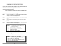
You can easily change the default settings by simply scanning the bar code
options located on the READER SETUP MENU. The READER SETUP MENU is
a laminated sheet of bar codes supplied with this manual.
The basic programming sequence is:
START / CATEGORY / OPTION (0-9) / ON/OFF (or) NUMBER ONLY /
EXIT
Follow the instructions below to change the settings.
Step 1:
Scan the START label at the top left corner of the SETUP MENU.
This puts the reader into the program mode.
Step 2:
Scan one of the CATEGORY labels (i.e. Code 39, UPC, Baud
Rate).
Step 3:
Select the desired option by scanning one of the numeric labels
(0 - 9).
Step 4:
If there is an (ON/OFF) next to the description, scan an ON label to
enable or OFF label to disable the option.
EXAMPLE: To enable the MOD 43 check digit on Code
39, perform the following:
1)
2)
3)
Scan the "CODE 39" category label.
Scan option "2" label to select "MOD 43
CHECK DIGIT" option.
Scan the "ON" label to enable it.
If there is a range of numbers next to the option, then scan one of
the numeric labels (0 -9).
EXAMPLE: To select the OPCC check digit for
Interleaved 2 of 5, perform the following:
1) Scan the "INT. 2 of 5" category label.
2) Scan the "1" label to select the "CHECK DIGIT" option.
3) Scan the "2" label to select OPCC.
25
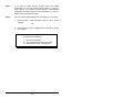
Step 5:
If you want to make another change within the SAME
CATEGORY, you can scan another option number (i.e., return to
Step 3 above). If you want to make a change in a DIFFERENT
CATEGORY you MUST scan the new CATEGORY (i.e., return to
Step 2 above and repeat the steps).
Step 6:
When you have finished making all of the changes, you can either:
1)
2)
SCAN the EXIT
changes
(Save Changes)
label to
save
all the
OR
SCAN the EXIT (Ignore Changes) label to exit without saving
any changes.
NOTE:
You can reset the reader to the default settings
by performing the following:
1) Scan the START label.
2) Scan the RESET ALL DEFAULTS label.
3) Scan the EXIT (Save Changes) label.
26
PROGRAMMING GUIDE
START
The START bar code places the reader into the program mode. After
scanning this label, the reader will emit three short BEEPS to indicate that it is
in the program mode.
EXIT (SAVE CHANGES)
Scan this bar code to EXIT the program mode and save all of the changes.
After scanning this label, the reader will BEEP twice then delay
approximately one second and emit three short BEEPS to indicate that it
accepted the changes.
EXIT (IGNORE CHANGES)
Scan this bar code to EXIT the program mode and DISCARD all of the
current changes. The reader will use the settings that were in effect before
entering the program mode.
RESET ALL DEFAULTS
Scan this bar code to RESET all options to their DEFAULT settings.
NOTE: Defaults are marked with "*".
0-9 BAR CODES
These bar codes are scanned to select various options and enter
programmable data into the reader.
NOTE: Scan option (9) to reset all of the options within the
current CATEGORY back to their defaults.
ON
OFF
If the OPTION has an (ON/OFF) beside the description, scan the ON bar code
to turn ON the current option.
If the OPTION has an (ON/OFF) beside the description, scan the OFF bar
code to turn OFF the current option.
FULL ASCII CHART
The FULL ASCII CHART is located on the back of the READER SETUP
MENU. This chart contains the entire ASCII character set (128
characters). Use this chart to enter PREAMBLE and POSTAMBLE
character strings as well as the RECORD TERMINATOR and
SEPARATOR characters.
ADDITIONAL NOTES:
If the description beside the OPTION contains:
(ON/OFF) Then scan either an ON or OFF label to set the option.
(CHART) Then scan one or more characters from the Full ASCII Chart.
(0-9)
Scan the disired character from the 0-9 labels.
(0.0-9.9) Scan two characters from the 0-9 labels to set the time from 0
to or (0.0-99) 9.9 seconds, or 0 to 99 seconds.
27
CODE 39
0) CODE 39 DECODER
ON*
Enable reading CODE 39 labels.
OFF
1) FULL ASCII
ON
OFF*
Disable reading CODE 39 labels.
Enable the FULL ASCII EXTENSION to CODE 39.
Option #0 above must be set ON.
Disable the FULL ASCII EXTENSION to CODE 39.
This sets the reader to the standard CODE 39 mode.
2) MOD 43 CHECK DIGIT
ON
Enable the MOD 43 CHECK DIGIT for CODE 39.
When this option is enabled, only CODE 39 labels
that contain a valid check digit will be read.
OFF*
Disable the MODE 43 CHECK DIGIT.
verification will not be performed.
Check digit
3) SEND CHECK DIGIT
ON
Transmit the MOD 43 CHECK DIGIT with the bar
code data. Requires option #2 above to be set ON.
OFF*
Do not transmit the MOD 43 CHECK DIGIT.
4) CONCATENATE MODE
ON
Enable CONCATENATE MODE. The concatenate
mode allows the reader to accumulate multiple bar
codes in its buffer, then send them to the computer
just like they were a single bar code. When a
Code 39 label containing a leading space is read,
the reader emits two short beeps and buffers the
data without transmission. This process continues
until a Code 39 label without a leading space is
read or 128 characters are buffered. A Code 39
bar code label that only contains a single or
multiple dashes (minus sign) will clear the buffer.
OFF*
Disable CONCATENATE MODE.
28
UPC
0) UPC DECODER
ON*
Enable reading UPC-A and UPC-E labels.
OFF
Disable reading UPC-A and UPC-E labels.
1) CONVERT UPC-E TO UPC-A
ON
Convert all UPC-E labels to their UPC-A equivalents
before transmission. After conversion, the reader will
follow the UPC-A programming options.
OFF*
No conversions will be performed.
2) CONVERT UPC-A TO EAN-13
ON
Convert all UPC-A labels to an equivalent EAN-13
format by inserting a leading zero. After conversion,
the reader will follow the EAN-13 programming
options.
OFF*
No conversions will be performed.
3) SEND UPC-A NUMBER SYSTEM
ON*
Transmit the UPC-A NUMBER SYSTEM character.
OFF
Do not transmit the UPC-A NUMBER SYSTEM
character.
4) SEND UPC-E NUMBER SYSTEM
ON*
Transmit the UPC-E NUMBER SYSTEM character.
OFF
Do not transmit the UPC-E NUMBER SYSTEM
character.
5) SEND UPC-A CHECK DIGIT
ON*
Transmit the UPC-A CHECK DIGIT character.
OFF
Do not transmit the UPC-A CHECK DIGIT character.
6) SEND UPC-E CHECK DIGIT
ON*
Transmit the UPC-E CHECK DIGIT character.
OFF
Do not transmit the UPC-E CHECK DIGIT character.
29
EAN
0) EAN DECODER
ON*
Enable reading EAN-8 and EAN-13 labels.
OFF
Disable reading EAN-8 and EAN-13 labels.
1) ZERO FILL EAN-8 TO EAN-13
ON
Add five leading zeroes to EAN-8 labels. After
conversion, the reader will follow the EAN-13
programming options.
OFF*
No conversion is performed.
2) SEND EAN-13 COUNTRY CODE
ON*
Transmit the EAN-13 COUNTRY CODE.
OFF
Do not transmit the EAN-13 COUNTRY CODE.
3) SEND EAN-8 COUNTRY CODE
ON*
Transmit the EAN-8 COUNTRY CODE.
OFF
Do not transmit the EAN-8 COUNTRY CODE.
4) SEND EAN-13 CHECK DIGIT
ON*
Transmit the EAN-13 CHECK DIGIT character.
OFF
Do not transmit the EAN-13 CHECK DIGIT
character.
5) SEND EAN-8 CHECK DIGIT
ON*
Transmit the EAN-8 CHECK DIGIT character.
OFF
Do not transmit the EAN-8 CHECK DIGIT character.
6) ISBN CONVERSION
ON
Convert 13 DIGIT BOOKLAND/EAN (978 prefix) to
its corresponding 10 DIGIT ISBN number.
EXAMPLE: BAR CODE DATA
= 9780806957906
ISBN OUTPUT DATA = 0806957905
OFF*
Do not convert Bookland/EAN to an ISBN number.
30
UPC/EAN SUPPLEMENTS
0) SUPPLEMENTS DECODER
ON
Enable reading UPC & EAN supplements.
OFF*
Disable reading UPC & EAN supplements.
1) ALLOW 2 DIGIT
ON*
Enable reading 2 digit supplements. Option 0 above
must be set ON.
OFF
Disable reading 2 digit supplements.
2) ALLOW 5 DIGIT
ON*
Enable reading 5 digit supplements. Option 0 above
must be set ON.
OFF
Disable reading 5 digit supplements.
3) REQUIRE SUPPLEMENTS
Specifies how the reader will handle various supplements.
0)*
UPC/EAN bar codes will be read with or without valid
supplements.
1)
UPC bar codes will not be read unless they are
accompanied by a valid supplement.
2)
EAN bar codes will not be read unless they are
accompanied by a valid supplement.
3)
Bookland EAN bar codes will not be read unless they
are accompanied by a valid supplement.
4)
All UPC/EAN bar codes will not be read unless they
are accompanied by a valid supplement.
4) SEND SEPARATOR SPACE
ON
Insert a space between the standard bar code data
and the supplemental data.
OFF*
No separator space is inserted.
31
INTERLEAVED 2 OF 5
0) I 2 OF 5 DECODER
ON*
Enable reading INTERLEAVED 2 of 5 labels.
OFF
Disable reading INTERLEAVED 2 of 5 labels.
1) CHECK DIGIT: 0=NONE, 1=USS, 2=OPCC
Specifies which type of check digit will be used with INTERLEAVED
2 of 5:
0* = NONE (no check digit required)
1 = UNIFORM SYMBOLOGY SPECIFICATION
(3-1-3 MOD 10)
2 = OPTICAL PRODUCT CODE COUNCIL
(2-1-2 MOD 10)
2) SEND CHECK DIGIT
ON
Transmit the INTERLEAVED 2 of 5 check digit with
the bar code data.
OFF*
The check digit is not transmitted.
3) FIXED LENGTH
ON
Read only FIXED LENGTH INTERLEAVED 2 of 5
bar code labels that match the lengths defined in
options #4 & #5 below. The check digit can be on or
off.
OFF*
Disable FIXED LENGTH mode. Read all
INTERLEAVED 2 of 5 labels without regard to length.
4) SET FIXED LENGTH #1 (02-60)
Sets the first valid FIXED LENGTH for Interleaved 2 of 5.
Scan a two digit value to enter the length. Valid lengths
are 02 to 60 characters. By definition, the length of
Interleaved 2 of 5 labels are an even number of characters.
The default FIXED LENGTH is 6 characters.
5) SET FIXED LENGTH #2 (02-60)
Sets a second valid fixed LENGTH for Interleaved 2 of 5.
Scan a two digit value to enter the length. The default
length is set to 0 characters (i.e. the second FIXED
LENGTH is disabled).
32
CODABAR
0) CODABAR DECODER
ON *
Enable reading CODABAR labels.
OFF
Disable reading CODABAR labels.
1) SEND START/STOP
ON
Transmit the CODABAR start/stop characters.
OFF *
Do not transmit the CODABAR start/stop characters.
2) CLSI FORMATTING
ON
The reader will insert a blank after the 1st, 5th, and
10th characters of a 14-character CODABAR label.
The label length does not include the start and stop
characters.
OFF *
Disable CLSI formatting.
3) CLSI CHECK DIGIT
ON
Enable the CLSI check digit. When this option is
enabled, all fourteen digit numeric bar codes must
contain a valid check digit.
OFF*
Disable the CLSI check digit. Check digit verification will
not be performed.
CODE 128
0) CODE 128 DECODER
ON *
Enable reading Code 128 labels.
OFF
Disable reading Code 128 labels.
1) UCC-128 VERIFICATION
ON
A valid MOD 10 CHECK DIGIT is required on UCCMOD 10 bar codes. (Applies to 20-digit serial
shipping container bar codes.)
OFF *
UCC-MOD 10 bar codes are accepted without valid
MOD 10 CHECK DIGITS.
2) SEND MOD 10 CHECK DIGIT
ON *
Transmit the MOD 10 CHECK DIGIT with the bar
code entry.
OFF
Do not transmit the MOD 10 CHECK DIGIT.
33
CODE 93
0) CODE 93 DECODER
ON*
Enable reading Code 93 labels.
OFF
Disable reading Code 93 labels.
1) CONCATENATE MODE
ON
Enable CONCATENATE MODE. The concatenate
mode allows the reader to concatenate multiple
bar codes in its buffer, then send them to the
computer just like they were a single bar code.
When a Code 93 label with a leading space is
read, the reader emits two short beeps and buffers
the data without transmission. This process
continues until a Code 93 label without a leading
space is read or 128 characters are buffered. A
Code 93 bar code label that only contains a single
or multiple dashes (minus sign) will clear the
buffer.
CODE 11
OFF*
Disable CONCATENATE MODE.
0) CODE 11 DECODER
ON
Enable reading CODE 11 labels.
OFF *
Disable reading CODE 11 labels.
1) TWO CHECK DIGITS REQUIRED
ON
Two valid CHECK DIGITS are required for each
label.
OFF *
One valid CHECK DIGIT is required for each label.
2) SEND FIRST CHECK DIGIT
ON
Transmit the FIRST CHECK DIGIT.
OFF *
Do not transmit the FIRST CHECK DIGIT.
3) SEND SECOND CHECK DIGIT
ON
Transmit the SECOND CHECK DIGIT.
OFF *
Do not transmit the SECOND CHECK DIGIT.
34
MSI/PLESSEY
0) MSI/PLESSEY DECODER
ON
Enable reading MSI/PLESSEY labels.
OFF *
Disable reading MSI/PLESSEY labels.
1) TWO CHECK DIGITS REQUIRED
ON
Two valid CHECK DIGITS are required for each label.
The first check digit is defined by option (2) below.
The second check digit is always MOD 10.
OFF *
One valid CHECK DIGIT is required for each label.
The CHECK DIGIT must be MOD 10.
2) FIRST CHECK DIGIT MOD 11
ON
The FIRST CHECK DIGIT must be MOD 11.
OFF *
The FIRST CHECK DIGIT must be MOD 10.
3) SEND FIRST CHECK DIGIT
ON
Transmit the FIRST CHECK DIGIT.
OFF *
Do not transmit the FIRST CHECK DIGIT.
4) SEND SECOND CHECK DIGIT
ON
Transmit the SECOND CHECK DIGIT.
OFF *
Do not transmit the SECOND CHECK DIGIT.
5) ISBN PLESSEY
ON
Enable reading of Modified Plessey ISBN bar codes.
Only eleven digit ISBN bar codes will be read.
OFF*
Do not read Modified Plessey ISBN bar codes.
35
SERIAL PORT
The RS-232C serial port transmits and receives data from both the host
computer and the terminal. The reader's serial port parameters must
match those of the terminal.
0) DATA TYPE: 0=ASCII 1=PC SCAN CODES
0*
Sets the data format to ASCII characters. Use this
mode with standard ASCII terminals.
1
Sets the data format to PC SCAN CODES. Use this
mode only if you are using a "PC-Terminal" type
terminal. This type of terminal transmits PC SCAN
CODES to the host computer. Some operating
systems that use these types of terminals are: PCMOS, CONCURRENT DOS, etc.
1) DUPLEX MODE: 0=FULL 1=HALF
0*
Selects FULL DUPLEX mode. In FULL DUPLEX, the
reader transmits data out the HOST port only. The
host computer receives the data and echoes it back
to the terminal.
1
Selects HALF DUPLEX mode. In HALF DUPLEX,
the readers transmits data out both the HOST and
TERMINAL ports at the same time.
2) INTERCHARACTER DELAY (00 - 99 msec)
This option specifies the amount of delay to be inserted
after transmitting each character. The delay period is
programmable from 00 to 99 msec. This feature allows the
user to slow the data rate down for host computers that
require more time to process each character.
3) DAISY CHAIN (ON/OFF, ID)
This option specifies the Daisy Chain mode of operation.
ON
Enables Daisy Chain Controller operation. When
enabled, the unit polls and accepts data from each
M2500 that is in the daisy chain.
OFF*
Disables all Daisy Chain operations.
operates as a stand alone unit.
ID
Designates the unique daisy chain ID. Accepts ID
values from the Full ASCII Chart in the range of
"SP" to "DEL" (ASCII 32-127).
36
M2500
4) SEND DAISY CHAIN ID (ON/OFF)
ON
Sends the daisy chain ID at the beginning of data
transmit, when in the daisy chain mode.
OFF*
Does not send daisy chain ID.
5) HOST RESPONSE (ON/OFF)
ON
Unit requires receipt of a Host Response after
each data transmit. When used during daisy chain
mode, the command must be preceeded by the
daisy chain ID.
OFF*
Unit does not require a Host Response.
Valid Host Responses are:
CTRL G (ASCII 7) CTRL R (ASCII 18) CR
(ASCII 13) -
Single Beep.
High/Low warble tone.
Data OK. No action
needed.
6) HOST RESPONSE TIMEOUT (00-99 SEC)
This parameter specifies how long the M2500 will wait for the
host response. If the response timeout is set to zero then the
M2500 will wait indefinitely. If a response is not received
within the timeout period, the M2500 will continue scanning.
The host response delay is programmable from 0-99 seconds.
7) HOST BEEP ENABLE (ON/OFF)
ON
Enables receipt of commands from the Host
Computer. These commands can be sent at any
time.
CTRL G (ASCII 7)
CTRL R (ASCII 18)
OFF*
-
Single Beep.
High/Low warble tone.
Disables Host Commands.
37
BAUD RATE
The baud rate sets the data transmission speed for the serial interface
port on the reader. The readers baud rate must match the terminal.
Select one of the following:
0)
1)
2)
3)
4)
5)
6)*
7)
8)
150
300
600
1200
2400
4800
9600
19,200
38,400
PARITY
Sets the parity for the serial interface data. This setting must match the
terminal. Select one of the following:
0)*
1)
2)
3)
NONE
EVEN
ODD
MARK
DATA BITS
Sets the character length (number of data bits per character) for the
serial interface data. This setting must match the terminal. Select one
of the following:
0)
1)*
7 BITS
8 BITS
38
PREAMBLES
PREAMBLE refers to a user-defined set of characters transmitted at the
beginning of each type of input data. There are two different
preambles. One set for bar code data, and one set for magnetic stripe
data.
0) ENTER BAR CODE PREAMBLE
This set of user-defined characters is transmitted at the
beginning of bar code data. To define this preamble, scan up
to 15 characters from the FULL ASCII section of the MENU
and then scan the "ON" bar code when you are done.
1) ENTER MAG STRIPE PREAMBLE
This set of user-defined characters is transmitted at the
beginning of magnetic stripe data. To define this preamble,
scan up to 15 characters from the FULL ASCII section of the
MENU and then scan the "ON" bar code when you are done.
2) BAR CODE SEND DELAY (0.0 - 9.9 SEC)
This option specifies the amount of delay to occur after the bar
code preamble is transmitted. The delay period is
programmable from 0.0 to 9.9 seconds.
3) MAG SEND DELAY (0.0 - 9.9 SEC)
This option specifies the amount of delay to occur after the
mag stripe preamble is transmitted. The delay period is
programmable from 0.0 to 9.9 seconds.
4) ACTIVE TYPES
Specifies the types of bar codes that use preambles. Select
one of the following:
A
B
C
D
E
F
CODE 39
UPC-A
UPC-E
EAN-13
EAN-8
INTERLEAVED 2 of 5
X* ALL BAR CODES
39
G
H
I
J
K
L
CODABAR
CODE 128
CODE 93
MSI/PLESSEY
CODE 11
ISBN
POSTAMBLES
POSTAMBLE refers to a user-defined set of characters transmitted at
the end of each type of input data. There are two different postambles.
One set for bar code data, and one set for magnetic stripe data.
0) ENTER BAR CODE POSTAMBLE
This set of user-defined characters is transmitted at the end of
bar code data. To define this postamble, scan up to 15
characters from the FULL ASCII section of the MENU and then
scan the "ON" bar code when you are done.
1) ENTER MAG STRIPE POSTAMBLE
This set of user-defined characters is transmitted at the end of
mag stripe code data. To define this postamble, scan up to 15
characters from the FULL ASCII section of the MENU and then
scan the "ON" bar code when you are done.
2) BAR CODE SEND DELAY (0.0 - 9.9 SEC)
This option specifies the amount of delay to occur after the bar
code postamble is transmitted. The delay period is
programmable from 0.0 to 9.9 seconds.
3) MAG SEND DELAY (0.0 - 9.9 SEC)
This option specifies the amount of delay to occur after the
mag stripe postamble is transmitted. The delay period is
programmable from 0.0 to 9.9 seconds.
4) ACTIVE TYPES
Specifies the types of bar codes that can accept appended
postambles. Select one of the following:
A
B
C
D
E
F
CODE 39
UPC-A
UPC-E
EAN-13
EAN-8
INTERLEAVED 2 of 5
X* ALL BAR CODES
40
G
H
I
J
K
L
CODABAR
CODE 128
CODE 93
MSI/PLESSEY
CODE 11
ISBN
TERMINATION CHARACTER
The optional TERMINATION CHARACTER is transmitted at the end of
the data. This option applies to bar code, mag stripe, and serial data.
If a USER DEFINED TERMINATION CHARACTER is desired, select
setting (4) below, then scan a single character from the FULL ASCII
section of the MENU.
0)
1)
2)*
3)
4)
NONE
HORIZONTAL TAB (ASCII 09)
CARRIAGE RETURN (ASCII 13)
CARRIAGE RETURN & LINEFEED
(ASCII 13 & ASCII 10)
USER DEFINED TERMINATION CHARACTER
BEEP LENGTH & TONE
Settings (0-3) set the LENGTH of the BEEP. Settings (4-7) set the
TONE (pitch) of the BEEP. Setting (8), when selected, will override the
other BEEP selections and shut off the BEEP.
LENGTH:
0)
1)*
2)
3)
TONE:
4)
5)
6)*
7)
OFF:
8)
SHORT
MEDIUM SHORT
MEDIUM LONG
LONG
LOW
MEDIUM LOW
MEDIUM HIGH
HIGH
NO BEEP
41
MAG STRIPE OPTIONS #1
0) SEND ACCOUNT NUMBER
(This option valid only if option (3) below is OFF.)
ON *
Transmit the ACCOUNT NUMBER data from the
magnetic card. On major credit cards, the account
number is available on TRACKS 1 & 2.
OFF
Do not transmit the ACCOUNT NUMBER.
1) SEND NAME (TRACK 1 ONLY)
(This option valid only if option (3) below is OFF.)
ON *
Transmit the NAME data from the magnetic card. On
major credit cards, the NAME is available only on
TRACK 1.
OFF
Do not transmit the NAME.
2) SEND EXPIRATION DATE
(This option valid only if option (3) below is OFF.)
ON *
Transmit the EXPIRATION DATE. On major credit
cards, the EXPIRATION DATE is available on
TRACKS 1 & 2.
OFF
Do not transmit the EXPIRATION DATE.
3) SEND ALL TRACK DATA
ON *
Transmit ALL the data from each enabled track. The
data is transmitted as it appears on the card with NO
formatting. However, SEPARATOR CHARACTERS
will be inserted between fields; see options (4) and
(6) for information on SEPARATOR CHARACTERS.
OFF
Disables this option.
NOTE: If this option is ON, it overrides options (0), (1), (2), and (5).
4) ENTER TRACK 1 SEPARATOR CHARACTER
(This option valid only if option (3) is ON.)
The TRACK 1 SEPARATOR CHARACTER, which separates
the Track 1 fields, can be programmed by the user. Scan a
single character from the FULL ASCII section of the MENU.
The default is "^" (ASCII 94).
42
5) FORMAT EXPIRATION DATE MMYY
(This option valid only if option (3) is OFF.)
ON
EXPIRATION DATE format = MMYY
OFF *
EXPIRATION DATE format = YYMM
6) ENTER TRACKS 2 & 3 SEPARATOR CHAR
(This option valid only if option (3) is ON.)
The TRACKS 2 & 3 SEPARATOR CHARACTER, which
separates the fields on tracks 2 and 3, can be programmed by
scanning a single character from the FULL ASCII section of
the MENU. The default is "=" (ASCII 61).
43
MAG STRIPE OPTIONS #2
0) OUTPUT
This option designates which track(s) will be output, and in
what order. (To use a Dual Track decoder with a Single Track
application, select FIRST TRACK (only) or SECOND TRACK
(only)). Select one of the following:
0)
1)
2) *
3)
NOTE:
FIRST TRACK (only)
SECOND TRACK (only)
BOTH (output in order)
BOTH (REVERSE ORDER)
For a dual track (tracks 2&3) mag stripe
reader, FIRST TRACK represents track 2,
and SECOND TRACK represents track 3.
1) REQUIRE TWO TRACKS
ON
Two tracks of mag stripe data must be read for a
"good read" to occur. (Only for use with dual track
readers.)
OFF *
NOTE:
The decoder will accept one (or more) valid tracks as
a "good read".
THIS OPTION MUST BE OFF FOR ALL
SINGLE TRACK READERS. (Optional for dual
track readers.)
2) SEND START & END SENTINELS
(This option valid only if SEND ALL TRACK DATA is ON.)
ON *
The START/END SENTINEL characters for each
enabled track will be transmitted. The characters for
each type of sentinel are listed below:
1)
2)
3)
OFF
Track 1 START SENTINEL =
Tracks 2 & 3 START SENTINEL =
Tracks 1, 2, & 3 END SENTINEL =
"%"
";"
"?"
Do not transmit the START/END SENTINEL
characters.
44
3) BETWEEN TRACKS/FIELDS TERM CHARACTER
The CHARACTER to be output is defined from the
TERMINATION CHARACTER option. The default is a
carriage return (ENTER).
ON
Transmit the TERMINATION CHARACTER between
each track/field which is read. The insertion location
is according to the following:
a) IF the SEND ALL TRACK DATA option is ON,
the character will be inserted between TRACKS.
b) IF the SEND ALL TRACK DATA option is OFF,
the character will be inserted between FIELDS.
OFF *
Do not transmit the BETWEEN TRACKS/FIELDS
TERMINATION CHARACTER.
4) SEND ENDING TERMINATION CHARACTER
The CHARACTER to be output is defined from the
TERMINATION CHARACTER option. The default is a
carriage return (ENTER).
ON *
Transmit the TERMINATION CHARACTER after all
data has been sent.
OFF
Do not transmit the ENDING TERMINATION
CHARACTER.
5) STRIP SPACES
(This option valid only if SEND ALL TRACK DATA is OFF.)
ON *
All spaces will be stripped from the ACCOUNT
NUMBER FIELD, and any leading or trailing spaces
will be stripped from the NAME FIELD.
OFF
Do not strip any spaces from the mag stripe data.
45
BAR CODE EDIT
This option allows editing bar codes before transmittal.
0) BAR CODE EDITING
(Must be ON for any of the editing options below to be valid.)
ON
Enable Bar Code Editing.
OFF *
Disable Bar Code Editing.
1) ENTER # OF LEADING CHAR TO STRIP (0-9)
(Option (0) above must be ON.) Refers to the number (0-9) of
bar code characters to be stripped, i.e., removed, from the
beginning of the data entry.
2) ENTER # OF TRAILING CHAR TO STRIP (0-9)
(Option (0) above must be ON.) Refers to the number (0-9) of
bar code characters to be stripped, i.e., removed, from the end
of the data entry.
NOTE:
If the total number of strip characters (both
Leading and Trailing) is greater than the
number of characters of the bar code, no
characters will be stripped.
3) ENTER BAR CODE TYPE TO EDIT
(Option (0) above must be ON.) Refers to the type of bar
codes for which editing can be enabled. Select one of the
following:
A
B
C
D
E
F
CODE 39
UPC-A
UPC-E
EAN-13
EAN-8
INTERLEAVED 2 of 5
G
H
I
J
K
X*
CODABAR
CODE 128
CODE 93
MSI/PLESSEY
CODE 11
ALL BAR CODES
4) STRIP LEADING & TRAILING SPACES
(Option (0) above must be ON.)
ON
Any LEADING & TRAILING SPACES will be stripped
from the data.
OFF *
No spaces will be stripped.
46
OPTIONS #1
0) SEND BAR CODE TYPE ID
ON
Transmit the bar code identifier character at the
beginning of the bar code data. There is one space
between the ID character and the bar code data. The
identifier characters are defined below:
A
B
C
D
E
F
OFF *
CODE 39
UPC-A
UPC-E
EAN-13
EAN-8
INTERLEAVED 2 of 5
G
H
I
J
K
CODABAR
CODE 128
CODE 93
MSI/PLESSEY
CODE 11
Do not transmit BAR CODE TYPE ID.
1) DUPLICATE READS ALLOWED
ON *
Enable reading the same bar code multiple times.
OFF
Disable reading the same bar code twice in a row.
2) LASER / CCD TIMEOUT (0 - 9)
If the LASER or CCD has not read a bar code within the
designated time period, the device will be turned off. Select
from 0 to 9 seconds. The default is 1 second.
CAUTION: IF THE ABOVE OPTION IS SET AT ZERO (0)
SECONDS, IT WILL OVERRIDE THIS SAFETY
FEATURE.
3) LASER / CCD TRIGGER SHUTOFF
ON *
Releasing the trigger will turn off the LASER or CCD.
OFF
NOTE:
The LASER or CCD will continue to run until a
successful read or until the timeout period (from
option (2), LASER/CCD TIMEOUT) lapses.
To use "Blink Mode" with a CCD or laser, set
this option OFF, and set option (4), LASER/CCD
CONTINUOUS RUN, ON. (Note that "Blink
Mode" will not operate properly for lasers which
employ thermal shut-down.)
47
4) LASER / CCD CONTINUOUS RUN
ON
The LASER or CCD runs continuously as long as the
trigger is pulled. The scanner will not be affected by
the LASER/CCD TIMEOUT and will not shut off after
a "good read".
OFF *
The LASER or CCD runs only when the trigger is
pulled. (The LASER/CCD TIMEOUT option remains
in effect.)
5) CONTINUOUS RUN READ DELAY (0.0 - 9.9 SEC)
(Valid only if option (4) above is ON.) This option sets the
DELAY period between successive reads of the same bar
code. This allows the removal of the bar code from the
scan field without multiple reads. The default setting is 1.0
second. (To select a value, for example, 2.0, scan the "2"
label, then the "0" label.)
6) BAR CODE FUNCTION KEYS
ON
Applies to BAR CODE data, preambles,
postambles, and user defined termination
characters. FUNCTION KEYS F1 through F10 will
be transmitted in place of the ASCII characters
"DC1" (11H) through "SUB" (1AH).
The
FUNCTION KEY values are listed in the Full ASCII
Chart on back of the MENU, and in Appendix A.
OFF *
Disable FUNCTION KEYS.
(Standard ASCII characters are transmitted.)
NOTE: This option is applicable only if the "TRANSMIT
DATATYPE = PC SCAN CODES" or if you are
using SOFTCOM keyboard emulation software.
7) KEYBOARD CAPS LOCK STATUS
ON *
Scan ON to indicate that the keyboard's CAPS
LOCK is turned ON. The result is lower case
Alpha characters being output as Shifted
characters.
OFF
Scan OFF to indicate that the keyboard's CAPS
LOCK is turned OFF. The result is upper case
Alpha characters being output as Shifted
characters.
NOTE:
This option is applicable only if the "TRANSMIT
DATATYPE = PC SCAN CODES" or if you are
using SOFTCOM keyboard emulation software.
48
OPTIONS #2
0) BAR CODE SPECIAL KEYS
This option applies only to BAR CODE data, preambles,
postambles, and user defined termination characters.
ON
SPECIAL KEY characters will be transmitted in place
of a specific set of ASCII characters. The SPECIAL
KEYS are listed in the Full ASCII Chart provided on
back of the SETUP MENU and in Appendix A.
OFF *
Disable SPECIAL KEYS. (Standard ASCII Characters
are transmitted.)
EXAMPLE: With SPECIAL KEYS ON, the bar code
character "STX" will be transmitted as a right
arrow, having the effect of pressing the " "
key at the keyboard.
NOTE:
This option is applicable only if the "TRANSMIT
DATA TYPE = PC SCAN CODES" or if you are
using SOFTCOM keyboard emulation software.
1) KEYBOARD NUM LOCK STATUS
ON
Scan ON to indicate that the keyboard's NUM LOCK
is turned ON.
OFF *
Scan OFF to indicate that the keyboard's NUM LOCK
is turned OFF.
NOTE: This option is applicable only if the "TRANSMIT
DATA TYPE = PC SCAN CODES" or if you are
using SOFTCOM keyboard emulation software.
49
2) MAG STRIPE SPECIAL / FUNCTION KEYS
This option applies to MAG STRIPE data, preambles,
postambles, and user-defined termination characters.
ON
SPECIAL KEYS and FUNCTION KEYS will be
transmitted in place of a specific set of ASCII
characters. The SPECIAL and FUNCTION KEY
values are listed in the Full ASCII Chart provided on
back of the SETUP MENU and in Appendix A.
OFF *
Disable SPECIAL / FUNCTION KEYS.
(Standard ASCII characters are transmitted.)
NOTE:
This option is applicable only if the "TRANSMIT
DATA TYPE = PC SCAN CODES" or if you are
using SOFTCOM keyboard emulation software.
3) TERM CHAR OVERRIDE
ON
If any control character or special character (ie.,
function key, arrow key, etc...) is embedded in the bar
code data, the TERMINATION CHARACTER, the
PREAMBLE, and the POSTAMBLE will not be
transmitted.
OFF * The TERMINATION CHARACTER, the PREAMBLE,
and the POSTAMBLE will be transmitted with all bar
code data.
DIAGNOSTICS
This option executes a self-test program which performs the following
tests on the reader:
*
*
*
*
*
*
EPROM Version Number
Internal and External Ram Test
EPROM Checksum Test
EEPROM Test
Character Set Test
Buzzer Test
The above tests are performed and their status is displayed on the
terminal.
NOTE: Exit your application program and return to the
operating system before enabling this test.
50
CLONING SETUP INFORMATION
When multiple readers are to be setup in the same configuration, it is advantageous
to setup the first reader, and clone (copy) that setup to all the other units. The setup
information can be (1), stored on a computer for cloning from computer to reader,
or (2), cloned directly from one reader to another. These methods are described
below:
CLONING FROM COMPUTER TO READER
BEFORE YOU START, HAVE THE FOLLOWING EQUIPMENT READY:
-
-
A PC CLONE CABLE (with a 9 pin plug (male) and a 25 pin socket
(female)).
A communication software package must be installed on your
computer, and it must have the following configuration settings:
BAUD RATE: must match the reader's setting
DATA BITS:
8 bits
The configured reader, which is to send the clone information, must
have the following configuration setting:
DATA BITS:
8 bits (the default setting)
NOTE: If the clone information has already been sent to your
computer, start at step 10.
Step 1:
Start with the configured reader (denoted as the "SOURCE"
reader) connected to the computer's serial port..
Step 2:
Plug the 9 pin end of the PC CLONE CABLE into the SOURCE
reader's connector labeled "HOST", located on the rear panel of
the reader.
Step 3:
Scan the START bar code on the READER SETUP MENU.
Step 4:
Plug the other end of the PC CLONE CABLE (the 25 pin female)
into the computer's RS-232 serial port.
Step 5:
At the computer, run your communications program and put it into
RECEIVE mode.
51
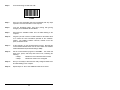
Step 6:
Scan the following "CLONE" bar code:
CLONE
Step 7:
Once the clone information has been transmitted, take any steps
required to save the information on the computer.
Step 8:
From the SOURCE reader, scan EXIT (saving OR ignoring
changes) on the READER SETUP MENU.
Step 9:
Disconnect the SOURCE reader from all cables leading to the
computer.
Step 10:
Plug the 9 pin end of the PC CLONE CABLE into the reader which
is to receive the clone information (denoted as the "TARGET"
reader). The TARGET reader's connector, located on the rear
panel, is labeled "HOST".
Step 11:
At the computer, run the communications program. Note that the
communications BAUD RATE must be set to match the TARGET
reader's BAUD RATE (the default setting is 9600).
Step 12:
Set the communications program to TRANSMIT. The reader will
beep twice, pause, and beep three times more, indicating the
following:
2 beeps:
indicate the clone information was received
3 beeps:
indicate the reader is now configured
Step 13:
Now you are ready to disconnect the newly configured reader from
all cables leading to the computer.
Step 14:
Repeat steps 10 -14 for each additional reader to be cloned.
52
CLONING FROM READER TO READER
BEFORE YOU START, HAVE THE FOLLOWING EQUIPMENT READY:
-
A READER CLONE CABLE (with two 9 pin male plugs).
The two readers.
The reader which is to receive the clone information must have
the following configuration settings:
BAUD RATE: must match the configured reader's setting
DATA BITS:
8 bits (the default setting)
Step 1:
Plug one end of the READER CLONE CABLE into the configured
reader (denoted as the "SOURCE" reader). The SOURCE's
connector, located on the rear panel of the reader, is labeled
"HOST".
Step 2:
Plug the other end of the READER CLONE CABLE into the reader
which is to receive the clone information; this reader is denoted as
the "TARGET". The TARGET's connector, located on the rear
panel of the reader, is also labeled "HOST".
Step 3:
From the "SOURCE" reader, scan the START bar code on the
READER SETUP MENU.
Step 4:
Still at the "SOURCE" reader, scan the following "CLONE"
bar code:
CLONE
Step 5:
The "TARGET" reader will beep twice, pause, and beep three
times more, indicating it has received the clone information and is
now configured.
Step 6:
Disconnect the CLONE CABLE from the newly configured
TARGET reader.
Step 7:
For each additional reader to be cloned, connect a TARGET reader
to the source reader and repeat steps 2 through 6.
Step 8:
When cloning is complete, go to the SOURCE reader and scan
EXIT (saving OR ignoring changes) on the READER SETUP
MENU.
Step 9:
Next, disconnect the CLONE CABLE from the SOURCE reader.
53
SPECIFICATIONS
BAR CODES SUPPORTED
Auto-discriminates between all of the following codes:
Code 3 of 9 (Code 39)
Extended Code 3 of 9 (Full ASCII)
Interleaved 2 of 5 (Variable and Fixed Length, Check Digit)
UPC-A (Including 2 and 5 Character Supplements)
UPC-E(0), UPC-E(1)
EAN/JAN (Including 2 and 5 Character Supplements)
Codabar
Code 128
Code 93
Code 11
MSI/Plessey
INPUT DEVICES SUPPORTED
Lasers (Helium-Neon, Visible Laser Diode, Infrared)
CCD Scanners
Wands (Visible and Infrared)
Slot Readers (Or Badge Readers)
Magnetic Stripe Readers (Single or Dual Track)
USER PROGRAMMABLE FEATURES
All features are easily programmed with a bar code menu:
Bar Code Selection:
Preambles/Postambles:
Enable/Disable
Bar Code (15 Chars Max)
Length
Mag Stripe (15 Chars Max)
Check Digit
Transmit Delay
Start/Stop Transmit
Beep Tone and Length
Mag Stripe Data Format
Laser Configuration:
Laser Time-Out
Trigger Function
Continuous Mode
Inter-Character Delay
RS-232 SERIAL PORT
Baud Rates: 150, 300, 600, 1200, 2400, 4800, 9600, 19.2K, 38.4K
Parity: NONE, ODD, EVEN, MARK
Data Bits: 7 or 8
Signals: Transmit Data, Receive Data, Signal Ground, DTR, RTS, CTS, DSR, DCD
INDICATORS
Audio "BEEP" Indicates Successful Read
A Red/Green LED Indicates Status of Reader
POWER REQUIREMENTS
Power Consumption = 0.5 Watts. (12V Laser Requires 12V Regulated Supply)
CONNECTORS
Laser Input: 9 Pin "D" Style
Wand Input: 5 Pin DIN Style
Mag Stripe Input: 8 Pin DIN Style
RS-232 Interface: 25 Pin "D" Style
External Power Input: 2.5 mm Barrel
Connector
ENVIRONMENTAL
Operating Temperature: 0o to +50 o C
Storage Temperature: -30o to +70 o C
Relative Humidity:
5% to 95%
(Non-Condensing)
PHYSICAL SPECIFICATIONS
Weight: 14
oz
Width: 5 1/8 in
Length: 5 1/4 oz
Height: 1 1/2 in
54
SIGNAL DEFINITIONS
WAND/MAG STRIPE INTERFACE
PIN
SIGNAL
1
+5V
2
DATA (____
DATA - MAG STRIPE)
3
GROUND
_____
4
CLOCK (MAG STRIPE)
___________
5
CARD
PRESENT (MAG STRIPE)
5
1
4
2
3
DUAL MAG STRIPE INTERFACE
PIN
SIGNAL
1
+5V
____ TRACK 2
2
DATA,
_____
3
CLOCK, TRACK 2
4
GROUND
____
5
DATA, TRACK 1
_____
6
CLOCK, TRACK 1
___________
7
CARD PRESENT
8
GROUND
8
7
1
6
2
5
LASER INTERFACE
PIN
SIGNAL
1
SYNC
2
DATA
3
DECODE LED
4
NO CONNECTION
5
TRIGGER
6
HEAD ENABLE
7
GROUND
8
SHIELD GROUND
9
LASER POWER
1
RS-232C HOST /TERMINAL INTERFACE
PIN
SIGNAL
1
FRAME GROUND
2
*TRANSMIT DATA
3
*RECEIVE DATA
4
REQUEST TO SEND
5
CLEAR TO SEND
6
DATA SET READY
7
SIGNAL GROUND
8
DATA CARRIER DETECT
9 (20) DATA TERMINAL READY
(pin 20 on the 25 pin cable assemblies)
3
4
2
3
4
5
6
7
8
9
5
4
3
2
9
8
7
1
6
* Pin 2 from HOST is connected to Pin 3 of TERMINAL while
Pin 3 of HOST is connected to Pin 2 of TERMINAL.
EXTERNAL POWER SUPPLY INTERFACE
CONNECTOR: FEMALE BARREL 2.5mm x 5.5mm (9 - 12 VDC, center positive)
-
+
55
APPENDIX A - FUNCTION & SPECIAL KEYS
With FUNCTION KEYS enabled, the decoder can accept a given ASCII
character and transmit a corresponding FUNCTION KEY to the computer. The
ASCII characters and values are listed in the table below.
ASCII CHARACTERS
FUNCTION KEYS
ASCII VALUES
DC1
F1
17
DC2
F2
18
DC3
F3
19
F4
20
DC4
NAK
F5
21
SYN
F6
22
26
ETB
F7
23
CAN
F8
24
EM
F9
25
SUB
F10
26
SPECIAL KEYS
With SPECIAL KEYS enabled, the decoder can accept a given ASCII character
and transmit a corresponding SPECIAL KEY to the computer. The ASCII
characters and values are listed in the table below.
ASCII CHARACTERS
SPECIAL KEYS
ASCII VALUES
SOH
(Left Arrow)
1
STX
(Right Arrow)
2
ETX
(Up Arrow)
3
EOT
(Down Arrow)
4
ENQ
HOME
5
ACK
END
6
BEL
DELETE
7
VT
PAGE UP
11
FF
PAGE DOWN
12
SO
SHIFT ON
14
SI
SHIFT OFF
15
DLE
INS
16
FS
CTRL ON
28
GS
CTRL OFF
29
RS
ALT ON
30
US
ALT OFF
31
A-1
APPENDIX B - EXTERNAL POWER SUPPLY
REQUIREMENTS
The MODEL 2500 can support both 12V and 5V LASERS (and CCD scanners).
The power source for the "LASER" connector on the front panel of the reader is
determined by a jumper located inside the enclosure.
When the jumper is set to the 12V or EXTERNAL position, 12V power is taken
directly from the external power supply. In this configuration an external 12V
regulated power supply MUST be connected to the reader.
When the jumper is set to the 5V or INTERNAL position, 5V power is supplied to
the laser interface.
The following table lists various configuration requirements:
INPUT
DEVICE
LASER
LASER
CCD
POWER
REQUIREMENT
12V
5V
5V
JUMPER
POSITION
EXTERNAL
INTERNAL
INTERNAL
NOTE: The reader is shipped from the factory with the jumper set to
the INTERNAL position. This will supply 5V to the laser.
B-1
APPENDIX C - CODE 39 SPECIFICATIONS
Code 39 is a variable length alphanumeric code. Each character is made up of
nine elements, five bars and four spaces. Three of the elements are wide and
six are narrow. Code 39 is a popular choice for applications because:
-
it is easy to print with low cost dot matrix printers
large character set (A-Z, 0-9, 7 special characters)
code can be extended to include the entire 128 ASCII character set
variable length
0123456789
ABCDE12345
CHARACTERISTICS:
Character Set: 26 uppercase letters (A - Z)
10 digits (0 - 9)
7 special characters (SPACE -.$/+%)
Symbol Length: Variable
Check Digit: Optional
Bi-directional Decoding: Yes
Maximum Density: 9.8 char./inch
(using .0075 inch narrow element)
C-1
CODE 39 CHARACTER SET:
An optional check character can be used for applications requiring higher levels
of data security. When used, the check character immediately follows the last
data character. The check digit is calculated as follows:
1.
Each data character is assigned a numerical value as shown in the
following table:
CHAR
VALUE
CHAR
VALUE
CHAR
VALUE
0
1
2
3
4
5
6
7
8
9
A
B
C
D
E
0
1
2
3
4
5
6
7
8
9
10
11
12
13
14
F
G
H
I
J
K
L
M
N
O
P
Q
R
S
T
15
16
17
18
19
20
21
22
23
24
25
26
27
28
29
U
V
W
X
Y
Z
.
SPACE
$
/
+
%
30
31
32
33
34
35
36
37
38
39
40
41
42
C-2
2.
Sum all of the numerical values for each data character in the bar code.
3.
Divide this sum by 43.
4.
The remainder is the numerical value for the check digit. Use the table in
step 1 to look-up the corresponding character.
EXAMPLE: Sample Code 39 data = A394T
1.
2.
3.
4.
Use the table to lookup the numerical value for each character.
10 + 3 + 9 + 4 + 29 = 55
55 / 43 = 1 remainder 12
Check digit numerical value = 12
The check digit = C.
Bar code with check digit = A394TC
C-3
APPENDIX D - FULL ASCII EXTENSION TO CODE 39
The FULL ASCII EXTENSION expands standard CODE 39 to include the entire
128 ASCII character set. This is accomplished by pairing standard CODE 39
characters. The $, +, /, and % characters are paired as shown in the following
table:
ASCII
CODE
ASCII
CODE
ASCII
CODE
ASCII
CODE
NUL
SOH
STX
ETX
EOT
ENQ
ACK
BEL
BS
HT
LF
VT
FF
CR
SO
SI
DLE
DC1
DC2
DC3
DC4
NAK
SYN
ETB
CAN
EM
SUB
ESC
FS
GS
RS
US
SP
%U
$A
$B
$C
$D
$E
$F
$G
$H
$I
$J
$K
$L
$M
$N
$O
$P
$Q
$R
$S
$T
$U
$V
$W
$X
$Y
$Z
%A
%B
%C
%D
%E
SPACE
!
"
#
$
%
&
'
(
)
*
+
,
.
/
0
1
2
3
4
5
6
7
8
9
:
;
<
=
>
?
@
/A
/B
/C
/D
/E
/F
/G
/H
/I
/J
/K
/L
.
/O
0 or /P
1 or /Q
2 or /R
3 or /S
4 or /T
5 or /U
6 or /V
7 or /W
8 or /X
9 or /Y
/Z
%F
%G
%H
%I
%J
%V
A
B
C
D
E
F
G
H
I
J
K
L
M
N
O
P
Q
R
S
T
U
V
W
X
Y
Z
[
\
]
^
_
`
A
B
C
D
E
F
G
H
I
J
K
L
M
N
O
P
Q
R
S
T
U
V
W
X
Y
Z
%K
%L
%M
%N
%O
%W
a
b
c
d
e
f
g
h
i
j
k
l
m
n
o
p
q
r
s
t
u
v
w
x
y
z
{
¦
}
~
DEL
+A
+B
+C
+D
+E
+F
+G
+H
+I
+J
+K
+L
+M
+N
+O
+P
+Q
+R
+S
+T
+U
+V
+W
+X
+Y
+Z
%P
%Q
%R
%S
%T,%X,
%Y or
%Z
D- 1
APPENDIX E - UPC SPECIFICATIONS
The Universal Product Code (UPC) symbols can be found on almost all retail
products today. The UPC coding system was designed to uniquely identify a
product and its manufacturer.
UPC VERSION A
UPC-A is a fixed length (12 digits) numeric only code with the following features:
0
5
12345 67890
Number System
Character
5-Digit
Product Code
5-Digit
Manufacturer
Number
Check Digit
UPC-A BAR CODE
The NUMBER SYSTEM CHARACTER indicates the type of product the symbol is
identifying:
0,7
2
3
4
5
Regular UPC codes with numbers assigned by the Uniform Code
Council (see appendix on bar code sources).
Random-weight items such as meat and produce.
National Drug Code and National Health Related Items Code.
For in-store marking of non-food items.
Reserved for coupons.
1,6,8,9 Reserved for future use.
E-1
The last digit in UPC bar codes is a MODULO 10 CHECK DIGIT. It is calculated in
the following manner:
1.
From right to left, sum the digits in the odd positions.
2.
Multiply this sum by 3.
3.
From right to left, sum the digits in the even positions.
4.
Add this sum to the product of step 2.
5.
The modulo-10 check digit is the smallest number, which when
added to the sum of Step 4 produces a multiple of 10.
EXAMPLE:
1.
2.
3.
4.
5.
UPC bar code = 01234567890C where C is the
CHECK DIGIT.
Sum 0 + 8 + 6 + 4 + 2 + 0 = 20
Multiply 20 x 3 = 60
Sum 9 + 7 + 5 + 3 + 1 = 25
Sum 60 + 25 = 85
85 + 5 = 90 (check digit = 5)
Therefore: UPC bar code - 012345678905
UPC VERSION E
UPC Version E is a six digit variation of the UPC symbology. The last digit indicates
the type of compression used. Because of this data compression process, the
version E symbol is often referred to as a zero-suppressed symbol.
173559 8
E-2
The following table illustrates the expansion process for converting UPC-E to its
UPC-A equivalent:
Version E
Number
Insertion
Digits
Insertion
Location
Resultant
Version A
XXXXX0
XXXXX1
XXXXX2
XXXXX3
XXXXX4
XXXXX5
XXXXX6
XXXXX7
XXXXX8
XXXXX9
00000
10000
20000
00000
00000
0000
0000
0000
0000
0000
Position 3
Position 3
Position 3
Position 4
Position 5
Position 6
Position 6
Position 6
Position 6
Position 6
XX00000XXX
XX10000XXX
XX20000XXX
XXX00000XX
XXXX00000X
XXXXX00005
XXXXX00006
XXXXX00007
XXXXX00008
XXXXX00009
173559 8
0
VERSION E
17355 00009
8
VERSION A EQUIVALENT
UPC/EAN SUPPLEMENTS
UPC and EAN bar codes can contain supplements that provide two or five digits of
additional information. The supplements are located to the right of standard UPC/
EAN labels. The reader can be programmed to either read or ignore the supplements.
10
0
12345
0
12345 67890
01234 56789
E-3
APPENDIX F - EAN SPECIFICATIONS
The European Article Numbering system (EAN) is a superset of UPC. EAN has two
versions: EAN-13 (13 digits) and EAN-8 (8 digits).
5 012345 678900
5012 3452
EAN 13
EAN 8
Country codes 00, 01, 03, 04, and 06 - 09 are assigned to the U.S. for compatibility
with UPC.
F-1
APPENDIX G - INTERLEAVED 2 of 5 SPECIFICATIONS
The Interleaved 2 of 5 bar code symbology is a numeric code (0 - 9) which has
different start and stop characters. The name Interleaved 2 of 5 is derived from the
fact that two characters are paired together using the bars to represent the first
character and spaces to represent the second. Each character has two wide
elements and three narrow elements.
CHARACTERISTICS:
Character Set:
Symbol Length:
Check Digit:
Bi-directional Decoding:
Maximum Density:
Numeric only (0 - 9)
Variable (must be an even number of digits)
Optional
Yes
18 char./inch
(using .0075 inch narrow element)
CHARACTER SET:
The following table illustrates the data patterns. A "1" represents a wide bar or space
and a "0" represents a narrow bar or space.
CHARACTER
PATTERN
0
1
2
3
4
5
6
7
8
9
start
stop
00110
10001
01001
11000
00101
10100
01100
00011
10010
01010
0000
100
0123456789
G-1
OPTIONAL CHECK DIGIT:
Interleaved 2 of 5 may contain an optional check digit. The reader supports two
types of check digits:
1.
2.
Uniform Symbology Specification (USS) - calculated as modulo 10 check
digit based on 3-1-3 weightings.
Optical Product Code Council (OPCC) - calculated as modulo 10 check digit
based on 2-1-2 weightings.
USS CHECK DIGIT CALCULATION:
1.
2.
3.
4.
5.
From right to left, sum the digits in the odd positions.
Multiply this sum by 3.
From right to left, sum the digits in the even positions.
Add this sum to the product of step 2.
The modulo-10 check digit is the smallest number which when
added to the sum of Step 4 produces a multiple of 10.
EXAMPLE: USS check digit. Sample bar code data: 513827
1. Sum 7 + 8 + 1 = 16
2. Multiply 16 x 3 = 48
3. Sum 2 + 3 + 5 = 10
4. Sum 48 + 10 = 58
5. 58 + 2 = 60 (check digit = 2)
Therefore: Data + check digit = 5138272
NOTE: A leading zero will be required to make it an even
number of characters. The resulting bar code will be:
05138272
OPCC CHECK DIGIT CALCULATION:
1.
2.
3.
4.
From right to left, assign every digit a weighting factor from the
sequence: 2,1,2,1,2,1,2,1,...
Multiply each digit by its weighting factor.
Sum the products in step 2, treating two digit products as the sum
of the individual digits.
The check digit is the smallest number which when added to the
sum of step 3 produces a multiple of 10.
EXAMPLE:
1.
2.
3.
4.
OPCC check digit
Sample bar code data: 020489713
Assign weighting factors: 020489713 212121212
Calculate the products: 0 2 0 4 16 9 14 1 6
Sum the products: 0+2+0+4+1+6+9+1+4+1+6 = 34
34 + 6 = 40 (check digit = 6)
Therefore: Data + check digit = 0204897136
G-2
APPENDIX H - CODABAR SPECIFICATIONS
The Codabar bar code symbology is a numeric code (0 - 9) that also contains six
special characters and four start/stop characters. The start/stop characters may or
may not be transmitted. Characters are constructed of four bars and three spaces.
Codabar is commonly used in libraries, blood banks, cotton industry, and the
transportation industry.
CHARACTERISTICS:
Character Set:
Symbol Length:
Check Digit:
Bi-directional Decoding:
Maximum Density:
10 digits (0 - 9)
6 special characters (- $ : / . +)
4 stop/start characters (a b c d)
Variable
Optional
Yes
12.8 char./inch
(using .0075 inch narrow element)
CHARACTER SET:
The following table illustrates the data patterns. A "1" represents a wide bar or
space and a "0" represents a narrow bar or space.
CHARACTER
PATTERN
0
1
2
3
4
5
6
7
8
9
$
:
/
.
+
a
b
c
d
0000011
0000110
0001001
1100000
0010010
1000010
0100001
0100100
0110000
1001000
0001100
0011000
1000101
1010001
1010100
0010101
0011010
0101001
0001011
0001110
A123456B
H-1
APPENDIX I - CODE 128 SPECIFICATIONS
The CODE 128 symbology is a variable length alphanumeric code containing the full
128 ASCII character set. Each character is made up of 11 modules containing three
bars and three spaces. Bars and spaces can be from 1 to 4 modules wide. Three
different start characters are used to select one of three character sets. Code 128
is the bar code of choice for new applications.
CHARACTERISTICS:
Character Set:
Symbol Length:
Check Character:
Bi-directional Decoding:
Maximum Density:
All 128 ASCII characters
4 function characters
4 code set selection characters
3 start/stop characters
Variable
1
Yes
12.1 alphanumeric char./inch
24.2 numeric digits/inch
(using .0075 inch module element)
0123456789
ABCD123
UCC-128 MOD 10 SERIAL SHIPPING CONTAINER CODE:
FORMAT:
STARTC
FNC1
0000012345555555555
(1)
(2)
(3)
8
C
(4) (5)
STOP
(6)
1. Start Code "C"4. MOD 10 Check Digit
2. FNC1 Character
5. MOD 103 Check Digit
3. 19 Digits
6. Stop Code
00000123455555555558
I-1
CHARACTER SET:
The following table contains the character set for Code 128 subsets A, B, and C:
CODE 128 (USD-6)
VALUE
CODE
A
CODE
B
CODE
C
B
S
0
1
2
3
4
5
6
7
8
9
10
11
12
13
14
15
16
17
18
19
20
21
22
23
24
25
26
27
28
29
30
31
32
33
34
35
36
37
38
39
40
41
42
43
44
45
SP
!
"
#
$
%
&
'
(
)
*
+
,
.
/
0
1
2
3
4
5
6
7
8
9
:
;
<
=
>
?
@
A
B
C
D
E
F
G
H
I
J
K
L
M
SP
!
"
#
$
%
&
'
(
)
*
+
,
.
/
0
1
2
3
4
5
6
7
8
9
:
;
<
=
>
?
@
A
B
C
D
E
F
G
H
I
J
K
L
M
00
01
02
03
04
05
06
07
08
09
10
11
12
13
14
15
16
17
18
19
20
21
22
23
24
25
26
27
28
29
30
31
32
33
34
35
36
37
38
39
40
41
42
43
44
45
2
2
2
1
1
1
1
1
1
2
2
2
1
1
1
1
1
1
2
2
2
2
2
3
3
3
3
3
3
3
2
2
2
1
1
1
1
1
1
2
2
2
1
1
1
1
1
2
2
2
2
3
2
2
3
2
2
3
1
2
2
1
2
2
2
2
2
1
2
1
1
2
2
1
2
2
1
1
3
1
3
3
1
3
3
1
3
3
1
1
3
1
I-2
BAR PATTERN
B
S
B
2
2
2
1
1
1
2
2
2
1
1
1
2
2
2
3
3
3
3
1
1
3
3
2
1
1
1
2
2
2
2
2
2
1
1
1
2
2
2
1
1
1
2
2
2
3
2
1
2
2
3
2
2
3
2
2
3
2
2
1
2
2
1
2
2
1
2
2
1
1
2
1
2
2
1
2
1
3
1
3
1
3
3
1
3
3
1
3
1
3
1
1
2
2
2
2
2
2
1
1
1
1
1
1
3
3
3
2
2
2
1
3
3
1
1
3
2
2
2
1
1
1
2
2
2
2
2
2
1
1
1
1
1
1
3
3
3
2
S
2
2
1
3
2
2
3
2
2
3
2
2
2
2
1
2
2
1
1
2
1
2
2
1
2
2
1
2
2
1
3
1
1
3
3
1
3
3
1
3
3
1
3
1
1
3
CODE 128 (USD-6)
VALUE
CODE
A
CODE
B
CODE
C
B
S
46
47
48
49
50
51
52
53
54
55
56
57
58
59
60
61
62
63
64
65
66
67
68
69
70
71
72
73
74
75
76
77
78
79
80
81
82
83
84
85
86
87
88
89
90
N
O
P
Q
R
S
T
U
V
W
X
Y
Z
[
\
]
^
_
NUL
SOH
STX
ETX
EOT
ENQ
ACK
BEL
BS
HT
LF
VT
FF
CR
SO
SI
DLE
DC1
DC2
DC3
DC4
NAK
SYN
ETB
CAN
EM
SUB
N
O
P
Q
R
S
T
U
V
W
X
Y
Z
[
\
]
^
_
`
a
b
c
d
e
f
g
h
i
j
k
l
m
n
o
p
q
r
s
t
u
v
w
x
y
z
46
47
48
49
50
51
52
53
54
55
56
57
58
59
60
61
62
63
64
65
66
67
68
69
70
71
72
73
74
75
76
77
78
79
80
81
82
83
84
85
86
87
88
89
90
1
1
3
2
2
2
2
2
3
3
3
3
3
3
3
2
4
1
1
1
1
1
1
1
1
1
1
1
1
2
2
4
2
1
1
1
1
1
1
1
4
4
4
2
2
1
3
1
1
3
1
1
1
1
1
3
1
1
3
1
2
3
1
1
2
2
4
4
1
1
2
2
4
4
4
2
1
4
3
1
2
2
1
2
2
1
2
2
1
1
I-3
BAR PATTERN
B
S
B
3
3
3
1
1
3
3
3
1
1
1
2
2
2
4
1
1
1
1
1
1
1
1
2
2
2
2
2
2
1
1
3
1
4
1
1
1
4
4
4
1
1
1
2
4
3
1
1
3
1
1
3
1
1
3
1
1
3
1
1
4
1
2
4
1
4
1
2
2
4
1
4
1
2
2
1
1
1
1
2
1
2
2
1
2
2
1
2
1
1
2
2
2
3
3
1
1
3
2
2
2
1
1
1
1
1
1
2
2
2
2
2
2
1
1
1
1
1
1
1
1
1
1
1
4
4
4
1
1
1
1
1
1
4
2
S
1
1
1
1
1
3
1
1
3
1
1
3
1
1
1
1
1
4
2
4
1
2
1
4
2
4
1
2
1
1
4
1
2
1
2
2
1
2
2
1
2
2
1
1
1
CODE 128 (USD-6)
VALUE
CODE
A
CODE
B
CODE
C
B
S
91
92
93
94
95
96
97
98
99
100
101
102
ESC
FS
GS
RS
US
FNC 3
FNC 2
SHIFT
CODE C
CODE B
FNC 4
FNC 1
{
¦
}
~
DEL
FNC 3
FNC 2
SHIFT
CODE C
FNC 4
CODE A
FNC 1
91
92
93
94
95
96
97
98
99
CODE B
CODE A
FNC 1
4
1
1
1
1
1
4
4
1
1
3
4
1
1
1
3
1
1
1
1
1
1
1
1
2
1
1
1
4
4
1
1
3
4
1
1
1
1
3
1
1
3
1
3
1
1
1
1
2
4
4
4
1
1
1
1
4
3
4
3
1
3
1
1
3
1
3
1
1
1
1
1
B
S
B
S
B
S
2
2
2
1
1
1
1
1
1
4
2
2
1
1
3
2
4
2
B
S
B
S
B
S
B
2
3
3
1
1
1
2
103
104
105
START (CODE A)
START (CODE B)
START (CODE C)
STOP
I-4
BAR PATTERN
B
S
B
S
APPENDIX J - CODE 93 SPECIFICATIONS
The Code 93 bar code symbology is a variable length alphanumeric code containing
the full 128 ASCII character set. Each character is made up of 9 modules with three
bars and three spaces. The bars can be 1, 2, or 3 modules wide except for the start/
stop character. The spaces can be 1, 2, 3, or 4 modules wide. Code 93 bar codes
contain a mandatory two digits for data integrity.
CHARACTERISTICS
Character Set:
Symbol Length:
Check Digit:
Bi-directional Decoding:
Maximum Density:
128 ASCII character set
Variable
2
Yes
14.8 char./inch (using .0075 inch narrow element)
CHARACTER SET
The following tables represent Code 93 data. Table 1 defines all of the USS-93
character assignments. Table 2 shows the full ASCII character set with the special
control characters.
Table 1. USS-93 Character Assignments
J-1
Table 2. Encoding the Full ASCII Character Set
_
0123456789
J-2
APPENDIX K
CARD DATA FORMAT FOR TRANSACTION CARDS
Recording
Density
(bits per inch)
Character
Configuration
(includes Parity)
Information
Content
(Max characters)
TRACK 1
210 bpi
7 bits per char.
79 alpha-numeric
TRACK 2
75 bpi
5 bits per char.
40 numeric
TRACK 3
210 bpi
5 bits per char.
107 numeric
TRACK
COMMON FIELD ENCODING
1
Start
Account Field
Name
Sentinel Number Separator
Field
Exp Date
Separator & Addit'l
2
Account Field
Exp Date End
Start
Sentinel Number Separator & Addit'l Sentinel
LRC
Char.
Start
Account Field
Use &
Addit'l
Sentinel Number Separator Security* Data*
End
Sentinel
Data
3
NOTES:
Track 3 Use & Security Data includes the following:
Country Code (opt)
Currency Code
Currency Exponent
Amt. Authorized Per Cycle
Amt. Remaining This Cycle
Cycle Begin (Validity Date)
Cycle Length
Reentry Count
*Pin Control Param. (opt.)
Interchange Control
Acct. No. Service Restriction
SAN-1 Service Restriction
SAN-2 Service Restriction
Expiration Date (opt.)
Card Sequence Number
Card Security No. (opt)
Track 3 Additional Data includes the following:
First Subsidiary Acct. No. (opt.)
Second Subsidiary Acct No. (opt.)
Relay Marker
Cryptographic Chk Digits (opt.)
Discretionary Data
Data
End
Sentinel
LRC
Char.
LRC
Char.
3 or FS
3
1
4
4
4
2
1
6 or FS
1
2
2
2
4 or FS
1
9 or FS
1
6 or FS
NON-STANDARD USE OF MAGNETIC STRIPE DATA
Many applications exist for non-standard use of the magnetic stripe card, such
as access control, inventory, data entry, insurance information, medical, etc....
In those applications the data content, code, format and even densities can be
changed to fit the application.
K-1
APPENDIX L - SOURCES OF BAR CODE
AND MAGNETIC STRIPE STANDARDS
ABC (American Blood Commission)
1117 North 19th Street
Suite 501
Arlington, VA 22209-1749
(703) 522-8414
*
Committee for Commonality in Blood Banking Automation (CCBBA)
Report (Codabar)
AIM (Automatic Identification Manufacturers Inc.)
1326 Freeport Road
Pittsburgh, PA 15238
(412) 963-8588
*
*
*
*
*
*
*
USD-1 (Interleaved 2 of 5)
USD-2 (A Subset of Code 39)
USD-3 (Code 39)
USD-4 (Codabar)
USD-6 (Code 128)
USD-7 (Code 93)
USD-8 (Code 11)
AIAG (Automotive Industry Action Group)
26200 Lahser Road
Suite 200
Southfield, MI 48034
(313) 358-3570
*
*
*
AIAG-B-1 1984 Bar Code Symbology Standard
AIAG-B-3 Shipping/Parts Identification Label Standard
AIAG-B-6 Standard for Bar Code Data Identifiers
ANSI (American National Standards Institute)
11 West 42nd Street
New York, NY 10036
(212)624-4900
*
*
ANSI MH10.8M-1983 Specification for Bar Code Symbols on Transport
Packages and Unit Loads. (Code 39, Interleaved 2 of 5, Codabar)
ANSI X3A1.3 Bar Code Print Quality (Draft)
L-1
*
*
*
ANSI X4.16-1983 Specifications for Magnetic Stripe Encoding
(Financial Transaction Cards)
ANSI X4.13-1983 Specifications for Financial Services - Financial
Transaction Cards
ANSI X9.1-1984 Specifications for Track 3 Magnetic Stripe Data
Content
DOD (Department of Defense)
Naval Publications & Forms Center
5801 Tabor Avenue
Philadelphia, PA 19120
(215) 697-2000
*
*
*
MIL-STD-1189A (B) - Standard Department of Defense Bar Code
Symbology
MIL-STD-129J - Military Standard - Marking for Shipment & Storage Bar Code Markings
FED-STD-123D - Federal Standard - Marking for Shipment (Civil
Agencies) Bar Code Markings
EAN (International Article Numbering Association)
Rue des Colonies, Bte 8
1000 Brussels
BELGIUM
011 322 218 7585
HIBCC (Health Industry Business Communications Council)
5110 North 40th Street, Suite 250
Phoenix, AZ 85018
(602) 381-1091
*
*
*
HIBC Supplier Labeling Standard
HIBC Provider Applications Standard
HIBC Guidelines
UCC (Uniform Code Council)
8163 Old Yankee Rd., Suite J
Dayton, OH 45458
(513) 435-3870
*
*
*
*
*
UPC Symbol Specification
UPC Location Guidelines
UPC Shipping Container Symbol Specifications Manual
UPC Industrial Code Guidelines Manual
UPC Film Master Verification Manual
L-2