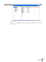
1
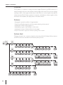
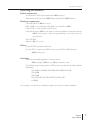
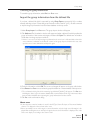
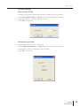
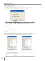
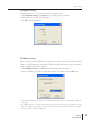
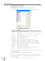
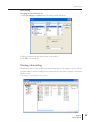
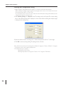
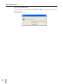
PJ Master
POA-PJNM01
Owner's Manual
Projectors and PDP Monitors Administrative Tool
Trademarks
The PJ Master is a trademark of Sanyo Electric Co., Ltd. Microsoft, Windows, Windows 2000, Windows
XP, Microsoft SQL Server 2000 Desktop Engine (MSDE2000A) are registered trademarks of Microsoft
Corporation. Other products or brand names in this manual are registered trademarks or trademarks
of their respective owners.
* Unauthorized use of a part or whole of the contents in this manual is prohibited.
* The contents of this manual are subject to change without notice.
2
Contents
Chapter 1 Introduction. . . . . . . . . . . . . . . . . . . . . . . . . . . . . . . . . 5
Overview . . . . . . . . . . . . . . . . . . . . . . . . . . . . . . . . . . . . . . . . . . . . . . . . . . . . 6
Features . . . . . . . . . . . . . . . . . . . . . . . . . . . . . . . . . . . . . . . . . . . . . . . . . . . . . . 6
System chart . . . . . . . . . . . . . . . . . . . . . . . . . . . . . . . . . . . . . . . . . . . . . . . . . . 6
Operating environment . . . . . . . . . . . . . . . . . . . . . . . . . . . . . . . . . . . . . . . . 7
Chapter 2 Setup. . . . . . . . . . . . . . . . . . . . . . . . . . . . . . . . . . . . . . . . . . . 9
Software installation. . . . . . . . . . . . . . . . . . . . . . . . . . . . . . . . . . . . . . . . . . . 10
Microsoft SQL Sever Desktop Engine 2000A installation . . . . . . . . . . . .10
PJ Master installation . . . . . . . . . . . . . . . . . . . . . . . . . . . . . . . . . . . . . . . . . .11
Service starting confirmation . . . . . . . . . . . . . . . . . . . . . . . . . . . . . . . . . . .14
Uninstallation . . . . . . . . . . . . . . . . . . . . . . . . . . . . . . . . . . . . . . . . . . . . . . . . 14
Chapter 3 Basic operation . . . . . . . . . . . . . . . . . . . . . . . . . . . 15
Launching PJ Master . . . . . . . . . . . . . . . . . . . . . . . . . . . . . . . . . . . . . . . . . . . 16
Name of status window . . . . . . . . . . . . . . . . . . . . . . . . . . . . . . . . . . . . . . . 16
Quitting PJ Master . . . . . . . . . . . . . . . . . . . . . . . . . . . . . . . . . . . . . . . . . . . . 16
Operation . . . . . . . . . . . . . . . . . . . . . . . . . . . . . . . . . . . . . . . . . . . . . . . . . . . 17
Menu tree . . . . . . . . . . . . . . . . . . . . . . . . . . . . . . . . . . . . . . . . . . . . . . . . . . . 17
Name of the buttons on the tool bar . . . . . . . . . . . . . . . . . . . . . . . . . . . . 18
Execution of the commands . . . . . . . . . . . . . . . . . . . . . . . . . . . . . . . . . . . . 18
Status display of icons . . . . . . . . . . . . . . . . . . . . . . . . . . . . . . . . . . . . . . . . . 18
When the alert occurs on the target or server . . . . . . . . . . . . . . . . . . . . 19
Creating the group information . . . . . . . . . . . . . . . . . . . . . . . . . . . . . . . . . 19
Adding the server and target . . . . . . . . . . . . . . . . . . . . . . . . . . . . . . . . . . . 19
Adding the top server . . . . . . . . . . . . . . . . . . . . . . . . . . . . . . . . . . . . . . . . .20
Adding the sub server . . . . . . . . . . . . . . . . . . . . . . . . . . . . . . . . . . . . . . . . .20
Important notice on license key entry . . . . . . . . . . . . . . . . . . . . . . . . . . .20
Editing the server information . . . . . . . . . . . . . . . . . . . . . . . . . . . . . . . . . .21
Deleting the server . . . . . . . . . . . . . . . . . . . . . . . . . . . . . . . . . . . . . . . . . . .21
Adding the target . . . . . . . . . . . . . . . . . . . . . . . . . . . . . . . . . . . . . . . . . . . . .21
Editing the target information . . . . . . . . . . . . . . . . . . . . . . . . . . . . . . . . . . .22
Deleting the target . . . . . . . . . . . . . . . . . . . . . . . . . . . . . . . . . . . . . . . . . . . .22
Reflecting the group information . . . . . . . . . . . . . . . . . . . . . . . . . . . . . . . .22
Canceling the group information . . . . . . . . . . . . . . . . . . . . . . . . . . . . . . . .23
Import the group information from the defined file . . . . . . . . . . . . . . . . 23
Export the group information . . . . . . . . . . . . . . . . . . . . . . . . . . . . . . . . . . 24
System setting. . . . . . . . . . . . . . . . . . . . . . . . . . . . . . . . . . . . . . . . . . . . . . . . 25
Interval time setting . . . . . . . . . . . . . . . . . . . . . . . . . . . . . . . . . . . . . . . . . . .25
Temperature selection . . . . . . . . . . . . . . . . . . . . . . . . . . . . . . . . . . . . . . . . .25
Warning reception setting. . . . . . . . . . . . . . . . . . . . . . . . . . . . . . . . . . . . . .26
When the warning occurs . . . . . . . . . . . . . . . . . . . . . . . . . . . . . . . . . . . . .26
Encryption setting . . . . . . . . . . . . . . . . . . . . . . . . . . . . . . . . . . . . . . . . . . . .27
PJ Master
Owner’s Manual
3
Contents
IP Address setting . . . . . . . . . . . . . . . . . . . . . . . . . . . . . . . . . . . . . . . . . . . . .27
Customizing the display columns . . . . . . . . . . . . . . . . . . . . . . . . . . . . . . . .28
Changing the status column indication . . . . . . . . . . . . . . . . . . . . . . . . . . .28
Font setting . . . . . . . . . . . . . . . . . . . . . . . . . . . . . . . . . . . . . . . . . . . . . . . . . .29
Changing fonts on the status list. . . . . . . . . . . . . . . . . . . . . . . . . . . . . . . . .29
Warning value setting . . . . . . . . . . . . . . . . . . . . . . . . . . . . . . . . . . . . . . . . . 29
Warning time/temperature setting . . . . . . . . . . . . . . . . . . . . . . . . . . . . . .30
Global setting . . . . . . . . . . . . . . . . . . . . . . . . . . . . . . . . . . . . . . . . . . . . . . . . 31
Sending a command . . . . . . . . . . . . . . . . . . . . . . . . . . . . . . . . . . . . . . . . . .31
Default commands for projector . . . . . . . . . . . . . . . . . . . . . . . . . . . . . . . .32
Default commands for PDP monitor. . . . . . . . . . . . . . . . . . . . . . . . . . . . .32
Editing the predefined command . . . . . . . . . . . . . . . . . . . . . . . . . . . . . . . .33
Condition setting . . . . . . . . . . . . . . . . . . . . . . . . . . . . . . . . . . . . . . . . . . . . .33
Condition setting example . . . . . . . . . . . . . . . . . . . . . . . . . . . . . . . . . . . . .34
Viewing the status, alert and logs . . . . . . . . . . . . . . . . . . . . . . . . . . . . . . . . 35
Viewing the status of target or server . . . . . . . . . . . . . . . . . . . . . . . . . . . . 35
Viewing the alert information. . . . . . . . . . . . . . . . . . . . . . . . . . . . . . . . . . . 36
Viewing the logs . . . . . . . . . . . . . . . . . . . . . . . . . . . . . . . . . . . . . . . . . . . . . . 36
Reading of Error log. . . . . . . . . . . . . . . . . . . . . . . . . . . . . . . . . . . . . . . . . . .36
Error message description (part of errors) . . . . . . . . . . . . . . . . . . . . . . .37
Reading of alert log . . . . . . . . . . . . . . . . . . . . . . . . . . . . . . . . . . . . . . . . . . .38
Changing the display for each log type . . . . . . . . . . . . . . . . . . . . . . . . . . .39
Reading of command history log . . . . . . . . . . . . . . . . . . . . . . . . . . . . . . . .40
Description of the command and data . . . . . . . . . . . . . . . . . . . . . . . . . . .40
Format of the command data . . . . . . . . . . . . . . . . . . . . . . . . . . . . . . . . . .41
Updating . . . . . . . . . . . . . . . . . . . . . . . . . . . . . . . . . . . . . . . . . . . . . . . . . . . . 41
PJ Master software updating . . . . . . . . . . . . . . . . . . . . . . . . . . . . . . . . . . . .41
Network Board firmware updating . . . . . . . . . . . . . . . . . . . . . . . . . . . . . .42
Projector firmware updating . . . . . . . . . . . . . . . . . . . . . . . . . . . . . . . . . . . .43
Version information . . . . . . . . . . . . . . . . . . . . . . . . . . . . . . . . . . . . . . . . . . . 44
Chapter 4 Advanced setting . . . . . . . . . . . . . . . . . . . . . . . . . 45
Customizing the command list . . . . . . . . . . . . . . . . . . . . . . . . . . . . . . . . . . 46
Define file for projector . . . . . . . . . . . . . . . . . . . . . . . . . . . . . . . . . . . . . . .46
Define file for PDP monitor . . . . . . . . . . . . . . . . . . . . . . . . . . . . . . . . . . . .47
Format of the define file . . . . . . . . . . . . . . . . . . . . . . . . . . . . . . . . . . . . . . .48
Example . . . . . . . . . . . . . . . . . . . . . . . . . . . . . . . . . . . . . . . . . . . . . . . . . . . . .48
Predefined command list . . . . . . . . . . . . . . . . . . . . . . . . . . . . . . . . . . . . . . 49
Executing commands . . . . . . . . . . . . . . . . . . . . . . . . . . . . . . . . . . . . . . . . . .49
Condition check commands and response . . . . . . . . . . . . . . . . . . . . . . . .50
Create the group information with a text file . . . . . . . . . . . . . . . . . . . . . 51
Network tree data format . . . . . . . . . . . . . . . . . . . . . . . . . . . . . . . . . . . . .51
Practical example of the defined file . . . . . . . . . . . . . . . . . . . . . . . . . . . . .51
4
Chapter 1 Introduction
1
PJ Master
Owner’s Manual
5
Chapter 1 Introduction
Overview
The PJ Master is a software to manage and control targets (Projectors and PDP monitors) in a
network centrally, and forms a tree structure with the targets and servers. The top server manages
operating condition of the targets centrally and provides functions to control targets and update the
software remotely. The PJ Master operates in cooperation with database software, registers all the
information in the database, and displays them on the status window.
Features
- Managing the operation condition of targets centrally.
- Central controlling the targets by serial command transferring via the network.
- Updating the firmware of the projectors *.
- Updating the program of the PJ Master on the servers.
- Updating the firmware of Network Board on the targets.
* Only the model which supports the firmware updating via the network.
System chart
Following example shows a system configuration chart using with the PJ Master. All the projectors
and PDP monitors are controlled and monitored by the top server.
Top Server
Server_A
Server_B
Proj_01
Proj_02
Proj_03
Proj_04
Proj_05
Server_E
Proj_06
Server_C
Server_D
Proj_401
6
Proj_402
Proj_101
Proj_201
Proj_102
Proj_202
Proj_103
Proj_203
Proj_301
Proj_302
Proj_303
Proj_403
Proj_404 Proj_405
Proj_104 Proj_105
Proj_204 Proj_205
Proj_304 Proj_305
Proj_406
Proj_407
Proj_07
Proj_08
Proj_09
Proj_10
Proj_x
Server_F
PDP_101
PDP_102
PDP_103
PDP_104
PDP_10x
PDP_201
PDP_202
PDP_203
PDP_204
PDP_20x
Server_G
Proj_30x
Proj_40x
Operating environment
Operating environment
System requirement
Server: Windows XP Professional, Windows 2000 Professional
Database: Microsoft SQL Server 2000 Desktop Engine (MSDE 2000) Release A
Hardware requirement
CPU: Intel Pentium III 400MHz or more
RAM: 128MB or more (Windows XP), 64MB or more (Windows 2000)
Display: XGA or more resolution and 256 colors
Hard disk: More than 100MB of free space for software installation, and another minimum
100MB of free space to store the logs depending on your environment for
usual operation
Drive: CD-ROM
Network: 10Base-T or more
Others
Protocol: TCP/IP and unique specification
Port use: 5871: for upper server, 5872: for lower server, 5873 and 5874: Reserved
10000 for telnet port
Limitation
Maximum connectable equipment in a network: Server:
1000 sets, Target: 15,000 sets, and 100 sets maximum/a node.
The PJ Master supports the projector or PDP monitor provided with the Network Board
listed below;
POA-PN01, POA-PN01A, POA-PN02, POA-PN03, POA-PN10,
POA-PN30,
POA-PN40,
POA-MD13NET, POA-MD13NET2, POA-MD19NET
KA-PN03
* It is required you must have an administrator rights to the server for software installation.
PJ Master
Owner’s Manual
7
Chapter 1 Introduction
8
Chapter 2 Setup
2
PJ Master
Owner’s Manual
9
Chapter 2 Setup
Software installation
The PJ Master consists of the database software “Microsoft SQL Server Desktop Engine 2000A” and
administrative tool “PJ Master” provided with graphic user interface. You need to install the above
software on a top server and sub servers following to the steps below.
Microsoft SQL Sever Desktop Engine 2000A installation
1. Double-click the Setup.exe icon in a folder “MSDE” in the CD-ROM.
2. The language selection dialog window appears. Select the language you wish to use and click OK.
3. The password entry window appears. Type password* and click Install to start installation.
10
Software installation
4. The dialog window appears to show you the installation status and remaining time.
After completing the installation, the dialog disappears.
5. Restart your computer.
6. After restarting your computer, check the MSDE Service Manager icon appears on the task bar.
PJ Master installation
1. Double-click the Setup.exe icon in a folder “PMS” in the CD-ROM.
2. The language selection dialog window appears.
Select the language you wish to use and click
OK. The installation wizard window appears.
Click Next to start installation.
PJ Master
Owner’s Manual
11
Chapter 2 Setup
3. Software License Agreement window appears. Thoroughly read the contents. If you agree to the
contents of the software license agreement, click Next.
4. Parameter window appears. Set parameters as below and click Next.
Item
Description
MSDE Password
IP Address
Connected event
Alert
Status
12
Enter the same password when used at the installation of the Microsoft
SQL Server Desktop Engine (p.10). You cannot install PJ Master software if
the password differs.
IP address of the computer appears automatically. If your computer provide
the multiple network cards, select an IP address which you want to use for
the PJ Master.
* If “127.0.0.1” appears, your computer is not connected to the network
correctly. Make sure that the LAN cable is connected to the computer and
try installation again.
Select “Alert” or “Status”.
Displays the event as Alert when the target is disconnected from the network.
Displays the event as Status when the target is disconnected from the network.
* See item “Reading of alert log” (p.38) for further information.
Software installation
5. Choose Destination Location window appears. Select the location and click Next.
6. Installation Information window appears. Confirm all the installation information and click Next
to start the installation.
7. When completing the installation, click Finish to close the installation window.
This is complete for the installation of software.
If you want to use PJ Master on the multiple servers, install software “Microsoft SQL Server Desktop
Engine 2000A” and “PJ Master” into each server following to the above procedure. It is also required
to have the license of PJ Master for each server.
PJ Master
Owner’s Manual
13
Chapter 2 Setup
Service starting confirmation
1. Open Control Panel, double click Administrative Tools icon and then double click Service icon.
The service control window will appear.
2. Confirm the following services are started as follows;
Name
Status
Startup Type
Log On AS
MSSQLSERVER
PMServer Service
Started
Started
Automatic
Automatic
LocalSyetem
LocalSyetem
Uninstallation
Take following steps to uninstall the software.
1. To remove Microsoft SQL Server Desktop Engine, perform it with “Add/Remove Programs” on
the control panel.
2. To remove the PJ Master, Select “Unisntallation” from the “Start” - “All Program” - “PJ Master”.
14
Chapter 3 Basic operation
3
PJ Master
Owner’s Manual
15
Chapter 3 Basic operation
Launching PJ Master
To launch the PJ Master, select “PJ Master” from “Start” - “All Programs” - “PJ Master”. The status
window will appear on the screen.
Make sure that the server is connected to the network and assigned a correct IP address before
launching the PJ Master. If the PJ Master cannot acquire the IP address, the IP Address setting dialog
will appear on the screen (p. 27).
Name of status window
Target
Status column
Menu
Tool
bar
Server
Tree view window
Status list view window
Number of acquisition times
System status
* The web-based setting page will appear on the
screen when double clicking the target.
Name
Description
Tree view window
Displays tree structure of the target servers
Status list view window Displays the status of the servers and targets which are linked to the
server selected on the tree view window
Status column
Column of the status. This can be customized (p.28).
Number of acquisition times Displays the number of acquisition times after the PJ Master starts
System status
Displays ERROR, ALERT or STATUS according to the last acquisition status
Quitting PJ Master
To quit the PJ Master, click the close button on top right of the window, or select Exit from Display
menu.
* This executes only window close. The monitoring still operates as background process.
16
Operation
Operation
When selecting a server on the tree view window, the linked targets or servers under the selected
server are listed on the status list view window. Their status information are acquired from the database in the top server and displayed on the status list view window.
After spending the predefined interval time* or executing Refresh command, the latest status information in the database in the selected server is displayed on the status list view window.
* See item “System Setting” for interval time (p.25).
Menu tree
Menu
Sub menu
Display
Status...
Alert...
Alert Export...
Log - Error...
Alert...
Operation
Displays selected target status on the status window (p.35)
Lists existing alert events on the alert window (p.36 )
Exports existing alert information as text file (csv file)
Lists error events on the error log window (p.36)
Lists alert events on the alert log window (p.38)
Command History... Lists command history on the history log window (p.40)
Refresh
Updates window information. When this command is executed, the PJ Master acquires target information from the database and displays them on the status window.The PJ Master
does not access the target or server directly to get the status,
so it may differ between the status displayed on the window
and the actual status of the target.
Tool bar...
Switches tool bar display on or off (p.18)
Exit
Quits the PJ Master
Projector Warning Setting...*
Sets warning value of use time and temperature (p.30)
Global Setting...*
Displays projector global setting window (p.31)
PDP
Global Setting...*
Displays PDP global setting window (p.31)
System
Group Edit...*
Registers servers and targets with tree construction (p.19)
Group Export...*
Exports the tree information of the servers and targets as
the csv file (p.24)
Interval Time Setting... Sets interval time to update the status list view window (p.25)
Temperature Selection... Selects temperature unit Celsius or Fahrenheit (p.25)
Warning Reception Setting... Sets warning reception type “Sound” and/or “Window” (p.26)
Encryption Setting...*
Sets encryption communication on or off (p.27)
Column Selection...
Selects display columns on the status list view window (p.28)
Font Setting...
Sets font on the status list view window (p.29)
IP Address Setting...
Selects an IP address manually (p.27)
Update
PJ Master Update...*
Used to update software PJ Master (p.41)
PJ-Net Update...*
Used to update firmware of the Network Board (p.42)
PJ Update...*
Used to update firmware of the projector or PDP (p.43)
Help
Version...
Displays the PJ Master version information (p.44)
* Only available at the top server.
PJ Master
Owner’s Manual
17
Chapter 3 Basic operation
Name of the buttons on the tool bar
The following commands are assigned to the buttons on the tool bar.
PJ Global setting
Status
PDP Global setting
Error log
Alert
Command history
Alert log
Button
Operation
PJ global setting
PDP global setting
Status
Alert
Error log
Alert log
Command history
Displays projector global setting window. (p.31)
Displays PDP global setting window. (p.31)
Displays selected target status on the status window (p.35)
Lists existing alert events on the alert window (p.36)
Lists error events on the error log window (p.36)
Lists alert events on the alert log window (p.38)
Lists command history on the history log window (p.40)
* To switch tool bar display on or off, select Tool bar from Display menu.
Execution of the commands
The PJ Master provides some kinds of ways to execute the commands. The PJ Master executes the
command assigned to the bottons on the tool bar, or command on the menu, or command on the
popup menu appeared by right-clicking with a mouse button.
Server icons
Status display of icons
Displays icon according to the target condition or server condition
Icon
Condition
Server
Gray
Red
Blue
Projector icons
Displays the sub server and targets linked to this server operate in normal
Displays the target linked to this server has an alert
Displays number of the disconnected targets placed under this server exceeds
defined disconnect number (p.20)
Target
PDP icons
18
Gray
Red
Blue
Displays the target operates in normal
Displays the target has an alert.
Displays number of the disconnected targets placed under the server exceeds
defined disconnect number (p.20)
* Top server icon displays red if one of the servers or targets in the network has an error.
Group editing
When the alert occurs on the target or server
If the abnormality or connection error occurs on the target (Projector or PDP monitor), the PJ Master
indicates target name and status column item with red to let you know the abnormality, also changes
color of icon to red.
If one of the targets has an alert, the icon color of upper server which that target is linked changes
to red. Its server brings up the alert information to the another upper server and finally the alert
information is brought up to the top server. The icon color of server including the top server on
which the alert is detected changes to red. So if the icon color of the top server is red, there may be
some alerts on targets in the network.
* To judge the condition of the target “Alert” or “Status” when the connection error occurs, it is according
to your selection of the connection event during the installation. (p.12)
Creating the group information
Adding the server and target
To add the server and target on the status window, first select Group Edit from System menu. The
group edit window appears as follows.
When adding, editing or deleting the server or target, perform it on this group edit window.
Server edit window
Target edit window
PJ Master
Owner’s Manual
19
Chapter 3 Basic operation
Adding the top server
1. Right-click on the server edit window and select Add on the popup menu. The new server registering window appears.
2. Enter the topserver information.
Item
Description
Server name
IP Address
Disconnect Number*1
Telnet Password*2
Name of the top server
Enter IP address assigned to the top server
0
Password for telnet connection to the target. Should be set the same login
password to the target.
Enter the product license key affixed on the Quick Setu Guide.
License Key*3
3. Click OK to set the information. The setting window will close.
*1 Disconnect Number is to specify the maximum number of the disconnected servers and targets
managed by the upper server. If the upper server detects disconnected targets more than this value,
the server judges that they are not ready to be controlled and leaves them from target monitoring.
The icon color of the server is changed to blue to show you the status.
*2 Unified login passward to the targets placed into the same group should be used.
*3 The PJ Master enable you to register a top server and up to 3 targets without license key for the
test purpose.
Adding the sub server
1. Right-click on a top server on the server edit window and select Add on the popup menu. The
new server registering window appears.
2. Enter the sub server information as the above of “Adding the top server”.
3. Click OK to set the information. The setting window will close. The server is registered under the
selected top server or sub server.
4. Repeat steps 1 to 3 to register the servers.
Important notice on license key entry
The license key is affixed on the Quick Setup Guide supplied with the CD-ROM. Each PJ Master on the
servers is required to register each license key. The entry of license key for the sub servers must be carried
out through the PJ Master on the top server otherwise the sub servers cannot join the top server group.
20
Group editing
Editing the server information
1. Select the server you intend to edit server information. Right-click on it and then select Edit on
the popup menu. The edit server window appears.
2. Edit server information on the window.
3. Click OK to set the information. The edit window will close.
Deleting the server
1. Select the server you intend to delete. Right-click on it and then select Delete on the popup menu.
2. Click Yes on the confirmation dialog.
Adding the target
1. Select the top server or sub server under which you intend to place the target. If the target is
registered under the selected server, the target icon will appear on the target edit window.
2. Right-click on the target edit window and select Add on the popup menu. The target registering
window appears.
3. Select target either PJ or PDP, and enter target name and IP address.
4. Click OK to set the information. The setting window will close. The registered target will be listed
on the target edit window.
PJ Master
Owner’s Manual
21
Chapter 3 Basic operation
Editing the target information
1. Right-click on the target and then select Edit on the popup menu. The edit target window appears.
2. Edit target name or IP address on the edit target window. The target type PJ or PDP cannot be changed.
3. Click OK to set the information. The edit window will close.
Deleting the target
1. Select the target you intend to delete. Right-click on it and then select Delete on the popup
menu.
2. Click Yes on the confirmation dialog.
Reflecting the group information
1. After completing registering the group information, select Execute from Proc menu to reflect the
group information into a master database in the top server.
2. Click Yes on the confirmation dialog.
* When the tree information is restructured, the PJ Master discards the untreated commands.
* When the IP address registered as the top server differs from the IP address assiged to the server provides the PJ Master, the group information cannot be reflected onto the status window of the PJ Master.
22
Group editing
Canceling the group information
To cancel the group information, select Exit from Proc menu.
Import the group information from the defined file
If you have a defined file which is exported by using Group Export command (p.24) or written
manually referring to item “Create the group information with a text file” (p.51), use this command
to import the group information into the master database on the top server.
1. Select Group Import from Proc menu. The group import window will appear.
2. Click Reference. The file selection window will appear and select a defined file which provides the
group information of the servers and targets, and then click Open. The defined tree information
will be listed on the group import window.
* If there is an error in the imported group information, the error item is indicated with red and the
error comment is indicated on the “Result” column on the group import window. In this case, clear
up all the errors in the defined file and import it again.
3. Check the information and click OK. The servers and targets will appear on the group edit window.
4. Select Execute from Proc menu to reflect the group information into a master database in the top server.
* The confirmation dialog “Are all the mastering logs initialized? [Yes/No]” will appear. Click Yes when
initializing the all the logs in the master database. We recommend that all the logs in the master database should be initialized when importing the group information from the text file.
5. Click Yes on the confirmation dialog.
About error
* If other than the numerical number is used for the ID, Type, Parent ID, Layer, or Disconnect Number
column, “*” is displayed on that column as the error.
* If there are multiple errors on the target or server information, only the single error information is displayed. After resolting that error and import it again, the next error information is displayed. The order
of the error display is according to the column order.
PJ Master
Owner’s Manual
23
Chapter 3 Basic operation
Export the group information
The PJ Master allows you to export the group information in the top server as the text file. Click
Group Export from System menu, and select a destination to save the file. This text file contains the
information as table below. It is recommended that after creating the group information with Group
Edit command, export the latest group information for the backup.
For further information of the column, see item “Create the group informatin with a text file”
(p.51).
Column
Description (example)
ID code
Target name
Sequence number (1,2,3,4.....)
Server name or Target Name (Server_A, Server_B, Proj_01, Proj_02.
PDP_10)
0: Server, 1: Projector, 2: PDP (0,1,2)
Assigned IP address (192.168.0.1,)
ID of the server to which the target links. The top server should be set “0”
0: top layer, 1: 2nd layer, 2: 3rd layer,...(0,1,2,3..)
Number of disconnected targets (1,2,3,4,5...)
Password for telnet login to the target (blank: no password)
License key code for the PJ Master
(2005-05-28 12:15:00)
Target property
IP Address
Parent ID code
Layer
Disconnect number
Telnet password
Licens key
Updated Date
24
System setting
System setting
Interval time setting
Setting the interval time to update the information on the status list view window.
1. Select Interval Time Setting from System menu. The setting window will appear.
2. Enter interval time. 1 to 9999 minutes can be used.
3. Click OK to set the time.
Temperature selection
Setting temperature unit Celsius or Fahrenheit
1. Select Temperature Selection from System menu. The setting window will appear.
2. Select either “Celsius” or “Fahrenheit” with radio button.
3. Click OK to set the unit.
PJ Master
Owner’s Manual
25
Chapter 3 Basic operation
Warning reception setting
Setting warning reception action type when the warning occurs.
1. Select Warning Reception Setting from System menu. The setting window will appear.
2. Tick the action type “Sound warning alarm” and/or “Display warning dialog”.
Item
Description
Sound warning alarm
Display warning dialog
Warning alarm sounds when the warning occurs
Warning dialog window appears when the warning occurs
3. Click OK to set.
When the warning occurs
If the status change, alert or error occurs and the item “Display warning dialog” is ticked at the warining reception setting, the following warning information window appears on the screen.
Alert dialog window
* The value indicated with red shows the
alert has occur. The value indicated with
blue shows the alert has been resolved.
26
Status Change dialog window
* Warning value is indicated with green.
Item
Description
Number of reception
Number of reception times after the warning dialog appears
System setting
Encryption setting
Setting Encryption on or off for the communication between servers.
1. Select Encryption Setting from System menu. The setting window will appear.
2. Select either “On” or “Off ” with radio button.
3. Click OK to set the encryption.
IP Address setting
When the server provides multiple network cards and you want to change the IP address for the PJ
Master, or the PJ Master cannot acquire the IP address assigned to the server, use this command to
change or acquire the IP address manually.
1. Select IP Address Setting from System menu. The setting window will appear.
2. Select an IP Address you want to set with the pull-down menu button. and click OK button.
* The multiple IP addresses are listed on the pull-down menu button if the server provides multiple network cards.
* If “127.0.0.1” appear on the pull-down button, the server may not connect to the network correctly.
Make sure that the network cable is connected to the server correctly and the IP address is assigned to
the server, and then restart the PJ Master.
PJ Master
Owner’s Manual
27
Chapter 3 Basic operation
Customizing the display columns
Changing the status column indication
1. Select Column Selection from System menu. The setting window will appear.
2. On the window, check the column name you want to display on the status list view window .
Column
Description
Target Name
Power Status
Name of the network equipment
Status of the network equipment (ON:Normal, OFF:Normal, OFF:P-Mng, Cooling,
CountDown, etc.)
Status of lamp (On, Off, Err, LampNonLight, etc. indicated with lamp1, lamp2, lamp3,
lamp4 sequentially)
Name of input signal (Analog, Digital, S-Video, Video, Y/Cr/Cb, Y/Pr/Pb, etc.)
Status of input signal (On, Off, Interrupted)
Displays input mode (1,2,3 etc)
Status of network connection (Disconnect, Connect)
Displays inside temperature A of the equipment (in Celsius or Fahrenheit)
Displays inside temperature B of the equipment (in Celsius or Fahrenheit)
Displays inside temperature C of the equipment (in Celsius or Fahrenheit)
Displays lamp use time (Indicated with lamp1, lamp2, lamp3, lamp4 sequentially)
Displays IP address of the equipment
Displays model name of the equipment
Displays accumulated projector use time
Displays the version of the PJ Master or Network Board firmware
Displays the version of the projector firmware
Lamp Status
Input Signal
Input Status
Input Select
Network Status
Temperature A
Temperature B
Temperature C
Lamp Time
IP Address
Model Name
Projector Time
PJ-Net Ver.
PJ Ver.
3. To change order of the display column on the status list, select column you intend to change order
and click To up or To down.
4. Click OK to set the display column. The setting window will close.
28
* When specifying the column width by numeric value, enter number (0 to 9999) onto “Column width” text box.
* When changing the column width or column order on the status list view window, it is reflected to the
column selection window.
* Some of the column items may not effective depending on the connected target.
Warning setting
Font setting
Changing fonts on the status list
1. Select Font Setting from System menu. The setting window will appear.
2. Select your desired font face, style and size on the window.
3. Click OK to close window.
Warning value setting
The threshold value of lamp use time and internal temperatures of the target are set up with this
procedure. When it reaches a setting time or temperature, the alert will be displayed on the status
list view window.
* This setting is only effective for the projector.
PJ Master
Owner’s Manual
29
Chapter 3 Basic operation
Warning time/temperature setting
1. Select a target on the status list view window or a server on the tree view window.
- When setting the multiple targets together, select targets and/or servers on the status list view window with pressing “Shift” or “Control” key.
- If you select the server on the tree view or status list view window, the setting will be effected to the
targets linked under the selected server.
2. Select Warning Setting from Projector menu. The setting window will appear. The current setting
value of the selected target will be displayed on the window. When selecting the multiple target,
it displays the last setting value.
3. Enter the threshold value of warning time, or internal temperatures A, B or C of the target.
4. Click OK to set the warning setting. The setting window will close.
* 0 to 99999 hours can be set for warning time, and 0 to 99.9 degrees in Celsius or 32.0 to 211.9 degrees
in Fahrenheit can be set for warning temperature.
* The default values are as follows;
Warning Time: 99999 hours
Warning Temperature: 99.9 degrees in Celsius or 211.9 degrees in Fahrenheit
30
Global setting
Global setting
The PJ Master controls target by sending the specified control command via the network. The PJ
Master provides 24 kinds of basic commands for projector and 6 kinds of basic commands for PDP
monitor initially. You can also edit their commands or add new commands easily according to your
projector , PDP monitor or usage.
Sending a command
1. Select a target on the status list view window or a server on the tree view window.
- When setting the multiple targets together, select targets and/or servers on the status list view window with pressing “Shift” or “Control” key.
- If you select the server on the tree view or status list view window, the setting will be effected to the
targets linked under the selected server.
2. Click
or
button on the tool bar or select Global Setting from Projector or PDP menu.
The setting window will appear.
- The commands which are not effective to the selection are disabled.
3. Tick check boxes next to the title name and then click OK to execute the command. The setting
window closes.
4. After that the targets will operate according to the sending commands.
* If there are some errors on the targets or servers, the PJ Master receives error information from the
servers or targets and indicates further details on the error log window. See item “Reading of error log”
for further information. (p.36)
PJ Master
Owner’s Manual
31
Chapter 3 Basic operation
Default commands for projector
TITLE
TEXT
POWER ON
POWER OFF
VOLUME UP
VOLUME DOWN
MENU ON MODE
MENU OFF MODE
DATE SETTING
TIME SETTING
SCREEN NORMAL
SCREEN WIDE
BLUE BACK ON
BLUE BACK OFF
DISPLAY ON
DISPLAY OFF
LOGO ON
LOGO OFF
POWER MANAGEMENT ON
POWER MANAGEMENT OFF
PJ NAME SETTING
SMTP SETTING
ADMINI ADDRESS SETTING
MAIL1 ADDRESS SETTING
FANSPEED MAX
FANSPPED NORMAL
C00
C01
C09
C0A
C1C
C1D
LF DATE yyyy/mm/dd
LF TIME hh:mm
CF SCREEN NORMAL
CF SCREEN WIDE
CF BBACK ON
CF BBACK OFF
CF DISP ON
CF DISP OFF
CF LOGO ON
CF LOGO OFF
CF P-MANE ON
CF P-MANE OFF
LF PRJNAME PROJECTOR1
LF SMTP 192.168.0.1
LF ADMIN admini@your company name
LF MAIL1 user@your company name
CF FANSPEED MAX
CF FANSPEED NOR
Default commands for PDP monitor
TITLE
TEXT
POWER ON
POWER OFF
VOLUME UP
VOLUME DOWN
MENU ON MODE
MENU OFF MODE
C00
C01
C09
C0A
C1C
C1D
* You can define new commands, see item “Customizing the command list” on chapter 4. (p.46)
32
Global setting
Editing the predefined command
When changing the command according to the target or resetting date or time to the targets, take
the following steps;
1. Select a target on the status list view window or a server on the tree view window.
2. Click
or
button on the tool bar or select Global Setting from Projector or PDP menu.
The setting window will appear.
- The commands which are not effective to the selection are disabled.
3. Double click on a command title name you intend to change. The editing window will appear.
4. Change command on the text box and click OK to assign the command.
5. Tick check box next to its title name and click OK to execute the command. The setting window
will close. The edited command is set as the default command.
* The command data are stored in the defined files, Define_PJ.def for projector or Define_PDP.def
for PDP monitor, in the folder PMS/Program. If you want to add the new command, enable you to
edit these defined files. For further information, see “Customizing the command list” on chapter 4
(p.46).
Condition setting
By using the condition function, when executing the command defined by the Global Setting, it is
possible to set as its command is executed after checking the target status.
For example: Set screen mode to “Wide” for model “PLC-XP50” only.
At first, check if the model name of the targets is “PLC-XP50”, and then check if the target is in the
power-on mode, after that execute the command “Screen Wide”.
* Check the power status before executing the screen mode change command as it is not possible
to change the screen mode if the projector is in the stand-by mode.
* The maximum length of the command text including the condition text is 512 characters.
PJ Master
Owner’s Manual
33
Chapter 3 Basic operation
Condition setting example
1. Select a target on the status list view window or a server on the tree view window.
2. Click
or
button on the tool bar or select Global Setting from Projector or PDP menu.
The setting window will appear.
- The commands which are not effective to the selection are disabled.
3. Click Condition to open the condition setting window.
4. Click Add to open another setting window. Enter command and status, and set retry on or off.
Item
Setting example
Command:
CR MODELNM
Status:
PLC-XP50
Retry:
OFF
-- only execute command once.
* The above condition is to check if the model name of the targets is “PLC-XP50”.
5. Click OK to register a new condition command. The new command list appears in the command
condition window.
6. Repeat 4 to 5 steps for another commands.
Item
Setting example
Command:
CR0
Status:
00
Retry:
ON -- execute command “CR0” repeatedly until the status is “00”.
* The above condition is to check if the power status of the targets is “Power-On”.
7. Tick check box next to the command names you want to use for condition check.
8. Click OK to set the condition command.
34
Viewing the status, alert and logs
9. Tick check box next to the command name.
SCREEN WIDE CF SCREEN WIDE
10. Click OK to execute the command.
The screen mode of the projectors provided with model name “PLC-XP50” will be changed to
“Wide”.
* For further details of commands and status, described on item “Predefined command list” on chapter
4 (p.49).
* If there are projectors model PLC-XP50 in the network and those projectors are in the stand-by mode
at the command executed time, that command will execute when the projector turns on.
Viewing the status, alert and logs
Viewing the status of target or server
Displays the present status of target or server in the network.
1. Select a target or server you wish to display the status.
2. Select Status from Display menu or click
button on the tool bar. The status screen window
will appear and all the status of the items are displayed. If there is the warning item on the target
or server in the network, the warning information is indicated as follows;
Value indicated with red : Alert occured
Value indicated with green :Status changed
Value indicated with blue : Alert resolved
Server status
Target status
3. Click Close to close the window.
* The display order of the items on the status screen window is according to the column order of status
list view window. To change the order, see item “Customizing the display columns” (p. 28).
* The status of the last selected target or server will be displayed when selecting multiple targets or servers.
PJ Master
Owner’s Manual
35
Chapter 3 Basic operation
Viewing the alert information
Displays the present alert information of the targets or servers in the network.
1. Select Alert from Display menu or click
button on the tool bar. The alert display window will
appear to indicate the alert information. If there is the alert on the target or server in the network,
the alert item is indicated with red.
2. Click Export to export the alert information as text file (csv file).
3. Click Close to close the window.
* In the exported csv file, information which alert occured is indicated with @.
Viewing the logs
The PJ Master provides 3 types of logs Error log, Alert log and Command history log.
Select each command from menu Display - Log. Each log window will appear.
To export the error or alert logs as text file (csv file), click Export on its own log window.
* In the exported csv file, the colum items are placed on the 1st row.
Reading of Error log
Displays the error logs to all the command execution result on the servers.
Select Error from Display - Log menu or click
button on the tool bar. Before executing the Error
Log command, first select a top server, a sub server or a target.The error logs on the selected server
or target will be displayed on the error log screen window.
36
Item
Description
Server Name
Target Name
Error Detail
Execute Date
The name of the server which manages the target which had an error.
The name of the target which had an error.
Target communication error. ( SCREEN WIDE,res=?) *See next page
Date of command executed
Viewing the status, alert and logs
Error message description (part of errors)
There are some error comments on the error detail column as follows;
Global setting error
Error Message
Target command send error. (cmd=XXX*1)
Description
Failed to send the command.
Target command receive error. (cmd=XXX) Failed to receive the command
Target command communication error.
(cmd=XXX,res=YYY*2)
Unexpected response to the command
Condition setting error
Error Message
Target condition command send error.
(cmd=XXX)
Target condition command receive error.
(cmd=XXX)
Target condition command communication error. (cmd=XXX, res=YYY)
Target condition command communication error. (cmd=XXX, res=YYY:ZZZ*3)
Description
Failed to send the condition command
Failed to receive the condition command
Unexpected response to the condition command
Unexpected response to the condition command
*1 XXX means each command name.
*2 YYY means response to the command.
*3 ZZZ means expected response to the command.
PJ update error
Error Message
Update PJ file error.
Description
The PJ Master failed to update firmware of the projector.
Update PJ FTP error
FTP error during updating firmware of the projector.
PJ-Net update error
Error Message
Update PJ-Net write error.
Description
Failed to create PJ-Net file
Update PJ-Net file error.
Failed to update PJ-Net file or file type
Update PJ-Net FTP error.
FTP error during updating firmware of the Network
Board
PJ Master update error
Error Message
Update PJ Master Error.
Failed to start the program.
Update PJ Master Error.
The version is not the same.
Update PJ Master Error.
Failed to stop the service.
Update PJ Master Error.
Failed to copy the file.
Update PJ Master Error.
Failed to run batch file.
Update PJ Master Error.
Failed to start the service.
Update PJ Master Error.
Internal error occurred.
Description
Failed to start the update program
The PJ Master version error
Failed to stop the service
Failed to copy the update files
Failed to run the batch file
Failed to start the service.
Internal error occurred.
PJ Master
Owner’s Manual
37
Chapter 3 Basic operation
Reading of alert log
Displays the alert logs. Records the information when the alert occurs and is canceled.
Select Alert from Display - Log menu or click
button on the tool bar.
Before executing the Alert Log command, first select a top server, a sub server or a target. The alert
logs on the selected server or target will be displayed on the alert log screen window.
If there is the alert item on the target or server in the network, the alert information is indicated as
follows;
Value indicated with red : Alert occurred
Value indicated with green : Status changed
Value indicated with blue : Alert has been resolved
Item
Description
Server Name
Target Name
Power Status
Lamp Status
The name of the server which manages the target which had an alert.
The name of the target which had an alert.
Status of the network equipment (Power-on, StandBy, Cooling, CountDown, etc.)
Status of lamp (On, Off, Error, Replace, indicated with lamp1, lamp2, lamp3, lamp4
sequentially)
Name of input signal (Analog, Digital, S-Video, Video, Y/Cr/Cb, Y/Pr/Pb, etc.)
Status of input signal (On, Off, Interrupted)
Displays input mode (1,2,3 etc)
Status of network connection (Disconnect, Connect)
Displays inside temperature A of the equipment (in Celsius or Fahrenheit)
Displays inside temperature B of the equipment (in Celsius or Fahrenheit)
Displays inside temperature C of the equipment (in Celsius or Fahrenheit)
Displays lamp use time (lamp1, lamp2, lamp3, lamp4)
Displays IP address of the equipment
Displays model name of the equipment
Displays accumulated projector use time
Displays the version of the Network Board firmware or PJ Master
Displays the firmware version of the projector
Displays the aleart occured date
Input Signal
Input Status
Input Select
Network Status
Temperature A
Temperature B
Temperature C
Lamp Time
IP Address
Model Name
Projector Time
PJ-Net Ver.
PJ Ver.
Execute Date
38
* In the csv file, information which alert occurred is indicated with @, information which alert has been
resolved is indicated with # and information which status changed is indicated with *.
* The alert log of the last selected target or server will be displayed when selecting multiple targets or servers.
Viewing the status, alert and logs
Changing the display for each log type
Click Select on the alertlog screen wondow.The log type selection window will appear. Tick the type
“Alert” and/or “Status change” and then click OK.
The contents on the alert log window will change according to the above selection.
* To judge the condition of the target “Alert” or “Status” when the connection error occurs, it is according
to your selection of the connection event during the installation. (p.12)
* When un-checking both of them, it will be the same treatment when checking both of them.
Alert log screen window when selecting “Alert” type
Alert log screen window when selecting “Status change” type
PJ Master
Owner’s Manual
39
Chapter 3 Basic operation
Reading of command history log
Displays the command executing history on the own server.
Select Command History from Display - Log menu or click
button on the tool bar.
Item
Description
Command
Target
Destination
Source
Command Data
Name of the executing command. * See table below.
Name of the target or server to send the command. (Proj_05)
Name of the server to execute the command finally. (server name) (broadcast)
Name of the top server (top server name)
Command data (C01, C00, CF SCREEN WIDE%CR MODELNM=PLCXP50=0&CR STATUS=0=1) * See table below.
Result of the command execution. success: OK, failure: NG, retry : blank
Command executed date
Result
Execute Date
Description of the command and data
40
Command
Update Group Info
Command data
none
Warning Setting(PJ)
(Warning Time) (Warning temperature A) (Warning temperature B)
(Warning temperature C)
Global Setting(PJ)
Global Setting(PDP)
(Global setting command) % (Condition)
PJ Master Update
PJ-Net Update
PJ Update
PJ Net Master V(version)
(Binary file name) % (Condition)
(Binary file name) % (Condition)
Updating
Format of the command data
The format of the command data is as follows;
Global Setting Command
Condition Setting Command
CF SCREEN WIDE%CR MODELNM=PLC-XP50=0&CR STATUS=0=1
q
q
w
e
r
t
y
w
e
r
t
y
Global setting command: change screen mode to “WIDE” (CF SCREEN WIDE)
“%” Connection mark between global setting command and condition setting command.
1st condition setting command (CR MODELNM=PLC-XP50=0)
“&” Connection mark between condition setting commands
2nd condition setting command (CR STATUS=0)
Retry flag, 1=On, 0=Off
Updating
PJ Master software updating
Updates the PJ Master software in the multiple servers all at once.
Before taking the procedure below, set the CD-ROM provided with a new version of PM Master
software onto your computer.
1. Select a server you intend to update the PJ Master software. If you select a top server or a server
which has child servers, the servers under the selected server are targets to update the PJ Master
software.
2. Select PJ Master Update... from Update menu.
3. Browse and select a “Update.def ” file in the “US” -“PMS” folder in the CD-ROM.
4. Click Open and then the confirmation dialog will appear. Click Yes to execute updating the PJ
Master software.
- The updating command is sent to all the target servers to update the software at each server. On the
target server, the DOS prompt window appears on the screen to indicate the updating process. When
updating ended successfully, the prompt window closes automatically. If the PJ Master status window
is opening, it also closes automatically.
* To check that the PJ Master software was updated successfully, select Version from Help menu for the
top server, and check the version indication on “PJ-Net Ver.” column on the status list view window for
sub servers .
* If there are disconnected servers during command executing, the upper server monitors connection
status every 1 minute and keeps command until the command delivers to all the linked servers.
* For further information of the PJ Master update file, please consult your sales dealer.
PJ Master
Owner’s Manual
41
Chapter 3 Basic operation
Network Board firmware updating
Updates the firmware of the Network Board on the multiple targets all at once.
Before taking the procedure below, put a supplied binary file “****.bin” on the desktop of your
computer.
1. Select a target you intend to update the firmware of the Network Board. If you select a top server
or a server which has the targets, the targets under the selected server are targets to update
the firmware of the Network Board. Also you can select multiple targets on the status list view
window individually.
2. Select PJ-Net Update from Update menu.
3. Browse and select a prepared “****.bin” file on the desktop.
4. Click Open, and then the another confirmation dialog will appear.
5. Click Condition if you want to set condition command, or click OK if you want not to set the
condition command.
Take below steps if you click Condition.
5-1. The window to set the condition to execute the updating appears. This is the same setting
window used in the PJ Global Setting or PDP Global Setting.
5-2. Tick check box next to the command name you want to use for condition check.
* To make a new condition check command, click Add to open the edit condition window
and enter command and status, and set retry on or off. See item “Condition setting” (p.33)
for further details. Click OK to set a new condition. The setting window closes.
Condition
Command: CF PJ-NET VERSION
Status:001.001
Retry: OFF
5-3. Click OK to start updating.
The updating command is sent to all the target servers and each server starts updating the firmware
of the targets sequentially.
* To check that the firmware of the Network Board was updated successfully, check the version indication
on “PJ-Net Ver.” column on the status list view window.
* If there are disconnected servers during command executing, the upper server monitors connection
status every 1 minute and keeps command until the command delivers to all the linked servers.
* Updating is only executed when the ID in the update file coincides with the Network Board ID.
* For further information of the binary update file, please consult your sales dealer.
42
Updating
Projector firmware updating
Updates the firmware in the multiple projectors all at once.
Before taking the procedure below, put a supplied binary file “****.bin” on the desktop of your
computer.
1. Select a target you intend to update the firmware. If you select a top server or a server which has
the targets, the targets under the selected server are targets to update the firmware. Also you can
select multiple targets on the status list view window individually.
2. Select PJ Update from Update menu.
3. Browse and select a prepared “****.bin” file on the desktop.
4. Click Open to execute the updating. The another confirmation dialog will appear.
5. Click Condition if you want to set condition command, or click OK if you want not to set the
condition command.
Take below steps if you click Condition.
5-1. The window to set the condition to execute the updating appears. This is the same setting
window used in the PJ Global Setting.
5-2. Tick check box next to the command name you want to use for condition check.
* To make a new condition check command, click Add to open the edit condition window
and enter command and status, and set retry on or off. See item “Condition setting” (p.28)
for further details. Click OK to set a new condition. The setting window closes.
Condition 1
Command: CF STATUS
Status:80
Retry: ON
Condition 2
Command: CF MODELNM
Status:PLC-XF60
Retry: OFF
5-3. Click OK to start updating.
The updating command is sent to all the target servers and each server starts updating the firmware
of the projectors sequentially.
* To check that the firmware of the target was updated successfully, check the version indication on “PJ
Ver.” column on the status list view window.
* If there are disconnected servers during command executing, the upper server monitors connection
status every 1 minute and keeps command until the command is delivers to all the linked servers.
* If there are disconnected targets during command executing, the parent server monitors connection
status every 1 minute and keeps command until the connection is established.
* This command is only available if the projector supports updating via the network.
* For further information of the binary update file, please consult your sales dealer.
PJ Master
Owner’s Manual
43
Chapter 3 Basic operation
Version information
To display the version of the PJ Master, Select Version from Help menu.The following version display
dialog will appear.
Click OK to close the dialog.
44
Chapter 4 Advanced setting
4
PJ Master
Owner’s Manual
45
Chapter 4 Advanced setting
Customizing the command list
The available commands in the Global Setting menu are defined by the text file “Define_PJ.def ”
for projector or “Define_PDP.def ” for PDP monitor. They are located on folder “Program” in folder
“PMS”. When you change the TEXT(command) on the Global Setting window, this file will be updated automatically. If you want to add new commands, edit this file depending on your environment.
Define file for projector
The default setting in the “Define_PJ.def ” file is described as follows;
46
[GROUP LIST]
COUNT
GROUP1
GROUP2
GROUP3
GROUP4
GROUP5
GROUP6
GROUP7
GROUP8
GROUP9
GROUP10
GROUP11
GROUP12
GROUP13
GROUP14
GROUP15
= 15
= POWER
= VOLUME
= MENU
= DATE
= TIME
= SCREEN
= BLUEBACK
= DISPLAY
= LOGO
=PMANE
=PJNAME
=SMTP
=ADMINI
=MAIL1
=FANSPEED
[POWER]
SEC_MODE
POWER ON
POWER OFF
= EXCLUSIVE
=C00
=C01
[VOLUME]
SEC_MODE
VOLUME UP
VOLUME DOWN
= EXCLUSIVE
=C09
=C0A
[MENU]
SEC_MODE
MENU ON MODE
MENU OFF MODE
= EXCLUSIVE
=C1C
=C1D
[DATE]
DATE SETTING
=LF DATE 2003/11/29
[TIME]
TIME SETTING
=LF TIME 12:00
[SCREEN]
SEC_MODE
SCREEN NORMAL
SCREEN WIDE
= EXCLUSIVE
=CF SCREEN NORMAL
=CF SCREEN WIDE
[BLUEBACK]
SEC_MODE
BLUE BACK ON
BLUE BACK OFF
= EXCLUSIVE
=CF BBACK ON
=CF BBACK OFF
Customizing the command list
[DISPLAY]
SEC_MODE
DISPLAY ON
DISPLAY OFF
= EXCLUSIVE
=CF DISP ON
=CF DISP OFF
[LOGO]
SEC_MODE
LOGO ON
LOGO OFF
= EXCLUSIVE
=CF LOGO ON
=CF LOGO OFF
[PMANE]
SEC_MODE
POWER MANAGEMENT ON
POWER MANAGEMENT OFF
= EXCLUSIVE
=CF P-MANE ON
=CF P-MANE OFF
[PJNAME]
PJ NAME SETTING
=LF PRJNAME PROJECTOR1
[SMTP]
SMTP SETTING
=LF SMTP 192.168.0.1
[ADMINI]
ADMINI ADDRESS SETTING
=LF ADMIN [email protected]
[MAIL1]
MAIL1 ADDRESS SETTING
=LF MAIL1 [email protected]
[FANSPEED]
SEC_MODE
FANSPEED MAX
FANSPEED NORMAL
= EXCLUSIVE
=CF FANSPEED MAX
=CF FANSPEED NOR
Define file for PDP monitor
The default setting in the “Define_PDP.def ” file is described as follows;
[GROUP LIST]
COUNT
GROUP1
GROUP2
GROUP3
=3
= POWER
= VOLUME
= MENU
[POWER]
SEC_MODE
POWER ON
POWER OFF
= EXCLUSIVE
= C00
= C01
[VOLUME]
SEC_MODE
VOLUME UP
VOLUME DOWN
= EXCLUSIVE
= C09
= C0A
[MENU]
SEC_MODE
MENU ON MODE
MENU OFF MODE
= EXCLUSIVE
= C1C
= C1D
PJ Master
Owner’s Manual
47
Chapter 4 Advanced setting
Format of the define file
Describes the operators and format of the define file as follows;
[GROUP LIST]
COUNT = {number of the total group}
GROUP1 = {group name1}*1
GROUP2 = {group name2}
:
:
GROUPn = {group name n}
*1 Group name is a unique identifier.
[{group name 1}]
SEC_MODE = EXCLUSIVE *2
{command description1} = {command}
{command description2} = {command}
*2 Use when selecting an exclusive command among 2 or more
commands
[{group name 2}]
{command description} = {command}
:
:
[{group name n}]
{command description = {command}
Example
If you want to add a new command “INPUT SELECTION” in the “Global Setting”, edit “Define_PJ.
def ” file as follows;
Modify group number to “16”.
COUNT = 16
Add a new group number and group name.
GROUP16 = INPUT SELECTION
Add a new group specification
[INPUT SELECTION]
SEC_MODE = EXCLUSIVE
INPUT 1 = C05
INPUT 2 = C06
INPUT 3 = C07
INPUT 4 = C08
48
Predefined command list
Predefined command list
Executing commands
Command name
Command
Description
POWER ON
POWER OFF
VOLUME UP
VOLUME DOWN
MENU ON
MENU OFF
DATE SETTING
TIME SETTING
SCREEN NORMAL
SCREEN WIDE
SCREEN FULL
BLUE BACK ON
BLUE BACK OFF
DISPLAY ON
DISPLAY OFF
LOGO ON
LOGO OFF
POWER MANAGEMENT ON
POWER MANAGEMENT OFF
PROJECTOR NAME
SETTING
SMTP SETTING
ADMINISTRATOR
ADDRESS SETTING
MAIL1 ADDRESS
SETTING
FAN SPEED SETTING
MAXIMUM
FAN SPEED SETTING
NORMAL
INPUT 1 SELECTION
INPUT 2 SELECTION
INPUT 3 SELECTION
INPUT 4 SELECTION
C00
C01
C09
C0A
C1C
C1D
LF DATE YYYY/MM/DD
LF TIME hh:mm
CF SCREEN NORMAL
CF SCREEN WIDE
CF SCREEN FULL
CF BBACK ON
CF BBACK OFF
CF DISP ON
CF DISP OFF
CF LOGO ON
CF LOGO OFF
Turns on the target
Turns off the target
Increase sound volume one step
Decrease sound volume one step
Displays osd menu on the screen
Switches off osd menu on the screen
Sets date, ex:2005/05/18
Sets time, ex:16:45
Switches screen to “Normal”
Switches screen to “Wide”
Switches screen to “Full”
Sets blue back function on
Sets blue back function off
CF P-MANA ON
Sets power management function on
CF P-MANA OFF
Sets power management function off
LF PRJNAME xxxxxx
Sets projector name “xxxxxx”
LF SMTP 192.168.0.1
Sets smtp address “192.168.0.1”
LF ADMIN [email protected]
Sets administrator e-mail address
LF MAIL1 [email protected]
Sets e-mail address
CF FANSPEED MAX
Sets fan speed mode to maximum
CF FANSPEED NOR
Sets fan speed mode to normal
C05
C06
C07
C08
Sets input selection “Input 1”
Sets input selection “Input 2”
Sets input selection “Input 3”
Sets input selection “Input 4”
Sets logo display on while starting up
Sets logo display off while starting up
* Some kinds of commands may not effective or may differ depending on each model. For further information, please contact your sales dealer.
PJ Master
Owner’s Manual
49
Chapter 4 Advanced setting
Condition check commands and response
Command name
Command
Response
Power status check
00
80
CR0 or CR STATUS
40
20
Lamp status check
CR LAMPSTS
00
Description
Power on
Stand-by
Count down
Cooling
Lamp On, only available for multiple lamps
model.
Lamp off
Analog input
Digital input
S-video input
Video input
Signal exists
No signal
Selected input mode
Input source
CR SOURCE
Input status
CR SIGNAL
Input Select
Temperature
Lamp use time
Projector use time
Network board version
Model Name
CR INPUT
80, 40,20,10
ANALOG
DIGITAL
S-VIDEO
VIDEO
ON
OFF
1,2,3,4,5
CR TEMP
temperature
Actual temperature
CR LAMPH
time
Lamp use time in hours
CR PROJH
time
Accumulated use time in hours
LR PJNETVERSION
version number
Firmware version of network board
CR MODELNM
model name
Model name, “PLC-XF60” etc.
* Some kinds of commands may not effective or may differ depending on each model. For further information, please contact your sales dealer.
50
Create the network tree data with a text file
Create the group information with a text file
The PJ Master enables you to import the group information of the network from the text file which
defines the target and server information. To import the group information from the text files, prepare a defined file based on the format described on item ”Network tree data format” below. How
to import the defied file, refer to item “Import the group information from the defined file” (p.23).
Network tree data format
The defined file is a tab-deliminated file created with spreadsheet software and it is defined as follows. Refer to item “Practical example of defined file” below for further information.
Column
Description (example)
ID code
Target name
Sequence number (1,2,3,4.....)
Server name or Target Name (Server_A, Server_B, Proj_01, Proj_02.
PDP_10)
0: Server, 1: Projector, 2: PDP (0,1,2)
Assigned IP address (192.168.0.1,)
ID of the server to which the target links. The top server should be set “0”
0: top layer, 1: 2nd layer, 2: 3rd layer,...(0,1,2,3..)
Number of disconnected targets (1,2,3,4,5...)
Password for telnet login to the target (blank: no password)
License key code for the PJ Master
(2005-05-28 12:15:00)
Target property
IP Address
Parent ID code
Layer
Disconnect number
Telnet password
License key
Updated Date
Practical example of the defined file
Describes how to create the defined file if you setup the tree formatted network as the below
environment.
Layer=0
Top Server
Layer=1
Layer=2
Layer=3
Server_A
ID=0
(192.186.0.1)
ID=1
Server_B
Proj_01
Proj_02
Proj_03
Proj_04
Proj_05
Server_E
ID=8
Proj_06
Proj_07
Proj_08
Proj_09
Proj_10
ID=14
Server_C
Proj_101
Proj_102
Proj_103
Proj_104 Proj_105
Server_F
ID=20
PDP_101
PDP_102
PDP_103
PDP_104
PDP_201
PDP_202
PDP_203
PDP_204
ID=25
Server_D
Proj_201
Proj_202
Proj_203
Proj_204 Proj_205
Server_G
ID=31
ID=35
Proj_401
Proj_402
Proj_301
Proj_302
Proj_303
Proj_403
Proj_404 Proj_405
Proj_304 Proj_305
Proj_406
Proj_407
PJ Master
Owner’s Manual
51
Chapter 4 Advanced setting
The table below is an example of defined file created with spreadsheet software. Export it as the
tab-deliminated text file.
ID code
Disconnect number
Parent ID code
Telnet password
Layer
IP Address
License key
Target property
Target name
1
2
3
4
5
6
7
8
9
10
11
12
13
14
15
16
17
18
19
20
21
22
23
24
25
26
27
28
29
30
31
32
33
34
35
36
37
38
39
40
41
42
43
44
45
46
47
48
52
Top Server
Server A
Proj_01
Proj_02
Proj_03
Proj_04
Proj_05
Server E
Proj_06
Proj_07
Proj_08
Proj_09
Proj_10
Server B
Proj_101
Proj_102
Proj_103
Proj_104
Proj_105
Server F
PDP_101
PDP_102
PDP_103
PDP_104
Server C
Proj_201
Proj_202
Proj_203
Proj_204
Proj_205
Server G
PDP_201
PDP_202
PDP_203
PDP_204
Server D
Proj_301
Proj_302
Proj_303
Proj_304
Proj_305
Proj_401
Proj_402
Proj_403
Proj_404
Proj_405
Proj_406
Proj_407
0
0
1
1
1
1
1
0
1
1
1
1
1
0
1
1
1
1
1
0
2
2
2
2
0
1
1
1
1
1
0
2
2
2
2
0
1
1
1
1
1
1
1
1
1
1
1
1
192.168.0.1
192.168.0.2
192.168.0.3
192.168.0.4
192.168.0.5
192.168.0.6
192.168.0.7
192.168.0.8
192.168.0.9
192.168.0.10
192.168.0.11
192.168.0.12
192.168.0.13
192.168.0.14
192.168.0.15
192.168.0.16
192.168.0.17
192.168.0.18
192.168.0.19
192.168.0.20
192.168.0.21
192.168.0.22
192.168.0.23
192.168.0.24
192.168.0.25
192.168.0.26
192.168.0.27
192.168.0.28
192.168.0.29
192.168.0.30
192.168.0.31
192.168.0.32
192.168.0.33
192.168.0.34
192.168.0.35
192.168.0.36
192.168.0.37
192.168.0.38
192.168.0.39
192.168.0.40
192.168.0.41
192.168.0.42
192.168.0.43
192.168.0.44
192.168.0.45
192.168.0.46
192.168.0.47
192.168.0.48
0
1
2
2
2
2
2
2
8
8
8
8
8
1
14
14
14
14
14
14
20
20
20
20
1
25
25
25
25
25
25
31
31
31
31
1
36
36
36
36
36
1
1
1
1
1
1
1
0
1
2
2
2
2
2
2
3
3
3
3
3
1
2
2
2
2
2
2
3
3
3
3
1
2
2
2
2
2
2
3
3
3
3
1
2
2
2
2
2
1
1
1
1
1
1
1
5
5
5
5
5
5
5
5
5
5
5
5
5
5
5
5
5
5
5
5
5
5
5
5
5
5
5
5
5
5
5
5
5
5
5
5
5
5
5
5
5
5
5
5
5
5
5
5
xxxxx1-xxxxxA
xxxxx2-xxxxxB
xxxxx3-xxxxxC
xxxxx4-xxxxxxD
xxxxx5-xxxxxxE
xxxxx6-xxxxxxF
xxxxx7-xxxxxxG
xxxxx8-xxxxxxH
Updated Date
2005-05-28 12:15:00.00
2005-05-28 12:15:00.00
2005-05-28 12:15:00.00
2005-05-28 12:15:00.00
2005-05-28 12:15:00.00
2005-05-28 12:15:00.00
2005-05-28 12:15:00.00
2005-05-28 12:15:00.00
2005-05-28 12:15:00.00
2005-05-28 12:15:00.00
2005-05-28 12:15:00.00
2005-05-28 12:15:00.00
2005-05-28 12:15:00.00
2005-05-28 12:15:00.00
2005-05-28 12:15:00.00
2005-05-28 12:15:00.00
2005-05-28 12:15:00.00
2005-05-28 12:15:00.00
2005-05-28 12:15:00.00
2005-05-28 12:15:00.00
2005-05-28 12:15:00.00
2005-05-28 12:15:00.00
2005-05-28 12:15:00.00
2005-05-28 12:15:00.00
2005-05-28 12:15:00.00
2005-05-28 12:15:00.00
2005-05-28 12:15:00.00
2005-05-28 12:15:00.00
2005-05-28 12:15:00.00
2005-05-28 12:15:00.00
2005-05-28 12:15:00.00
2005-05-28 12:15:00.00
2005-05-28 12:15:00.00
2005-05-28 12:15:00.00
2005-05-28 12:15:00.00
2005-05-28 12:15:00.00
2005-05-28 12:15:00.00
2005-05-28 12:15:00.00
2005-05-28 12:15:00.00
2005-05-28 12:15:00.00
2005-05-28 12:15:00.00
2005-05-28 12:15:00.00
2005-05-28 12:15:00.00
2005-05-28 12:15:00.00
2005-05-28 12:15:00.00
2005-05-28 12:15:00.00
2005-05-28 12:15:00.00
2005-05-28 12:15:00.00
Create the network tree data with a text file
Select Group Edit from System menu, and select Group Import from Proc. menu. Select the created defined file of group information. The imported group information will appear on the group
edit window . Further details of procedure, refer to item “Import the group information from the
defined file” (p.23).
PJ Master
Owner’s Manual
53
1AA6P1P5082--a IFBY PJ Master v. 1.2
SANYO ELECTRIC Co., Ltd.