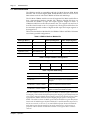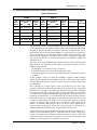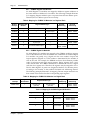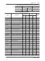
1
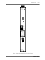
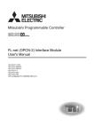
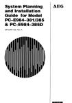
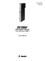
Instruction Bulletin
30598-822-01A1
August 1996
RIO Adapter Module
Class 8030 Type CRM931
User’s Manual
WARNING
UNINTENTIONAL EQUIPMENT OPERATION
The application of this product requires expertise in the design and programming of
control systems. Only persons with such expertise should be allowed to program, install,
alter, or apply this product.
Failure to observe this precaution can result in death or serious injury.
CAUTION
EQUIPMENT DAMAGE HAZARD
To avoid improper handling of equipment:
1. Never remove this device while power is ON. Turn power supply switch to OFF and
wait until all indicating lights are off before removing.
2. Do not subject to static discharge. This module contains electronic components that
are very susceptible to damage from electrostatic discharge.
Failure to observe this precaution can result in equipment damage.
SY/MAX is a registered trademark of Square D.
Modbus and Modsoft are registered trademarks of Modicon, Inc.
© 1996 Square D All Rights Reserved. This document may not be copied in whole or in part, or transferred to any
other media without the written permission of Square D.
Electrical equipment should be serviced only by qualified electrical maintenance personnel. No responsibility is
assumed by Square D for any consequences arising out of the use of this material.
30598-822-01A1
Page i
TABLE OF CONTENTS
TABLE OF CONTENTS . . . . . . . . . . . . . . . . . . . . . . . . . . . . . . . . . . . . . . . . . . . . . . . . . . . . . . . . . . . . . . i
LIST OF FIGURES AND TABLES . . . . . . . . . . . . . . . . . . . . . . . . . . . . . . . . . . . . . . . . . . . . . . . . . . . . . ii
1 OVERVIEW . . . . . . . . . . . . . . . . . . . . . . . . . . . . . . . . . . . . . . . . . . . . . . . . . . . . . . . . . . . . . . . . . . . . 1
1.1 GENERAL INFORMATION . . . . . . . . . . . . . . . . . . . . . . . . . . . . . . . . . . . . . . . . . . . . . . . . . . . . . . . . 1
1.2 RIO DROP MODULE FEATURES . . . . . . . . . . . . . . . . . . . . . . . . . . . . . . . . . . . . . . . . . . . . . . . . . . 2
1.3 WHERE TO FIND ADDITIONAL INFORMATION . . . . . . . . . . . . . . . . . . . . . . . . . . . . . . . . . . . . . . . 2
1.4 TERMINOLOGY USED IN THIS MANUAL . . . . . . . . . . . . . . . . . . . . . . . . . . . . . . . . . . . . . . . . . . . . 2
2 SPECIFICATIONS . . . . . . . . . . . . . . . . . . . . . . . . . . . . . . . . . . . . . . . . . . . . . . . . . . . . . . . . . . . . . . 5
2.1 COMPLIANCE INFORMATION . . . . . . . . . . . . . . . . . . . . . . . . . . . . . . . . . . . . . . . . . . . . . . . . . . . . 5
2.2 ELECTRICAL SPECIFICATIONS . . . . . . . . . . . . . . . . . . . . . . . . . . . . . . . . . . . . . . . . . . . . . . . . . . . 5
2.3 ENVIRONMENTAL SPECIFICATIONS . . . . . . . . . . . . . . . . . . . . . . . . . . . . . . . . . . . . . . . . . . . . . . 5
2.4 PHYSICAL SPECIFICATIONS . . . . . . . . . . . . . . . . . . . . . . . . . . . . . . . . . . . . . . . . . . . . . . . . . . . . . 5
2.5 FUNCTIONAL SPECIFICATIONS . . . . . . . . . . . . . . . . . . . . . . . . . . . . . . . . . . . . . . . . . . . . . . . . . .
2.5.1 Register Capabilities . . . . . . . . . . . . . . . . . . . . . . . . . . . . . . . . . . . . . . . . . . . . . . . . . . . . . . .
2.5.2 Communications Capabilities . . . . . . . . . . . . . . . . . . . . . . . . . . . . . . . . . . . . . . . . . . . . . . . . .
2.5.3 Supported Processor Types . . . . . . . . . . . . . . . . . . . . . . . . . . . . . . . . . . . . . . . . . . . . . . . . . .
2.5.4 Compatibility with SY/MAX Racks . . . . . . . . . . . . . . . . . . . . . . . . . . . . . . . . . . . . . . . . . . . . .
5
5
6
6
6
2.6 RESPONSE TIMES . . . . . . . . . . . . . . . . . . . . . . . . . . . . . . . . . . . . . . . . . . . . . . . . . . . . . . . . . . . . . 7
3 INSTALLATION . . . . . . . . . . . . . . . . . . . . . . . . . . . . . . . . . . . . . . . . . . . . . . . . . . . . . . . . . . . . . . . . 9
3.1 GENERAL INFORMATION . . . . . . . . . . . . . . . . . . . . . . . . . . . . . . . . . . . . . . . . . . . . . . . . . . . . . . . . 9
3.2 KEYING THE RACK . . . . . . . . . . . . . . . . . . . . . . . . . . . . . . . . . . . . . . . . . . . . . . . . . . . . . . . . . . . . . 9
3.3 SETTING MODULE SWITCHES . . . . . . . . . . . . . . . . . . . . . . . . . . . . . . . . . . . . . . . . . . . . . . . . . . 10
3.4 INSTALLING THE MODULE . . . . . . . . . . . . . . . . . . . . . . . . . . . . . . . . . . . . . . . . . . . . . . . . . . . . . . 10
3.5 WIRING THE CRM931 FOR THE RIO NETWORK . . . . . . . . . . . . . . . . . . . . . . . . . . . . . . . . . . . . 10
3.6 POWERING UP THE RIO ADAPTER MODULE . . . . . . . . . . . . . . . . . . . . . . . . . . . . . . . . . . . . . . 11
3.7 RIO DROP HARDWARE START-UP CHECKLIST . . . . . . . . . . . . . . . . . . . . . . . . . . . . . . . . . . . . 11
4 OPERATION . . . . . . . . . . . . . . . . . . . . . . . . . . . . . . . . . . . . . . . . . . . . . . . . . . . . . . . . . . . . . . . . . . 13
4.1 GENERAL INFORMATION . . . . . . . . . . . . . . . . . . . . . . . . . . . . . . . . . . . . . . . . . . . . . . . . . . . . . . . 13
4.2 RIO DROP REGISTERS . . . . . . . . . . . . . . . . . . . . . . . . . . . . . . . . . . . . . . . . . . . . . . . . . . . . . . . . . 13
4.3 REMOTE I/O BEHAVIOR . . . . . . . . . . . . . . . . . . . . . . . . . . . . . . . . . . . . . . . . . . . . . . . . . . . . . . . . 13
4.4 RACK ADDRESSING . . . . . . . . . . . . . . . . . . . . . . . . . . . . . . . . . . . . . . . . . . . . . . . . . . . . . . . . . . . 14
4.5 USING A MODICON PLC WITH A SY/MAX I/O MODULE . . . . . . . . . . . . . . . . . . . . . . . . . . . . . . . 15
4.5.1 SY/MAX Register I/O Modules . . . . . . . . . . . . . . . . . . . . . . . . . . . . . . . . . . . . . . . . . . . . . . . 16
4.5.2 SY/MAX Digital I/O Modules . . . . . . . . . . . . . . . . . . . . . . . . . . . . . . . . . . . . . . . . . . . . . . . . 16
5 TROUBLESHOOTING . . . . . . . . . . . . . . . . . . . . . . . . . . . . . . . . . . . . . . . . . . . . . . . . . . . . . . . . . . 19
5.1 GENERAL INFORMATION . . . . . . . . . . . . . . . . . . . . . . . . . . . . . . . . . . . . . . . . . . . . . . . . . . . . . . . 19
5.2 PROGRAMMING EQUIPMENT . . . . . . . . . . . . . . . . . . . . . . . . . . . . . . . . . . . . . . . . . . . . . . . . . . . 20
5.3 UNDERVOLTAGE LOCKOUT CIRCUIT (ULC) OPERATION . . . . . . . . . . . . . . . . . . . . . . . . . . . . 21
Table of Contents
Page ii
30598-822-01A1
LIST OF FIGURES AND TABLES
Figure 1
Figure 2
Figure 3
CRM931 RIO Adapter Module Front Panel Features . . . . . . . . . . . . . . . . . . . . . . . . . . . 3
CRM931 Dimensions . . . . . . . . . . . . . . . . . . . . . . . . . . . . . . . . . . . . . . . . . . . . . . . . . . . . 5
Keying the Rack . . . . . . . . . . . . . . . . . . . . . . . . . . . . . . . . . . . . . . . . . . . . . . . . . . . . . . . . 9
Table 1:
Table 2:
Table 3:
Table 4:
Table 5:
Table 6:
Table 7:
Table 8:
Table 9:
Table 10:
Table 11:
Table 12:
Table 13:
Table 14:
Table 15:
Equivalent Terms . . . . . . . . . . . . . . . . . . . . . . . . . . . . . . . . . . . . . . . . . . . . . . . . . . . . . . . 2
RIO Processors With RIO Capabilities . . . . . . . . . . . . . . . . . . . . . . . . . . . . . . . . . . . . . . 6
Response Times . . . . . . . . . . . . . . . . . . . . . . . . . . . . . . . . . . . . . . . . . . . . . . . . . . . . . . . 7
RIO Drop Switches . . . . . . . . . . . . . . . . . . . . . . . . . . . . . . . . . . . . . . . . . . . . . . . . . . . . 10
CRM931 Modicon Module IDs . . . . . . . . . . . . . . . . . . . . . . . . . . . . . . . . . . . . . . . . . . . . 14
Sample Hardware Configuration . . . . . . . . . . . . . . . . . . . . . . . . . . . . . . . . . . . . . . . . . . 14
System Addressing . . . . . . . . . . . . . . . . . . . . . . . . . . . . . . . . . . . . . . . . . . . . . . . . . . . . 14
Bit Reversal . . . . . . . . . . . . . . . . . . . . . . . . . . . . . . . . . . . . . . . . . . . . . . . . . . . . . . . . . . 15
Mapping for SY/MAX I/O Modules in a Register Rack . . . . . . . . . . . . . . . . . . . . . . . . . . 16
Mapping for SY/MAX I/O Modules in a Digital Rack . . . . . . . . . . . . . . . . . . . . . . . . . . . 16
Mapping for SY/MAX Digital I/O Modules . . . . . . . . . . . . . . . . . . . . . . . . . . . . . . . . . . . 16
SY/MAX Register I/O Modules . . . . . . . . . . . . . . . . . . . . . . . . . . . . . . . . . . . . . . . . . . . . 17
SY/MAX Digital I/O Modules . . . . . . . . . . . . . . . . . . . . . . . . . . . . . . . . . . . . . . . . . . . . . 18
LED Indicators and Descriptions for the RIO Drop Module . . . . . . . . . . . . . . . . . . . . . . 19
System Conditions and Corresponding RIO Drop LED States . . . . . . . . . . . . . . . . . . . 20
List of Figures and Tables
30598-822-01A1
1
Page 1
OVERVIEW
1.1 GENERAL INFORMATION
The Class 8030 Type CRM931 RIO adapter module provides a communication
interface between a Quantum processor and remote SY/MAX® I/O on the RIO
network. This interface provides the means for the processor to read and write
to the input and output signals of SY/MAX Class 8030 rack-mounted I/O.
The RIO adapter module resides in register slot 1 of the remote SY/MAX Class
8030 Type RRK100, 200, or 300 register rack and Class 8030 Type HRK100, 150,
or 200 digital rack assemblies and allows control of SY/MAX Class 8030
discrete and intelligent I/O by a Quantum processor.
Information exchanged between the RIO adapter module and the RIO head
includes register data, I/O module identification, and bus status.
Modicon’s RIO network is a high-speed (1.544 Mb/s) local area network (LAN)
which uses commercially available coaxial cable and CATV media technology.
PLC communicators service their drop adapters only at the end of logic
segments. Multiple logic segments may be serviced in one scan. Updating RIO
drop data at the end of a segment ensures consistent data throughout the
segment. A CRC16 message frame check assures that RIO drop messages will
arrive at the proper destination node.
As a high-speed LAN, RIO drops must support applications that are time
critical. With respect to speed, RIO has several advantages over other
proprietary PLC communication methods:
• RIO data transfer speed is predictable because of HDLC protocol
implementation.
• Message collisions do not occur because only one node transmits at a given
time.
• Each drop has high data integrity due to the frame check sequence and error
checking at the physical protocol layer.
The RIO network supports communications between a PLC and one or more
drops of I/O modules that are dispersed throughout a local area—e.g., a
manufacturing or processing facility. The RIO head or processor, a master node,
initiates all messages on the RIO network. All other nodes on the network
communicate with the RIO head via RIO adapter modules located at the drops.
The CRM931 RIO adapter module is compatible with a Modicon Quantum or
E984-785 Programmable Logic Controller (PLC) when inserted in a remote
SY/MAX Class 8030 Type HRK or Type RRK rack. The remote rack must be
part of a Modicon S908 RIO system.
Modicon Modsoft Software, Revision 2.31 or later, is required to use the
CRM931 RIO adapter module.
Contact a Square D distributor for upgrade information.
Chapter 1 - Overview
Page 2
30598-822-01A1
1.2 RIO DROP MODULE FEATURES
Figure 1 on page 3 shows the CRM931 RIO adapter module.
The module offers the following features:
• User-selectable rotary switches identify the RIO drop module as one of up to
31 drops per RIO head. See Table 4 on page 10.
• 128 addressable registers [64 input and 64 output] are available per RIO drop.
• Four LEDs indicate status of the RIO adapter module. See “GENERAL
INFORMATION” on page 19.
• Data transfer rate equals 1.544 Mb/s.
• One “F” type female connector with a right angle adapter provides
one-channel external communication.
• Continuous I/O updates information even when power or communication is
lost to one or more additional drops.
1.3 WHERE TO FIND ADDITIONAL INFORMATION
The following documents contain information regarding cabling and
installation:
• Modicon Remote I/O
(#890 USE 101 00)
Cable
System
Planning
and
Installation
Guide
• Modicon Modsoft Programmer User Manual (#890 USE 105 00)
Note: This system is not compatible with I/O Network Passport Systems.
1.4 TERMINOLOGY USED IN THIS MANUAL
Table 1 lists some common terms for Square D automation products and the
terms for similar Modicon products.
Table 1: Equivalent Terms
Chapter 1 - Overview
Square D
Modicon
LI (Local Interface)
RIO Head
RI (Remote Interface)
RIO Adapter Module
LI/RI System
RIO Network
Remote Racks
RIO Drops
Halt
Stopped
Rack Addressing
I/O Mapping
30598-822-01A1
Page 3
SY/MAX ®
CLASS 8030
TYPE CRM931
READY
COMM
ACTIVE
COMM
ERROR
LOCAL
RACK
ERROR
WARNING
UNINTENDED
OPERATION
Bits may be swapped on
I/O information to
processor.
Refer to bulletin 30598822-01 prior to address use
or change.
Failure to observe can
cause death, serious injury,
or equipment damage.
CHANNEL A
REMOTE I/O
ADAPTER
Figure 1 CRM931 RIO Adapter Module Front Panel Features
Chapter 1 - Overview
Page 4
30598-822-01A1
Notes:
Chapter 1 - Overview
30598-822-01A1
2
Page 5
SPECIFICATIONS
2.1 COMPLIANCE INFORMATION
The CRM931 RIO adapter module complies with requirements of UL 508,
CSA C22-2, and Factory Mutual Class 1 Division 2 Hazardous Locations.
2.2 ELECTRICAL SPECIFICATIONS
Current Draw on SY/MAX Power Supply:
Class 8030 Type CRM931
750 mA (typical); 900 mA (maximum)
Undervoltage Lockout Circuit Halts and resets the CRM931 RIO adapter
module and removes it from the RIO
network when the incoming DC supply
voltage falls below approximately 4.6 VDC.
2.3 ENVIRONMENTAL SPECIFICATIONS
Ambient Temperature:
Operational
Storage
32 to 140° F (0 to 60° C)
-13 to 176° F (-25 to 80° C)
Humidity:
5 - 95%, non-condensing
2.4 PHYSICAL SPECIFICATIONS
1.5"
6.6"
SY/MAX
Dimensions:
CLASS 8030
TYPE CRM931
Width: 1.5” (3.8 cm)
5.1"
Height: 12.1” (30.7 cm)
9.6"
Depth: 6.6” (16.8 cm)
2.5 FUNCTIONAL SPECIFICATIONS
2.5.1 Register Capabilities
12.1"
2.8 pounds (1.27 kg)
1"
Weight:
.75"
.75"
The CRM931 has a
maximum of 128 (64 input
and 64 output) registers
available for external I/O
addressing.
REMOTE I/O
ADAPTER
Front View
Side View
Figure 2 CRM931 Dimensions
Chapter 2 - Specifications
Page 6
30598-822-01A1
2.5.2 Communications Capabilities
Method
Half-duplex, NRZI-encoded synchronous, with the RIO head acting as the
polling master.
Transmission rate
1.544 Mb/s. Message packet integrity ensured with a 16-bit CRC; other
flagged error conditions include message time-outs (no reply), collisions,
and improper replies.
Isolation
500 VDC, transformer coupled.
Distance
4,000 feet/1,200 meters maximum.
2.5.3 Supported Processor Types
Table 2: RIO Processors With RIO Capabilities
PLC Type
Hardware
Dynamic Range
984A
984B
984X
AT-984
MC-984
Q-984
984-485E/K
984-685E
Maximum
RIO Drops
Not Supported
S908 slot mount module with
AS-Q908-016 Executive
984-785E/K/D
32 dB
15
32 dB
31
E785 with SW-E785-Q00
Executive
140 CPU 113 02
140 CPU 113 03
140 CRP 931 or 140 CRP 932
Quantum module
140 CPU 213 04
2.5.4 Compatibility with SY/MAX Racks
The CRM931 module operates only in register slot 1 of these rack model
numbers:
Class 8030 Type RRK-100, RRK-200, and RRK-300
Class 8030 Type HRK-100, HRK-150, and HRK-200
CAUTION
UNINTENDED EQUIPMENT ACTION
Using any rack other than Class 8030 Type RRK-100, RRK-200, and RRK-300 or Class
8030 Type HRK-100, HRK-150, and HRK-200 can cause erratic operation.
Failure to observe this instruction can result in injury or equipment damage.
Chapter 2 - Specifications
30598-822-01A1
Page 7
Physically place one and only one RIO head, or network manager, into the
Modicon processor rack. Refer to Modicon Remote I/O Cable-System Planning and
Installation Guide (890 USE 101 00) for information on Modicon installation
requirements.
All CRM931 modules on the RIO network must be in slot 1 of their respective
remote drops. Each CRM931 module that acts as a remote interface, or network
subscriber, must be connected to the RIO network and uniquely addressed.
Refer to Modicon Remote I/O Cable-System Planning and Installation Guide
(890 USE 101 00) for information on Modicon installation requirements.
All CRM931 modules on the RIO network must have a drop setting. Wiring for
“end of the wire” CRM931 modules must have transmission line termination.
Other configuration setup parameters are set during rack addressing in the
programming environment.
2.6 RESPONSE TIMES
Product response times vary according to the system configuration used. Table
3 lists typical response times that correspond to a configuration of DC input and
DC output and a one-line program with one input and one output rung.
Table 3: Response Times
Type of System
Response Time *
SY/MAX (LI/RI)
8.2 - 18.2 ms
All Quantum
1.8 - 14.8 ms
Quantum Processor with SY/MAX remote rack
1.7 - 14.7 ms
* Due to the varied and integral nature of PLC system set-ups, the response times
should be used only as a guide. Differences in scan times produce variance.
Chapter 2 - Specifications
Page 8
30598-822-01A1
Notes:
Chapter 2 - Specifications
30598-822-01A1
3
Page 9
INSTALLATION
3.1 GENERAL INFORMATION
CAUTION
EQUIPMENT DAMAGE HAZARD
To prevent possible equipment damage, remove power from local or remote racks
before inserting or removing any component, including interface modules and
communication cable.
Failure to observe this instruction can result in injury or equipment damage.
The RIO system allows Quantum or E984-785 PLCs to control inputs and
outputs that are not installed in the same rack as the processor. The RIO adapter
module applies the ladder logic decisions of the processor corresponding to the
range of output addresses under the RIO adapter module’s control. Through
the RIO head, the RIO adapter module then reports the states of the inputs back
to the processor.
The RIO adapter module implements control of both decisions based on the
operating state of the processor and the state of associated outputs (when the
processor halts).
Special control bit options also allow the RIO adapter module to maintain the
last state of the outputs (FREEZE) or assume a pre-determined value in the
event of a transmission failure.
3.2 KEYING THE RACK
To prevent modules from being put in different slots than the ones for which
they were originally configured, each register slot should be keyed. An optional
keying pin kit, Class 8030 Type CBP104, is available for this purpose. The
keying pin can be inserted manually into the slot with the keying pin insertion
tool (included in the kit). Figure 3 illustrates correct positioning of the keying
pin for the RIO drop.
61 and 63)
57
59
61
63
65
60
62
64
66
Figure 3 Keying the Rack
Chapter 3 - Installation
Page 10
30598-822-01A1
3.3 SETTING MODULE SWITCHES
The rear panel of the RIO adapter module contains two rotary switches. These
switches set the RIO drop addresses (refer to Table 4). SW2, the top switch, sets
the tens digit; SW1, the bottom switch, sets the ones (units) digit. The
illustration in Table 4 shows the correct setting for a sample of drop address 14.
Table 4: RIO Drop Switches
SW1 and SW2 RIO Drop Address Settings
SW2 - Top
(Tens)
Drop Address
SW2
SW1
1-9
0
1-9
9
10 - 19
1
0-9
4 5 6
20 - 29
2
0-9
30 - 32
3
0-2
4 5 6
2 3
7 8
0 1
2 3
7 8
9
0 1
SW1 - Bottom
(Ones)
Note: If a local drop is attached to a local rack, the address “1” is unavailable. If “0” or
an address greater than 32 is selected, the RIO drop module displays a flashing Comm
Error LED to indicate an error condition. Only addresses 1 - 32 are valid.
3.4 INSTALLING THE MODULE
The RIO adapter module must be placed in register slot 1 of a remote rack. The
5 VDC power required for the CRM931 is provided through the edge connector
of the rack.
The CRM931 module should first be inserted in the register slot until firmly
seated against the mounting stud (located at the top of the rack), then tightened
with the captive screw (at the bottom of the module). These connections are
important, not only to provide mechanical support but also to establish an
electrical ground for the module.
3.5 WIRING THE CRM931 FOR THE RIO NETWORK
Minimum drop cable - 8.5 feet (2.5 m)
Maximum drop cable - 164 feet (50 m)
For more information, refer to the Modicon Remote I/O Cable System Planning and
Installation Guide (#890 USE 101 00).
All drop adapters connect to a coaxial drop cable via either an F connector or a
BNC connector.
Disconnection of a drop cable (without in-line termination) from an adapter
while the network is running introduces the possibility of network errors and
data transfer delays. For more details on this and other aspects of cable system
termination, see the Modicon Remote I/O Cable System Planning and Installation
Guide (#890 USE 101 00).
Chapter 3 - Installation
30598-822-01A1
Page 11
3.6 POWERING UP THE RIO ADAPTER MODULE
When power is first applied to the RIO adapter module, all LEDs turn On.
Upon power-up, self-diagnostic routines are run within the RIO adapter
module. Successful completion of self diagnostics indicates that the module
should be operational. If self diagnostics detect an error condition, COMM
ERROR or LOCAL RACK ERROR LED stays On.
The RIO drop waits for the RIO head to handshake and initiate communication
before transmitting a message.
If valid RIO head/RIO drop communications for an addressed drop cannot be
established, the RIO head generates an error.
3.7 RIO DROP HARDWARE START-UP CHECKLIST
Refer to Section 3.3 and Table 4. When first installing or replacing an RIO
adapter module, use the following checklist:
• Ensure power to the remote rack is Off before removing or installing RIO
drop adapter.
• Ensure the switches are set for the correct drop number (see Section 3.3).
• Review Section 3.4 before inserting and securing RIO drop adapter with the
captive screw.
• Review Section 3.5 before making field wiring connections.
• Verify that coaxial cable connectors are attached tightly and wires are
unbroken.
• Re-apply power and verify proper operation.
WARNING
UNINTENTIONAL EQUIPMENT OPERATION
• Be sure switch settings for the drop correspond with the correct drop number.
Improperly set switches can cause equipment to act in an unpredictable manner.
• An improperly coded drop number:
– when not a rack-addressed drop, will be ignored.
– when addressing is identical for two or more drops, may create a situation in
which either two drops conflict or one drop responds while the other does not.
The RIO head may not detect identical drops for all situations.
Failure to observe this precaution can result in death, serious injury, or
equipment damage.
Chapter 3 - Installation
Page 12
30598-822-01A1
Notes:
Chapter 3 - Installation
30598-822-01A1
4
Page 13
OPERATION
WARNING
UNINTENTIONAL EQUIPMENT OPERATION
The application of this product requires expertise in the design and programming of
control systems. Only persons with such expertise should be allowed to program, install,
alter, and apply this product.
Failure to observe this precaution can result in death, serious injury, or
equipment damage.
4.1 GENERAL INFORMATION
The RIO adapter module (RIO drop) implements the logical decisions of the
Quantum or E984-785 PLC to control remote I/O analog and/or digital input
and output modules by way of serial communications with an RIO head.
See Section 2.5.4 for compatibility with SY/MAX racks.
The RIO adapter module has four LEDs to indicate the status of the
communications link, drop behavior, and module operation. See Table 14 on
page 19 in this bulletin for a summary of each LED state.
The RIO system, a serial multi-drop system limited to a single polling master
per link, ensures that each remote device can only exchange information with
one RIO head.
The RIO head receives register updates from the CPU Quantum or E984-785
PLC, serializes this information, and transmits it to remote devices on the link.
The RIO drop scans its local rack and returns input data to the RIO head. Each
RIO drop must be set for a unique number (see Table 4 on page 10) in order for
the drop to respond selectively to the appropriate messages.
Information exchanged between RIO drop and RIO head includes register data,
I/O module identification, and bus status.
4.2 RIO DROP REGISTERS
The RIO drop (Class 8030 Type CRM931) has a total of 128 on-board data
registers (64 input and 64 output) that can be rack addressed to individual slots
of the drop. If this limit is exceeded, Modsoft will flag a mapping error while
programming. At run time, the SY/MAX CRM931 will flag an error if the
module code for any register in an I/O module changes after initialization of
the module.
4.3 REMOTE I/O BEHAVIOR
When the system is operating normally, communication between the RIO head
and its associated RIO drops occurs only when the CPU scans the program.
When scanning is halted, outputs controlled by the RIO drop are either frozen
or placed in a pre-determined state.
Chapter 4 - Operation
Page 14
30598-822-01A1
4.4 RACK ADDRESSING
The CRM931 module is compatible with both SY/MAX Register (RIM, ROM)
Modules and SY/MAX Digital (HIM, HOM) Modules and can coexist on an
S908 remote network with other CRM931 modules and S908 drops.
The SY/MAX CRM931 module converts all supported SY/MAX module IDs to
their corresponding Modicon Module IDs. Modicon Module IDs have an
associated set number of input and output registers mapped to them. A
CRM931 module has one ID when located in slot 1 of a register rack and one of
four IDs when located in slot 1 of a digital rack. The digital rack ID allows for
the maximum possible number of digital module input and output registers to
be mapped to it.
Table 5 lists the Modicon Module IDs for CRM931. Table 6 and Table 7 illustrate
one of many possible configurations.
Table 5: CRM931 Modicon Module IDs
Rack Type (Slot 1)
ID
Max. Input Registers
Max. Output Registers
Register Rack (any size)
8030 CRM931 RG
64
64
Digital Rack (16 slot)
8030 CRM931 DG8
8
8
Digital Rack (8 slot)
8030 CRM931 DG4
4
4
Digital Rack (4 slot)
8030 CRM931 DG2
2
2
Digital Rack (2 slot)
8030 CRM931 DG1
1
1
Table 6: Sample Hardware Configuration
Rack Type: RRK-100 or RRK-200
Slot 1
Slot 2
Slot 3
Empty Register Slots
CRM931
RIM123
ROM121
—
Table 7: System Addressing
System Addressing
Comments
Drop Number = 2
Slot Number 1 = --------
Because this is a register rack, no registers are
assigned.
Slot Number 2 = 300001 - 300008
This address assigns the analog inputs to addresses
300001 to 300008 for the RIM123 module.
Slot Number 3 = 400001 - 400004
This address assigns the analog outputs to addresses
400001 to 400004 for the ROM121 module.
Note: The CRM931 translates all supported SY/MAX I/O module registers to Modicon
I/O mapping. This includes the input/output register mapping, register data format, and
error register content. SY/MAX discrete mapping assigns point 16 to the registers’ Most
Significant Bit (MSBit). Modicon discrete mapping assigns point 1 to the registers’
MSBit. The module converts SY/MAX register data to the Modicon register data format
based on the I/O Module type as defined in Modsoft. For modules with discrete point I/O,
the bits are reversed (1->16...16->1) to match Modicon format. Because I/O Modules
with whole register data are transferred as words instead of bits, no bit reversing is
performed. The I/O module ID determines whether or not register data in a slot are
reversed.
Chapter 4 - Operation
30598-822-01A1
Page 15
4.5 USING A MODICON PLC WITH A SY/MAX I/O MODULE
Table 8: Bit Reversal
SY/MAX
Modicon
I/O
Points
Active
Register (Binary)
Pattern
LSB
MSB
Register
(Dec.)
Value
I/O
Register (Binary)
Points
Pattern
Active MSB
LSB
Register
(Dec.)
Value
Module Type
Bits
Reversed
1
0000000000000001
1
16
0000000000000001
1
Analog I/O
No
16
1000000000000000
- 32767
1
1000000000000000
- 32767
Analog I/O
No
3,7,15
0100000001000100
16452
2,10,14
0100000001000100
16452
Analog I/O
No
1
0000000000000001
1
1
1000000000000000
- 32767
Discrete I/O
Yes
16
1000000000000000
- 32767
16
0000000000000001
1
Discrete I/O
Yes
3,7,15
0100000001000100
16452
3,7,15
0010001000000010
8706
Discrete I/O
Yes
Take precautions when using the CRM931 module with SY/MAX modules that
are assigned Type 3x or 4x registers used in a BIT mode (rather than as a WORD
[numbers]). The BIT structure of a Modicon Quantum or E984-785 PLC places
the first bit in the left-most position (MSBit) of a 16-bit word. A SY/MAX PLC
places the first bit in the right-most position (LSBit). When the bits are not
reversed by the CRM931, i.e. analog module, and the I/O mapped is registered
and used in a bit manner, i.e. status of a module, the SY/MAX bit 1 will become
a Modicon bit 16.
The Class 8030 Type RIM126 Eight Channel Isolated Analog-Thermocouple
Input Module, for example, has the following parameters when used in a
CRM931 equipped rack:
I/O Mapping = 12 consecutive Type 3x registers
• The first 8 registers are used as the analog input values.
• The next 4 registers are used in a bit mode for module status and dip-switch
positions.
In this example, which I/O Maps the RIM126 to registers 300005 through
300016, registers 300005 through 300012 show the values of the input signals
from the field analog devices. The PLC directly uses the numerical values with
no adjustments.
Bits 9 through 16 of input register 30013 can be used by the user’s logic
program to determine a thermocouple open input condition on any of the input
channels. Bits 9 through 16 (ascending) in the Modicon Quantum or E984-785
PLC are equivalent to bits 8 through 1 (descending), respectively, in a SY/MAX
controller. If an existing SY/MAX ladder logic program is being converted to a
Quantum or E984-785 PLC, it is possible that the SY/MAX program used the
numerical (word) value of the register to determine an open circuit status. One
example of determining this status is an IF instruction using the assigned
register to compare status against a known numerical value equaling a bit
pattern. An alternate method would be to use the SY/MAX register bits as
contacts within the program. When this type of program is converted to a
Modicon Quantum or E984-785 PLC, the bit numbers are reversed.
Table 8 illustrates SY/MAX and Modicon mapping for discrete and analog I/O
modules. This relationship must be observed carefully when setting up a
remote I/O system with a CRM931 module. Table 12 on page 17 shows the
supported SY/MAX modules, the number of associated I/O registers, and
whether all of the registers in that module are reversed.
Chapter 4 - Operation
Page 16
30598-822-01A1
4.5.1 SY/MAX Register I/O Modules
SY/MAX Register I/O modules are mapped to Modicon register addresses in
the same manner as Modicon I/O modules. The following example illustrates
I/O mapping. Register address space is separate from discrete address space.
Therefore, the two address spaces do not overlap.
Table 9: Mapping for SY/MAX I/O Modules in a Register Rack
Module
Example
Register Slot
Number
Register
Addressing
Discrete
Addressing
RIM101
2
16 point input
—
—
100001 - 100016
ROM221
3
—
16 point output
—
000001 - 000016
ROM871
5
—
64 point output
—
000017 - 000080
ROM271
6
—
16 point output
—
000081 - 000096
RIM361
7
16 point input
—
—
100017 - 100032
RIM101
8
16 point input
—
—
100033 - 100048
RIM127
9
12 channel resistance input
—
300001 - 300014
400001 - 400002
—
Register Module Type
4.5.2 SY/MAX Digital I/O Modules
SY/MAX Digital I/O modules are mapped to the CRM931 module in register
slot 1 of the remote rack. Since the number and combination of installed digital
I/O modules can greatly vary, a digital rack has a set number of input and
output registers assigned to it. This number is determined by the number of
slots in the rack. For example, the HRK200 rack uses the maximum possible
value of eight input and eight output registers. Empty registers have a zero
value and no effect. The CRM931 module has a different ID code for a digital
rack than for a register rack. Therefore, the registers may be assigned to slot 1.
The SY/MAX digital I/O points are assigned to Modicon I/O discrete points,
according to slot location, in the standard SY/MAX rack addressing manner.
The following example illustrates I/O mapping. Discrete output modules have
their sensed value read back in their corresponding input registers.
Table 10: Mapping for SY/MAX I/O Modules in a Digital Rack
Module
Example
Register
Slot Number
CRM931 DG8
1
Register Module Type
128 point input
(potential)
Register
Addressing
Discrete
Addressing
—
000001 - 000128
100001 - 100128
128 point output
(potential)
Table 11: Mapping for SY/MAX Digital I/O Modules
Digital Slot Number
Chapter 4 - Operation
Digital Module Type
Discrete Addressing
1
8 point input
—
100001 - 100008
2
—
8 point output
000009 - 000016
100009 - 100016
3
empty
—
—
4
—
8 point output
000025 - 000032
100025 - 100032
30598-822-01A1
Page 17
Table 11: Mapping for SY/MAX Digital I/O Modules (Continued)
Digital Slot Number
Digital Module Type
Discrete Addressing
5
—
8 point output
000033 - 000040
100033 - 100040
6
8 point input
—
100041 - 100048
Table 12: SY/MAX Register I/O Modules
Registers
Name
Description
Code
Input
[3X]
Output
[4X]
SY/MAX
Modicon
Reverse
Bits
8030CRM931 RG
Modicon Remote Interface (Reg Rack)
0
0
N/A
2000
—
8030CRM931 DG8
Modicon Remote Interface (Dig 8 Rack)
8
8
N/A
2007
Yes
8030CRM931 DG4
Modicon Remote Interface (Dig 4 Rack)
4
4
N/A
2001
Yes
8030CRM931 DG2
Modicon Remote Interface (Dig 2 Rack)
2
2
N/A
2002
Yes
8030CRM931 DG1
Modicon Remote Interface (Dig 1 Rack)
1
1
N/A
2003
Yes
8030RIM101
16 Function 120 V AC/DC Input
1
0
E0
20E0
Yes
8030RIM331
32 Function 24 V DC Input
2
0
E1
20E1
Yes
8030RIM361
16 Function 240 V AC/DC Input
1
0
E0
20E0
Yes
8030RIM731
64 Function 24 V AC/DC Input
4
0
ED
20ED
Yes
8030ROM221
16 Function 120 V AC Output
0
1
A0
20A0
Yes
8030ROM271
16 Function 120 V AC Output Relay
0
1
AF
20AF
Yes
8030ROM301
16 Function 85 - 140 V AC Output
1
0
E5
20E5
Yes
8030ROM421
16 Function 35 - 140 V AC Output
0
1
A5
20A5
Yes
8030ROM431
16 Function 240 V AC Output
0
1
A0
20A0
Yes
8030ROM441
32 Function 24 V DC Output
0
2
A1
20A1
Yes
8030ROM871
64 Function Relay Output
0
4
AD
20AD
Yes
8030RIM121
4 Function Analog Input
4
0
C1
20C1
No
8030RIM123
8 Channel High Speed Analog Input
8
0
C3
20C3
No
8030RIM125
16 Function Analog Input
16
0
C1
20C1
No
8030RIM126
8 Function Analog, Thermocouple Input
12
0
C7
20C7
No
8030RIM127
12 Channel RTD Input
14
2
CD
20CD
No
8030RIM131
High Speed Counter
4
12
C8
20C8
No
8030RIM144
Multiplexed BCD Input
16
0
C6
20C6
No
8030ROM121
4 Function Analog Output
0
4
82
2082
No
8030ROM122
4 Function Isolated Analog Output
0
4
84
2084
No
8030ROM131
Stepper Motor Controller
4
12
8A
208A
No
8030ROM141
Multiplexed BCD Output
0
16
8E
208E
No
Chapter 4 - Operation
Page 18
30598-822-01A1
Table 13: SY/MAX Digital I/O Modules
Registers
Name
Chapter 4 - Operation
Description
Input
Output
8030HIM101
8 Function 120V AC Input
0.5
0
8030HIM102
6 Function 120V AC/DC Isolated Input
0.5
0
8030HIM131
8 Function 12 - 24V AC/DC Input
0.5
0
8030HIM141
8 Function 48V AC/DC Input
0.5
0
8030HIM151
8 Function TTL Input
0.5
0
8030HIM161
8 Function 240V AC/DC Input
0.5
0
8030HIM191
8 Function Input Simulator
0.5
0
8030HIM310
4 Function Fiber Optic Input
0.5
0
8030HOM211
8 Function 12 - 50V AC Output
0
0.5
8030HOM221
8 Function 120V AC Output
0
0.5
8030HOM222
6 Function 120V AC Isolated Output
0
0.5
8030HOM231
8 Function 240V AC Output
0
0.5
8030HOM232
6 Function 240V AC Isolated Output
0
0.5
8030HOM241
8 Function 9 - 55V DC Output
0
0.5
8030HOM251
8 Function 60 - 160V DC Output
0
0.5
8030HOM261
8 Function TTL Output
0
0.5
8030HOM271
8 Function Reed Relay Output
0
0.5
30598-822-01A1
5
Page 19
TROUBLESHOOTING
5.1 GENERAL INFORMATION
This section provides troubleshooting information about the RIO adapter
module. Some Local and Remote Interface (RIO head/RIO drop) system
problems can be diagnosed using Table 14 and Table 15. Table 14 explains the
RIO drop front panel LED states, and Table 15 lists possible I/O system
conditions and their associated RIO drop front panel LED states.
Table 14: LED Indicators and Descriptions for the RIO Drop Module
LED
COLOR
INDICATION WHEN ON
READY
Green
Module has passed power up diagnostics.
COMM ACTIVE
Green
Module is communicating on the RIO network.
COMM ERROR
Red
Communication error on Channel A.
LOCAL RACK ERROR
Red
Unable to communicate with one or more modules.
When initially installing or replacing an RIO adapter module, follow the
checklist given in Section 3.7. After completing these steps, initialize
communications with the RIO head in one of the following ways:
• Cycle power to CPU rack while processor is in HALT (preferred) or RUN.
• Command the processor to go from HALT to RUN.
Communication initialization to the RIO adapter module requires rack
addressing the logical channel and drop number that correspond to the RIO
adapter module’s physically coded drop number (see Table 4). If proper rack
addressing does not occur, the processor and RIO head will not look for the RIO
adapter and communication will never occur. Illumination of the COMM
ACTIVE LED confirms successful communication initialization.
When the hardware is installed and configured properly, the most common
problem associated with an RIO adapter module which is properly
communicating with its RIO head but not controlling its associated I/O, lies in
the rack addressing of the drop.
Note: For register racks, no registers should be assigned to the RIO drop itself (slot 1),
but should instead be assigned to the remote slots in which the other modules reside. See
examples in Chapter 4 of the RIO head instruction bulletin. For digital racks, all digital
registers are assigned to the CRM931 (slot 1).
Chapter 5 - Troubleshooting
Page 20
30598-822-01A1
WARNING
UNINTENTIONAL EQUIPMENT OPERATION
• Be sure switch settings for the drop correspond with the correct drop number.
Improperly set switches can cause equipment to act in an unpredictable manner.
• An improperly coded drop number:
– when not a rack-addressed drop, will be ignored.
– when addressing is identical for two or more drops, may create a situation in
which either two drops conflict or one drop responds while the other does not.
The RIO head may not detect identical drops for all situations.
Failure to observe this precaution can result in death, serious injury, or
equipment damage.
5.2 PROGRAMMING EQUIPMENT
Connect Modicon Modsoft Software, Revision 2.31 or later, to the Modicon
Quantum or E984-785 PLC in the main CPU rack. This connection allows the
user to program the slot and assign registers to any SY/MAX module that is
installed in a SY/MAX remote rack with a CRM931 remote adapter module. All
programming functions must be performed through the Modicon Quantum or
E984-785 PLC.
Table 15: System Conditions and Corresponding RIO Drop LED States
READY
COMM
ACTIVE
COMM
ERROR
LOCAL RACK
ERROR
COMMENTS
Normal Operation
ON
ON
OFF
OFF
CPU in Run or Rack Address mode
Normal Operation
ON
OFF
OFF
OFF
CPU not communicating with drop
Module or backplane error
ON
ON
OFF
ON
Problem exists in CRM931’s rack
Communications error
ON
—
ON
OFF
Communication problem between
head and drop
RIO module error
OFF
—
—
—
Malfunction within the CRM931
module
PROM checksum error
ON
7 flashes
—
—
Error code 6301H*
RAM data test error
ON
6 flashes
—
—
Error code 6401H*
RAM address test error
ON
5 flashes
—
—
Error code 6501H*
Power down interrupt
ON
4 flashes
—
—
Error code 6601H*
LAN chip test error
ON
4 flashes
—
—
Error code 6602H*
Receive abort timeout
ON
4 flashes
—
—
Error code 6603H
Transmission loop timeout
ON
4 flashes
—
—
Error code 6604H*
Transmission DMA error
ON
4 flashes
—
—
Error code 6605H*
Receive initialization error
ON
4 flashes
—
—
Error code 6606H*
Receive DMA transfer error
ON
4 flashes
—
—
Error code 6607H*
Receive dumped data error
ON
4 flashes
—
—
Error code 6609H*
POSSIBLE CONDITION
Chapter 5 - Troubleshooting
30598-822-01A1
Page 21
Table 15: System Conditions and Corresponding RIO Drop LED States (Continued)
READY
COMM
ACTIVE
COMM
ERROR
LOCAL RACK
ERROR
Receive DRQ line hung
ON
4 flashes
—
—
Error code 660AH or 660CH*
Power-up LAN controller error
ON
4 flashes
—
—
Error code 660DH*
RIO module not in slot #1
ON
3 flashes
—
—
Error code 6701H*
Drop address out of range error
ON
3 flashes
—
—
Drop address must not be 0 or
greater than 33
Rack module asserting error
ON
3 flashes
—
—
One or more of the I/O modules in
the rack has flagged an error
POSSIBLE CONDITION
COMMENTS
* An internal error register contains the error codes. Use Modsoft panel software to access these codes. Refer to the Modsoft
instruction manuals for more information.
5.3 UNDERVOLTAGE LOCKOUT CIRCUIT (ULC) OPERATION
When incoming line power is interrupted under normal conditions, the system
power supply generates an ACFAIL signal which causes all modules in the rack
(including the RIO adapter) to execute an orderly shutdown sequence. All
outputs associated with the failed rack turn Off. Note that although other
modules may require battery backup, the RIO adapter module does not.
The RIO adapter module is designed with an onboard DC Undervoltage
Lockout Circuit that monitors the incoming DC voltage level (between the
power supply and the rack). If the incoming DC voltage falls below 4.6 VDC,
the RIO adapter module enters a HALT state and no longer communicates with
either the RIO head or its associated I/O. All module outputs and LEDs turn
off.
Chapter 5 - Troubleshooting
30598-822-01A1 September 1996 Printed in USA
Replaces 30598-822-01 dated 6/96
© 1996 Square D All Rights Reserved
FP
08/96