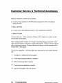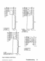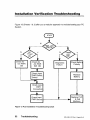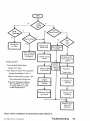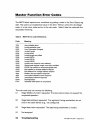
1
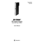
System Planning
and Installation
Guide for Model
PC-E984-3811385
& PC-E984-385D
GM-E984-202
Rev. A
AEG
System Planning
and Installation
Guide for Model
PC-E984-3811385
& PC-E984-385D
GM-E984-202
Rev. A
November, 1992
MODICON, Inc.
One High Street
North Andover, Massachusetts 01845
Preface
This guide describes the PC-E984-381
and PC-E984-385/385D
Programmable
Logic Controller systems together with system planning information and installation procedures.
For brevity and your convenience, the PC-E984-381/385
controller is referred to
in context as the Model 381 E or 385E. Both Model 381 E and 385E are enhanced
with an extra Modbus Port.. The 385D is a 125 VDC version which is otherwise
just like a 385E.
In the context of this manual, the terms “Programmable
Controller” and “Program-
mable Logic Controller” have been abbreviated to “PLC” for brevity. References to
IBM’s personal computer are written out or in context with IBM’s initials.
It is necessary to say that the information in this document is subject to change
without notice and should not be construed as a commitment by MODICON,
Industrial Automation Systems. MODICON,
errors that may appear in this document.
Inc.,
Inc. assumes no responsibility for any
Further, no part of this document may be
reproduced in any form or by any means, electronic or mechanical, without the express written permission of MODICON,
Inc., Industrial Automation Systems. All
rights reserved.
The following are MODICON, Inc. trademarks:
Modicon@
Pi90
984A
984-380
984-381
E984-381
984-385
E984385
D984-385
Micro 984
984
9848
984-480
984x
E984-480
984-885
984-485
E984-885
E984-485
984-780
984-680
984-785
ModbusB
E984-785
984-785L
984-i 20
984-l 30
984-l 45
984-351
984-455
Modsoft@
Modbus Plus
IBM8 is a registered trademark of International Business Machines, Inc.; IBM PC
is a trademark of International Business Machines, Inc.
0 Copyright 1992 Modicon, Inc.
Preface
iii
Objectives
This manual has been written to help you plan, configure, mount, wire, connect,
check out and, if necessary, troubleshoot your PC-E984_381/385/385D
PC sys-
tem. After reading this publication:
A Control Engineer will be able to identify and physically plan the location and
mounting of system components.
A Plant Electrician/Installer will be able to install, power-up and check out the
system.
A Maintenance Technician will be able to recognize, locate, identify and resolve
or report system failures.
How To Use This Manual
Chapter 1 describes the E984-38x
model PC system’s functions.
Chapter 2 offers information for planning your installation with Local I/O.
Chapter 3 is an installation procedure for your controller with local I/O.
Appendix A gives system specifications including a summary table of l/O module
specifications.
Appendix B gives Stopped Error Codes, MODBUS cable connector pinouts, a
table of MODICON 381 E/385E/385D
system end-user part numbers, Customer
Service/Technical Support telephone numbers, and Installation Verification troubleshooting charts.
iv
Preface
Related
Documents
GM-MSFT-001
Modsoft Programmer User Guide
GM-0984-SYS
984 Programmable Controller Systems
Manual
Incoming Inspection Guidelines
Procedure
Step 1
Guidelines for inspection
Before you do anything, verify your shipment is complete and undamaged.
If the shipment is incomplete or
damaged, notify the carrier and your distributor.
Step 2
Remove everything from its packing and check for
physical defects or damage. If the equipment is physically
defective or damaged, notify your MODICON representative.
li7
Note
Save shipping materials until installation is complete.
Sending Something Back?
o To the extent possible, use the original packing materials supplied by
MODICON.
o All equipment should be firmly packed so that it cannot move around in its shipping container.
o All equipment should be protected against impact during shipment.
Preface
v
Table
of Contents
Chapter 1 Controller Introduction
1
.................
E984_381/385/385D Programmable Controller System Description ....
Overview ...............................................
System Features .........................................
System Capacity ........................................
Executive NV RAM .......................................
Executive Functionality ....................................
Module Housings ........................................
Construction ............................................
Power Supply Function (AC and DC) .........................
CommunicationsProcessing Function .........................
Central Processing Unit (CPU) Function .......................
Mainframe Controls ........................................
Mainframe Status Indicators ................................
2
2
3
3
4
4
5
6
7
9
9
10
10
Chapter 2 Planning Controller and IO Installation
13
...
Planning ................................................
Overview ..............................................
Space Requirements .....................................
Primary Power Lines .....................................
Environmental Requirements ...............................
Mounting Hardware Requirements ...........................
Housing Installation Options .................................
Panel or Bulkhead Mounting ...............................
RackMounting ..........................................
Grounding Your Installation ..................................
Primary Power Cable (AC/DC) ..............................
DIP Switch Configurationfor MODBUS, Port 1 ...................
Modbus Port Software Configuration .........................
Modbus Plus Node Address Setting ..........................
Manual Node Address Change .............................
Modbus Plus Bridge Mode .................................
Modbus Plus Node Address Software Change .................
MSTR Format ..........................................
Implementation of Mbus+ Node Address Change via MSTR Block.
vi
Table of Contents
14
14
14
14
15
15
16
16
18
22
22
24
24
27
27
27
28
28
29
Port Delay Timer . . . . . . . . . . . . . . . . . . . . . . . . . . . . . . . . . . . . . . . 30
Chapter 3 Installing Controller and Local I/O
31
........
32
Model 381 E, 385E and 385D Installation Procedure with Local I/O ...
35
Procedure for Installation Checkout - Unconfigured PC ..........
Procedure for Installation Checkout - Configured PC wl Local I/O . . 36
37
Controller to IBM PC Programming Panel Software ............
37
Getting PC into RUN Mode ...............................
39
I/OQuickCheck
.......................................
Appendix A 381 E/385E/385D System Specifications
Mainframe Specifications .................................
Indicators.. ............................................
Circuit Characteristics ....................................
Environmental Characteristics ..............................
Built-in Power Supply ....................................
External Power Issue Specifications .........................
Afipendix B Troubleshooting
. .
41
42
43
43
44
45
45
47
.....................
Stopped Error Codes ......................................
Customer Service & Technical Assistance ......................
Installation Verification Troubleshooting ........................
Master Function Error Codes ................................
Table of Contents
48
50
52
54
vii
Figures
Figure
Figure
Figure
Figure
Figure
Figure
1
2
3
4
5
6
Model 381 E, 385E and 385D Physical Perspective . . . . . .
Model “E’ Controller in Primary Housing AS-H819-209
...
Wiring Connectors, Communications and Memory Switches
H819 Housing Panel or Bulkhead Mounting Dimensions . .
H827 Housing Panel or Bulkhead Mounting Dimensions . .
H819 Rack Mount Dimensions
.....................
... 3
... 6
.. 8
. . 17
. . 18
. . 20
Figure
Figure
Figure
Figure
Figure
Figure
Figure
Figure
Figure
Figure
7 Communication Port Selection Screen . . . . . . . . . . . . . . . . . .
8 View of MEM/DEFAULT communication parameter switch . . .
9 Modbus Plus Node Address DlPs l-6
.. ...............
10 MSTR Block on Modsoft screen With Input/Output Labels . .
11 Typical Local Drop Configuration . . . . . . . . . . . . . . . . . . . . .
12 Configuration Overview Screen . . . . . . . . . . . . . . . . . . . . . . .
13 Traffic Cop Data . . . . . . . . . . . . . . . . . . . . . . . . . . . . . . . . . .
14 Modbus Cable Pinouts . . . . . . . . . . . . . . . . . . . . . . . . . . . .
15 PLC Installation Troubleshooting Chart . . . . . . . . . . . . . . . . .
16 PLC Installation Troubleshooting Chart (Sheet 2) . . . . . . . . .
25
26
27
28
33
38
39
51
52
53
Tables
Table 1
Table 2
Table 3
Table 4
Table 5
.. .
VIII
Memory Per Configuration ............................
Port 1 Configuration ................................
Stopped Error Codes ...............................
Model 381 E/385E and D Controller Part Numbers ........
MSTR Error Code Definations ........................
Table of Contents
4
24
48
49
54
Chapter
1
Controller
Introduction
o This chapter describes your 984, “E” Model 381/385/385D
Programmable Controller system.
GM-E984-202
Rev. A Chapter 1
Controller introduction
1
E984=381/385/385D
Programmable
Controller
System Description
Overview
The Modicon 984 Model 381 E, 385E and 385D Controller is a mid-range Programmable Logic Controller in a modular, expandable, architecture.
It employs
Modicon 800 series housings, interfaces and I/O modules. The Model “E” is supported by the same instruction set as the other 984 Controller models and is programmed by the Modicon Modsoft Programming Panel.
IF
Note
The 385D Model is the same as the 385E except it is the
125VDC version.
Figure 1 is a perspective view of the 381 E/385E and 385D system’s controller
module with built-in power supply. Certain physical features are noted.
2
Controller Introduction
GME984-202
Rev. A Chapter 1
385D
(hidden)
I.IyyLI-
BAmERY
.:
PLUS
MODBUS
PLUS
COVER
Figure 1 Model 381 E, 385E and 385D Physical Perspective
System Features
The Model 381 E/385E/385D
system’s features are described below followed by
somewhat more detailed functional descriptions.
System Capacity
The Model 381 E/385E memory provisions are summarized in Table 1:
GM-E984-202
Rev. A ChaDter 1
Controller
Introduction
3
Table 1 Memory Per Configuration
Local l/O
(ma4
in/out
Controller
Memory
User State
RI/O
Comm
Ports
381 E
385E
16k
16k
0
0
2 Modbus
512/512
1 Modbusand 512/512
1 Modbus+
2k
2k
Discrete
I/O
any mix
in/out
TOTAL
Registers
512
512
2048
2048
385D Same as 385E
The user logic and state RAM support one local drop. This local drop has a maximum I/O module capacity of 21 I/O Modules (19 modules if an auxiliary power
supply is required) and up to 512 discrete points of local I/O (any mix).
Executive NV RAM
The Model “E” controller has it’s bootable memory and executive software downloaded to Non Volatile RAM during the manufacturing process and is not accessible to the user.
Executive Functionalitv
381 E
Executive ID of 813 (Hex), CPU Clock speed 12 Mhz.
24 DX functions:
MOVE (8), MATRIX (8), JSR, RET, LAB, PID2, EMTH, TBLK, BLKT and
CKSM.
Two standard Modbus ports, Time-of-Day
clock, Peer Cop, Local I/O only.
385E
Executive ID of 81C (Hex), CPU Clock speed 12 Mhz.
24 DX functions:
MOVE (8), MATRIX (8), JSR, RET, LAB, PID2, EMTH, TBLK, BLKT and
MSTR.
(MSTR is the user interface to Modbus Plus. It replaces the CKSM function
and uses its opcode.
One Modbus port, One Modbus Plus Port, Time-of-Day
clock, Peer Cop,
Local I/O only.
4
Controller
Introduction
GM-E984-202
Rev. A Chaoter 1
Module Housings
The Model 381 E/385E system uses Modicon 800 series housings for its controller
and I/O modules; specifically, a 19” primary housing with a seven module capacity
or a 27” primary housing with an eleven module capacity.
Primary Enclosure - With the single width Model “E” controller in your primary enclosure, the 19’ and 27” primary enclosures will accommodate up to 6 or IO I/O
modules, respectively.
Secondary Enclosure -The
secondary housing will accommodate a one and one-
half wide P810, P800 or P884 auxiliary power supply if a power supply expander
is required and as many I/O modules as there is room remaining.
Specifically, the standard 19” or 27” secondary housings will accommodate five or
nine I/O modules along with a one and one-half wide (two-slot) auxiliary power
supply and a full seven or eleven I/O modules without the power supply.
The 1g-inch primary housing with controller is shown in Figure 2. For simplicity’s
sake, the 27” housing is not shown in this manual except as required in the illustration on panel mounting dimensions.
GM-E984-202
Rev. A Chapter 1
Controller Introduction
5
SYSTEM BUS CONNECTOR
CAPTIVE SCREWS
UNDER HANDLE
HOUSING
\
984-381 E IN FIRST SLOT ON LEFT
Figure 2 Model “E’ Controller
I
OURBUSCONNECTOR
in Primary Housing AS-H819-209
Construction
The Model “E” controller is housed in a rugged metal chassis designed to withstand specified temperature and humidity extremes as well as vibration, shock,
and ambient atmospheric conditions consistent with the “factory floor.”
The primary housing employs a shielded backplane which provides for internal
communications within the housing. The backplane protects the internal system
communications from both electromagnetic (EMI) and radio frequency interference
(RFI).
6
Controller
Introduction
GME984-202
Rev. A Chapter 1
Captive screws secure all modules in the housings and they should be used to insure good electrical contact between the connector at the rear of the module and
backplane in the housing. Key pin protection is also available.
User memory is backed up by a lithium battery which has a one year service life.
It will hold-up for 14 days after the BAT LOW indicator comes on. The battery’s
installed but unused service life is rated at one year, with a five year shelf life.
A manually operated memory-protect
toggle switch prevents accidental access to
the user’s program. This switch is located on the left side of the unit, above the 3
position communications toggle switch (see Figure 3).
Power Supply Function (AC and DC)
The Model 381 E/385E and 385D system’s controller module comes with a built-in
I/O power supply.
The Model “E” Controllers run on 97 through 276 VAC (47 to 63 Hertz) and 24Vdc.
As shown on Figure 3, Once connected, AC power is then switched ON/OFF with
a front panel rocker switch.
The PLC will also operate continuously on 24Vdc as its an alternate or exclusive
source. Figure 3 shows a primary power input connector for a customer supplied
24Vdc source. Once connected, DC power is then switched ON/OFF with a front
panel rocker switch.
GM-E984-202
Rev. A Chapter I
Controller Introduction
7
Figure 3 Wiring Connectors, Communications and Memory Switches
The 385D input can range from 105 to 150 VDC with the nominal at 125 VDC controlled by a front panel rocker switch. The 24 VDC option is also available.
Note The primary power DC input feature was not designed, nor is it
suitable as an automatic battery backup provision in the event of an AC
outage. This is because the controller’s externally sourced DC input
joins with the AC.sourced, internally produced DC. At any given time,
the Controller is taking from the higher of the two DC voltage sources if
there is as little as a 1V differential. The consequence of this would be
to draw down the DC battery if there were an extended period(s) of reduced AC voltage supply.
8
Controller Introduction
GME984-202
Rev. A Chapter 1
If you want a backup alternative, one could be configured from a user-supplied
DC power supply with its own backup batten and charger combination along with
appropriate monitoring provisions.
Communications Processing Function
The Models 381 E/385E/385D have Modbus capability for data transfer and remote
programming. Through this port, communication processing on the CPU board
can be linked from the controller to supervisory and programming devices such as
a host computer or Modicon programmer.
The Modbus port allows you to sched-
ule one Modbus service per scan. The Model 381 has a second Modbus port
which allows you to incorporate your controller into the Modbus network and still
have a free port for connecting your local programming panel The second port on
the 385E and D is for the Modbus Plus network Connection..
Figure 3 illustrated the controller from the left side. The MEM/DEFAULT/MODEM
toggle switch enables your preset communications configuration for Modbus port
1. (For software configuration, refer to software configurator in Panel software
documentation.)
The DIP switch for setting Modbus Plus port parameters is shown at the bottom of
the illustration but access to the DIP switch is actually through the bottom of the
module’s case.
Central Processing Unit (CPU) Function
The Model “E” uses 24 bit memory architecture and a 16 bit CPU which is fully
compatible with the Modicon 984 PC instruction set, solves user logic at a nominal
rate of 2.5 ms per thousand nodes of user logic. For special applications, a timeof-day clock is provided on all “E” Models.
GM-E984-202
Rev. A Chapter 1
ControllerIntroduction
9
Mainframe
Controls
Mainframe Status Indicators
Status indicators on the CPU module are:
POWER OK
Green LED: When ON, indicates input power OK and voltage outputs OK. Your l/O power OK is indicated by the
READY LED.
READY
Amber LED: When ON, indicates Controller passed powerup diagnostics. Remains ON in Stopped and Run modes
as long as health status is OK. Indicator is OFF when an
error condition is detected by diagnostics.
RUN
Green LED: When ON, indicates Controller is in the RUN
mode and solving logic. If memory checksum fails this light
will blink 3 times for 5 seconds followed by a rest period of
2.5 seconds then the pattern repeats. The controller is in
Kernal mode and needs the executive reloaded.
BATTERY LOW
Red LED: When ON, indicates battery needs to be replaced (14 day holdup from initial indication).
MODBUS Port 1
Green LED: When ON, indicates communication processor
has unit address and communications are in progress.
MODBUS Port 2
Green LED: When ON, indicates communication processor
has unit address and communications are in progress.
(The port 2 indicator is labeled MODBUS PLUS on the 385E and 385D and
indicates status as:)
MODBUS PLUS
Green LED
This LED displays a flashing repetitive pattern to indicate the node status:
NORMAL flashes every 160 msec.
MONITOR NETWORK flashes at one
10
Controller Introduction
GM-E984-202
Rev. A Chapter 1
second intervals. Is in offline state receive only.
NOT RECEIVING
TOKEN flashes two times then is off for
two seconds.
SOLE STATION flashes three times then is off for 1.7 seconds.
DUPLICATE NODE ADDRESS flashes four times then is
off for 1.4 seconds.
mA-FQM--3”3
RPV
A Chanter
1
Controller Introduction
11
Chapter
2
Planning Controller
IO Installation
and
o This chapter describes planning considerations for installing
your PC-E984-381/385
and 385D Controller with local I/O.
GM-E984-202
Rev. A Chapter 2
Planning Controller and IO Installation
13
Planning
Overview
The 381 E/385E and 385D Controller is designed to work with your Modicon Modsoft programming panel; Modicon 800 series housings, interfaces and I/O modules.
The site planner must also consider the peripheral equipment (such as a Programming panel, CRT monitor, or printer) when preparing an installation plan for
the site. Refer to the appropriate Modicon publications for site preparation procedures for related equipment.
Space Requirements
For the primary module housing, allow 12 inch clearance to the left so installer can
see power supply connectors. Allow 6 inches on the top and side of the housing
for convection cooling in vertical mounting situations. Allow 12 inch of clearance
at the bottom of the Controller for cable access.
For all other housings, allow 6 inches on the top and sides of each housing for unobstructed cooling airflow in vertical mounting situations.
Also consider installation and physical access for removal of the modules as well
as subsequent service including the connection and detachment of signal and
power cables when required.
The primary housing may be separated up to 12 feet from the secondary housing
depending only on the on the cable length employed.
Primary Power Lines
In addition to service access, distance to power sources has to be considered in
planning your controller installation. In addition to cable routing considerations,
good practices dictate that the power lines be dedicated to the PC installation to
14
Planning Controllerand IO Installation
GM-E984402
Rev. A Chapter 2
minimize problems that sometimes arise when sharing AC power with electrically
noisy equipment.
Finally, plan to install a service loop and a cable restraint as the primary power
cable as the connector is not locked in place.
Environmental Requirements
In planning for controller installation, consideration should be given to the environment around the controller. Although designed for a harsh industrial environment
and able to withstand factors that would harm other types of electronic equipment,
problems can be avoided by not placing the controller and its related equipment in
an operating area where there is high ambient temperature, acidic atmosphere, vibration, dust, and dirt if it can be avoided.
Mounting Hardware Requirements
After deciding on the final location of the Controller, its associated equipment and
cables, you should plan for related mounting hardware. This would include such
items as: nut and bolt combinations, flat and star washers, housings, mounting
surface, ground straps and system ground connections.
Mounting bolts are NOT provided. The recommended mounting bolts are
0.312-24 UNF-2B (insert or tapped) stainless steel (#8-l 3-SS).
GM-E984-202
Rev. A Chapter 2
Planning Controller and IO Installation
15
Housing
Installation
Options
The 984-381 El385E and 385D system housing can be panel/bulkhead mounted
or rack mounted as described in the following text.
Panel or Bulkhead
Mounting
As shown in Figure 4 below, the H819 housing has keyholes at the top and bottom
of the housing for bulkhead mounting purposes. The keyholes are sized for
5/16-inch bolts. The recommended ground point is also shown.
16
Planning Controller and IO Installation
GM-E984-202
Rev. A Chapter 2
f
225.3
(8.87)
Ul
-L
n
I
n
342.9
(13.5)
_(-
303.3
(11.94)
1.
I!/LliI‘l’
8
ts
cl-
381 E,385E,385D
dR0u~D
T
1
POINT
Figure 4 H819 Housing Panel or Bulkhead Mounting Dimensions
GM-E984-202
Rev. A Chapter 2
Planning Controller and IO Installation
17
225.3
(8.87)
GROUND POINT
Figure 2 H827 Housing Panel or Bulkhead Mounting Dimensions
Rack Mounting
The H819 Module Housings can be mounted in a 19-inch standard (EIA) rack.
Hardware is supplied for installing the “rack adaptor - mounting flange kit” on the
housing but not for installing the adapted housing in the rack.
Figure 3 shows dimensions for rack mounting RI/O housing. The following hardware is required for rack mounting each housing:
0
(1) 1g-inch Standard (EIA) rack
0
(1) pair of rack mounting flanges
18
Planning Controller and IO Installation
GM-E984-202
Rev. A Chapter 2
0
0
(8) #1 O-32, Pan Head Machine Screws to mount the housing to the NEMA
rack
(8) #I O-32 Flat Lock Nuts if mounting holes in racks side rails rails are not
threaded.
0
(8) #8-32 Pan Head Machine Screws (supplied) to attach rack mount
flanges to ends of housing
cl
(8) 114 bolts (supplied) to attach back of rack mount flanges back of housing
GM-E9&?4-202
Rev. A Chapter 2
Planning Controller and IO Installation
19
203
(7.99)
234
(9.22)
L12.7
.
(.50) BOTH SIDES
c
!I
I_
190.5(7.50)
+
6.3
(.25) TYF
1
1
f
Zontroller
5908
GROUND POINT
Figure 6 H819 Rack Mount Dimensions
20
Planning Controller and IO Installation
GM-E984-202
Rev. A Chapter 2
Some planning considerations common to rack mounting for 800 series I/O housings are:
1. Between housings, allow 12 inches below the primary housing for cable breakout, physical inspection and ventilation.
2. The cable length connecting the primary housing and secondary housing must
not exceed 12 feet.
The modular chassis will fit in a 12-inch deep standard NEMA enclosure should
this be required (e.g., an acidic atmosphere in the factory).
Since the only cooling available to the 984 PC is derived from natural convection
air flow. If the PC is placed within a NEMA enclosure, some provision for added
cooling may be required.
GM-E984-202
Rev. A Chapter 2
Planning Controller and IO Installation
21
Grounding
Your lnstallatien
For grounding purposes, Modicon recommends that your 381 E/385E and 385D
PC housing(s) be mounted on a suitably finished metal mounting plate capable of
supporting its weight along with the other modules in the installation. An aluminum
mounting plate with a chromate finish such as IRIDITE, ALODINE or OAKITE
No.36 would meet the requirement. This type of installation provides both a low
frequency (AC) safety ground path and a low impedance shield path for EMVRFI.
If a metal mounting plate (preferred ) is not feasible, Modicon recommends that all
PC housings within a drop be interconnected by a flat braided copper ground strap
with a minimum width of one inch. The ground strap should be kept short and installed without loops and bends. Use stainless steel hardware including a flat
washer to secure the braid strap to the housing.
Regardless of the housing-to-housing
method of ground interconnection, Modicon
recommends the entire installation be grounded by a one inch wide (min) flat,
braided copper strap installed between the the primary housing ground connection
point and a suitable factory ground. The bulkhead and rack mounting illustrations
show the housing’s recommended ground connection point.
Primary Power Cable (AC/DC)
Ideally, the power lines should be dedicated to the PC installation to minimize
problems that arise when sharing AC power with electrically “noisy” equipment.
Provide for strain relief by installing a service loop and cable restraint on the primary power cable as its connector is not locked in place.
AC Power Cable
The recommended AC power cable should consist of three in-
sulated leads of Number 14 AWG stranded copper. The cable leads insert in the
plug-in power cable connector shipped installed in the AC input connector jack
from the factory.
The color code (standard) for the AC cable is white for AC neutral, black for AC
hot, and green for factory or earth ground. The European color code is light blue
instead of white for neutral, brown instead of black for the hot wire, and greenlyellow instead of green for ground.
22
Planning Controllerand IO Installation
GM-E984402
Rev. A Chapter 2
Your AC source cable must be suitable for supplying 115/230 Vat at 5A peak for
the turn-on surge and 0.4A continuous at worst-case, low voltage conditions.
li3=
Note Factory and earth grounds often have different potentials; e.g.,
building steel versus grounding rods.
DC Power Cable
For DC power input, use at least AWG 18.
If you are planning DC backup, note the discussion under “Power Supply Function,” Section 1. Note also, that your external DC input should go directly to the
controller from the power source and not involve your I/O.
Your DC source cable must be suitable for supplying 24Vdc at 24A peak (turn-on
surge) and 1.7A continuous at worst-case, low voltage.
GM-E984202
Rev. A Chapter 2
Planning Controller and IO installation
23
DIP Switch Configuration
Port 1
for MODBUS,
MODBUS Port 1 is both manually and software configurable.
For configuration,
The 3 position MEM/DEFAULT/MODEM
switch on the Left side panel of the controller (behind the handle Figure 8) is used. For software configuration (the MEM
position), use the Modicon programming panel port configuraton software. The
“Default”, “Modem” parameters are:
Table 2
Port 1 Configuration
381 E and 385E
385E Only
MEM
Port 1 CommunicationParameters Taken from
ConfigurationTable
Bridge Mode capable only
if Panel programmed this
option (Default is NO Bridge
Mode
DEFAULT
Port 1 CommunicationParameters are:
RTU, 9600 BAUD, Even Parity, 1 Stop Bit
Address is set on Dip switchunderneath
if 385E or is 1 if 381 E.
Bridge Mode capable
without panel intervention
(i.e. automatic)
MODEM
Port 1 Communication Parameters are:
ASCII, 2400 BAUD, Even Parity, 1 Stop Bit
Address is set on Dip switch underneath
if 385E or is 1 if 381 E
Bridge Mode capable
without panel intervention
(i.e. automatic)
The second modbus port on the 381 E is only set using the programming panel.
Modbus Port Software Configuration
You can use Modicon Modsoft programming panel software to set an internal
memory variable for either Modbus port 1 or port 2 (when the MEM/DIP slide
switch is in MEM). For convenience, a summary of Modsoft screens showing the
communications parameters available is presented here.
From the Main menu you select the “-!-Offline” entry and then select Config from
24
Planning Controller and IO Installation
GM-E984-202
Rev. A Chapter 2
the pulldown selection the results are illustrated in Figure 7. With the cursor on the
Ports selection press the J key to display the pot-l parameter screen.
Segmnts
Loadabl
Cfg
Ext
Quit
l-F2+
:
PLC
Exec Pack
Memory
Extended
Redundant
Memory
OCP Drop
ID
Number
of
TCop
Nwnber
of
Segments
I/O
Drops/Channel
I/O
Modules
Words
Pairs
:
00001
-
01536
Message
Number
Area
Size
of ASCII Ports
1XXXX
10001
30001
-
10512
30048
Simple
Simple
ASCII
ASCII
4xxxx
for
SFC
0xxxx
for
SFC
1Utility
lPLC
OPS
-
Default
Bridae
l-F2-F3-F4
.
Ouit
-F5-Ffi-F7
Mode
Data
Bits
Parity
0
0
Output
Input
-F8-OFF-F9PORTS
Number
32
1
1
Ranges
BXXXX
3xXxX
00015
Stop
Bits
Bridge
Baud
Keyboard
Mode:
Address
Dela!
ODBUS
01
RTU
8
EVEN
1
9600
1
10
02
RTU
8
EVEN
1
9600
1
10
Figure 7 Communication Port Selection Screen
You can fill in the data fields as you require. Pressing the ? key while on a field displays a parameter list for that field.
UT
Note Unsupported Parameters are: 2 stop bits with RTU and parity;
1
stop bit with ASCII and no parity.
GM-E984-202
Rev.A Chapter2
Planning Controller and IO Installation
25
Figure 8 View of MEMlDEFAULT
26
communication
parameter switch
Planning Controller and IO Installation
GM-E984-202
Rev. A Chapter 2
Modbus
Plus
Node Address
Setting
Manual Node Address Change
These node address switches are the first 6 Dip’s seen above, and viewed from
the bottom of the unit. Switches 7 and 8 are not used. Switches One through six
can be set to the binary bit pattern 000000 through 111111which are the equivalent of decimal 0 through 63 respectively. To derive the node address add “I” to
the binary. The default shown in Figure 9 is the binary 0 which is node address I.
To change to an address of 2, place the LSB switch “Toward the number”
(000001)
etc.
Toward number (Open)
Away (Closed = 0)
LSB
Figure 9 Modbus Plus Node Address DIPS l-6
Modbus Plus Bridge Mode
A communications Bridge mode is a standard feature which allows access to thePeer network. Using this mode you can program or monitor any individual node on
the Modbus Pius Network using a program panel connected to modbus port I.
When the Mem / Dip select slide switch is in the MEM position the bridge mode
can be enabled or disabled by using the panel software “Offline” “Configuration”
“PORTS”
Bridge subfunction.
GM-E984-202
Rev. A Chapter 2
Planning Controller and IO installation
27
Modbus Plus Node Address Software Change
The on board dip switches (illustrated above)
are read by the PEER PLC at
power-up to determine what the Node address is. This setting stays in effect until
a power<ycle with new settings or a software controlled “Change Address Command” is issued to the PEER PLC. The Ladder Logic implemented MSTR Block is
the mechanism by which you issue the proper command.
cl3
Note
The Controller in which you want to change the Node address
must be running.
MSTR Format
You can issue the “Change Address Command” using the ladder logic MSTR DX
block. Figure 10 is an example of a Modsoft screen with MSTR block.
&Utility
rFl-
Seg. 5
JPLC Ops JElement JCommand JRef
h
Ladder Diagram
F2F3-F4#I
Active
Error
Complete
Figure 10 MSTR Block on Modsoft screen With Input/Output Labels
o The top node (40100 in the example) defines the first of a nine register block
that contains:
28
4TTTT
Operation Type
FFFF Hex Change Address Command
4TTTT+ 1
Error Status
See Appendix B for Error Codes
Planning Controller and IO Installation
GM-E984-202
Rev. A Chapter 2
4TTl-T+2
Pattern 1
1234 Hex
4TTTT+3
Pattern 2
5678 Hex
4TTTT+4
Pattern 3
XXAA Hex
where xx = 00 for builtin
01 for S985 #I
02 for S985 #2
4TTTT+5
Pattern 4
XXBB Hex
4TTTT+6
4TTTT+7
Pattern 5
Pattern 6
XXCC Hex
XXDD Hex
4TTTT+8
Pattern 7
XXEE Hex
When the Error output passes power, the content of the Error Status register contains an error code to help you determine the cause of the error.
These registers provide a margin of safety against inadvertent change of address.
The values in these seven registers MUST contain exactly the above data or an
error will result.
o The middle node (40200 in the example) contains the new address.
The new address can be a value between 1 and 64.
o The bottom node (a value of 1 in the example) may be set to any value from 1
to 100 but only one address is involved from the middle node.
Implementation of Mbus+ Node Address Change via MSTR Block.
You setup the MSTR block by transitioning the enable input ON for one scan.
The MSTR function Done output passes power in the same scan (assuming no errors). There will be a delay of up to IO seconds in the availability of the newly addressed Controller due to the time required fully implement the change including
reinitialize the link.
If you hold the MSTR block enabled for more than one scan, the Change Address
Command is issued for each scan so enabled. This results in a race condition
locking the controller out of effective operation.
Part of the process of implementing the Change Address Command allows testing
for:
If the specified address equals 0
If the specified address is greater than 64
If the specified address is equal to the current address.
GM-E984-202
Rev. A Chapter 2
Planning
Controller
and IO installation
29
In each true case the PEER Processor ignores the Change Address Request but
remains available to the host processor.
Port Delay Timer
Each Modbus port (one, or two ) can be assigned a time delay value from 10
Miliseconds to 1 second in duration. You use the Modsoft configurator PORTS
menu to do this.
30
Planning Controller and IO Installation
GM-E984-202
Rev. A Chapter 2
Chapter
3
Installing
Controller
Local I/O
and
o This chapter is an installation procedure for your PC-E984-381
385E or 383D with local I/O.
GM-E984-202
Rev. A Chapter 3
installing Controller and Local I/O
31
Model
381 E, 385E and 3851) Installation
Procedure
with Local I/O
Warning
ENSURE THAT YOUR ELECTRICAL SERVICE IS
PROPERLY GROUNDED
AND IN ACCORDANCE
WITH THE ELEC-
TRICAL CODE FOR YOUR AREA. INSTALLATION AND MAINTENANCE SHOULD BE PERFORMED BY A QUALIFIED PERSON IN
CONFORMANCE
WITH LOCAL CODE AND THE NATIONAL ELEC-
TRICAL CODE. ANSI/NFPA PUBLICATION NO. 70.
Procedure
Step 1
Installation
Install cable troughs in your primary and secondary housings in accordance with the local drop, I/O module assignments planned.
Step 2
Step 3
Mount housings for local drop on desired surface taking
care to observe system ground requirements.
Connect power and signal cable between primary and secondary housings as required by your configuration. See
example shown in Figure 11.
32
Installing Controller and Local l/O
GME984-202
Rev. A Chapter 3
381 E
I/O
I/O
110
I/O
110
1
l/O
RACK #
I/O
RACK # 2
Rack Interconnect Cable (WBOI)
Auxiliary Power Cable (W804)
PBIO
Power
SUPPlY
I/O
I/O
I/O
I/O
Figure 11 Typical Local Drop Configuration
Step 4
Ground power cable’s ground strap to system ground on
housing (shown in Chapter 2).
Step 5
Set MEM - DEFAULT - MODEM communication select
switch for MODBUS Port 1 as desired. (Default position
assumed during installation checkout).
Step 6
Verify presence of memory backup battery.
If lithium battery has been supplied separately, install in battery compartment observing polarity marked inside battery
compartment cover.
lw
Note
When removing battery, push to compress loading spring which
will partially eject battery as you let go.
GM-E984-202
Rev. A Chapter 3
Installing Controller and Local I/O
33
Install 381 E or 385E/D controller module in Slot 1 of prima-
Step 7
ry housing, securing with captive screws.
Set memory protect switch to OFF.
Step 8
If using an auxiliary power supply, partially insert it in Slot 1
Step 9
of expansion housing.
IN STEPS 10 THRU 19 BELOW, THE AC AND DC PRIWarning
MARY SOURCES SHOULD NOT BE CONNECTED (ENERGIZED)
ON THE SOURCE SIDE.
Wire auxiliary power supply input power, and then secure
Step IO
module in housing.
Step 11
Wire AC primary power cable to controller’s AC input power
connector shown in Chapter 1 Figure 3
Form service loop in AC input power cable and install me-
Step 12
chanical restraint on housing.
Plug AC input power cable connector into controller’s AC
Step 13
input power jack at left side of module. DO NOT CONNECT TO PRIMARY POWER SOURCE AT THIS TIME!
If using DC input, wire to controller’s DC input connector.
Step 14
Form service loop in DC input power cord and install me-
Step 15
chanical restraint on housing.
Step 16
Plug DC input power cable connector into controller’s DC
input power jack on left side of controller. DO NOT CONNECT TO PRIMARY POWER SOURCE AT THIS TIME!
Step 17
Step 18
Do field wiring for local drop and attach to I/O connectors.
Install key pins in I/O housing slots (as required in your installation plan).
34
Installing
Controller
and Local
I/O
GM-E984-202
Rev. A Chapter 3
Step 19
UT
Note
Verify ground and cable connections are secure and according to plan.
Other than local I/O, the physical installation of your Model “E”
Controller is now complete.
You are ready for initial power-up and in-
stallation check-out.
Procedure for Installation Checkout - Unconfigured PC
Step 1
If using DC input power, energize DC power source and
switch controller’s DC power switch to ON.
If not using DC input, go to Step 4 below.
Step 2
Visually inspect installation and verify operation. After a
few seconds of delay for internal diagnostics, your Model
381 E/385E (or D) POWER OK indicator should come up
Green and the READY indicator, Amber. The BATTERY
LOW indicator should be OFF.
Note
If you have an obvious mechanical or electrical problem, take
the appropriate corrective action.
If your LED status seems incorrect, try to eliminate the possibility of a
false indication resulting from parallax error (one LED lighting more
than one indicator window).
If your LED status is incorrect, refer to the
Installation Troubleshooting Chart, Figure B-2.
If all else fails, call us at the number listed under technical assistance,
Appendix B.
Step 3
GM-E984-202
Rev. A Chapter 3
Switch controller’s DC input power switch to OFF.
Installing
Controller
and Local I/O
35
Step 4
Step 5
Connect primary power input to AC source and set controller’s AC power switch to ON.
Visually inspect installation and verify operation.
After a
few seconds of delay for internal diagnostics, your Model
“E” Controller POWER OK indicator should come up Green
and the READY indicator, Amber. The BAl7ERY
LOW in-
dicator should be OFF.
lw
Note
If you see the RUN light blink 3 times followed by a slightly
longer off period, the checksum diagnostic failed and the Kernal mode
is entered. Notify your systems programmer. You have to download the
executive to continue.
If your LED status seems incorrect, try to eliminate the possibility of a
false indication resulting from parallax error (one LED lighting more
than one indicator window). If your LED status is incorrect, refer to the
Installation Troubleshooting Chart in Appendix B.
Note
If you have an obvious mechanical or electrical problem of any
nature, take the appropriate corrective action.
If your LED status seems incorrect, try to eliminate the possibility of a
false indication resulting from parallax error (one LED lighting more
than one indicator window). If your LED status is incorrect, refer to the
Installation Troubleshooting Chart, Figure B-2.
If all else fails, call us at the number listed under technical assistance,
Appendix B.
Procedure for Installation
I/O
ET
Note
Checkout
- Configured
PC w/ Local
Record Executive ID and the version number from The panel
software Status Screen.
36
installing Controller and Local I/O
GM-ES&&202
Rev. A Chapter 3
Finish your installation verification by configuring and Traffic Copping your PC and
then communicating with local I/O.
Step 1
Set your controller’s input power to OFF. Shut off auxiliary
power.
Step 2
Install a simple I/O module in Slot 2 of primary housing (a
B805 for example) and secure with captive screws.
Step 3
Repower
Controller to IBM PC Programming Panel Software
Step 4
Connect Controller MODBUS, Port 1 to panel Serial Port
using W955 cable with 25 to 9 pin converter or W956 9 to 9
pin cable and power-up the panel.
Step 5
At your DOS prompt type CD\Modsoft then at the MODSOFT directory prompt type MODSOFT to execute the
panel software.
69
Expert Step 5 assumes
your panel software is available in your computer. If it is not refer to the Modsoft Programmer User Manual GMMSFT-001
for the load procedure.
Getting PC into RUN Mode
A new controller can not be RUN without providing some data about the configuration in which it is to operate. Steps 6 through 11 provide a quick method to assure
that your new controller will RUN.
Step 6
Step 7
Press the panel “Enter” key ( J ) to display the main menu.
You can either download pre-existing configuration data
using the Filer or initialize a configuration by selecting
“Config” from the the LOffline menu entry.
GM-E984-202
Rev. A Chapter 3
installing
Controller
and Local I/O
37
You will see the configuration overview screen as illustrated
in Figure 12. The Menu selections allow you to select the
Step 8
information that defines your PLC configuration.
Return to the main menu and select “Login” From the
Step 9
JPLC Ops Menu. If the cable and PLC are ok You will see
the modbus LED Flash.
Step 10
Return to the main menu select the LRV entry and Select
JLRV Options of “Configuration” and No State. You will see
the screen display the configuration word length and the
Modbus Pot-t flashes during the transfer.
If you now return to the Main menu &PLC Ops and select
Step 11
the “Start” function and then follow that up with a “Y” to the
screen prompt, the controller will start and the Green RUN
LED is lighted.
]rU;T;;C
Ops
Segmnts
Loadabl
l;;rView
Ports
TCop
F6-F7-FE-OFF-F9-F4-F5CONFIGURATION
OVERVIEW
Size
:
PLC
PLC Type
Exec
of
Number
964
-
361E
Pack
Memory
Redundant
DCP Drop
ID
Logic
TCop
:
16.0K
K
I/O
I/O
1
Modules
ASCII
:
Number
of
Messages
BXXXX
00001
-
01536
Number
of
lxxxx
10001
-
10512
Simple
ASCII Output
3xxxx
30001
30046
41672
ASCII
40001
for
SFC
-
Simple
4xxxx
4xxxx
Message
Battery
SFC
None
Prea
Timer
Size
ASCII
6E0
0
0
Ports
0
Input
:
Specials
SKIP
for
15396
32
1
:
Bxxxx
Quit
00015
I/O
Type
Number of Segments
I/O
Orops/Channel
Pairs
Ranges
None
Area
Words
Ext
-
984
Memory
Extended
Full
of
Cfg
Functions
Coil
Register
Y
0--_-4-----
I.
Figure 12 Configuration Overview Screen
38
Installing Controller and Local l/O
GM-E984-202
Rev. AChapter
I/O Quick Check
To check the I/O side of your configuration, assuming you have a 8805 and B804
in slot 3 and 4 respectively. Proceed to add the Traffic Cop information for these
two modules to the configuration data you already established by:
Step 12
Return to the panel Configuration screen and enter the
number of I/O modules as the value 2.
Step 13
Go to the Config screen TCop function and define the presence of the two modules. Figure 13 is an example of what
the data looks like.
SUtility
1PLC
Ops
DelDrop
HoldTme
ASCPort
JGetDrop
Special
Quit
rFi-F2-F3-F4-FS-F6-F7-F8-OFF-F9TRAFFIC
800
Drop
Drop
:
Hold
Number
Up Time
Inputs
:
:
Module
Slot
1EI
984
6805
103
8804
105
104
106
187
108
109
110
111
ii
88
88
68
B8
88
88
SERIES
of1
(xI00ms)
3
I/O
Rack
16
ASCII
Number
Reference
Input
Type
102
I
COP
Numbers
I
Port
E
Outputs
Data
output
type
i
16
Module
Description
PLC-381E
10001
-10016
00001
-00016
E-IN
16-OUT
6885
6804
Figure 13 Traffic Cop Data
Step 14
Return to the main menu and select the .iPLC Ops menu
“Stop” function. Respond to the screen prompt with “Y” and
watch the RUN LED go off.
Step 15
You now repeat the earlier steps (step IO) to download the
configuration but this time the traffic cop data is downloaded with it.
GM-E984-202
Rev A Chapter3
Installing
Controller
and Local I/O
39
Step 16
Use the &PLC Ops menu to Restart the controller.
Step 17
Visually inspect installation and verify operation. The Green
POWER OK indicator and Amber READY indicator status
should remain ON. The RUN indicator should be Green.
Your I/O module ACTIVE indicators should be Green.
Note Your PC installation is now complete and verified. If you have
an obvious problem, take the appropriate corrective action. If your
LED status is incorrect, refer to the Installation Troubleshooting Chart
40
Installing
Controller
and Local I/O
GM-ES&&202
Rev. A Chapter 3
Appendix
A
381 E/385E/385D
Specifications
System
o This appendix covers the following specifications:
o PHYSICAL CHARACTERISTICS
Dimensions
Weight
o ELECTRICAL CHARACTERISTICS
Static Discharge Agency Approval
Magnetic
Indicators
o CIRCUIT CHARACTERISTICS
Scan Rate
Memory
Throughput
Holdup
Power Consumption
I/O
Surge Withstand Time-of-Day Clock
GM-E984-202
Rev. A Appendix A
381 E/385E/385D System Specifications
41
o ENVIRONMENTAL
CHARACTERISTICS
Temperature
Humidity
Max Wet Bulb
Altitude
Shock
Vibration
o BUILT-IN POWER SUPPLY
Holdup
Fusing
Indicators
Output Power
Output Voltage
Input Power
IJ EXTERNAL POWER ISSUES
AC Isolation Transformer
External 24Vdc Power Supply
800 Series I/O Module Loading
Mainframe Specifications
Physical Characteristics
Dimensions
WxHxD inch
WxHxD (mm)
2.54 x 10.5 x 8
(39.4 x 266 x 203)
Weight = 5 Ibs, 1 oz
Electrical Characteristics
Static Discharge
15kV to all surfaces
Magnetic
20 Gauss field inside Helmholtz Coil, 0.25 to 8 pps
Agency Approval
Designed to meet applicable agency safety
requirements
42
381
E/385E/385DSystem
Specifications
GM-E986202
Rev. A Appendix A
Indicators
o POWER OK
Green LED: When ON, indicates input power OK and voltage
outputs OK. Your I/O power OK is indicated by READY LED.)
Amber LED: When ON, indicates Controller passed power-up
o READY
diagnostics. Remains ON in Stopped and Run mode as long as
health status is OK. Indicator is OFF when an error condition is
detected by diagnostics.
Green LED: When ON, indicates Controller is in the RUN mode
o RUN
and solving logic. If memory checksum fails this light will blink 3
times for 5 seconds followed by a rest period of 2.5 seconds
then the pattern repeats. The controller is in Kernal mode and
needs the executive reloaded.
o BATTERY LOW
Red LED: When ON, indicates battery needs to be replaced
(14 day holdup from initial indication).
o MODBUS
PORT 1
0
MODBUS
PORT 2
ET
Green LED: When ON, indicates communication processor has
unit address and communications are in progress.
Green LED: When ON, indicates communication processor has
unit address and communications are in progress.
Note There are two Modbus ports on the 381 E only. The 385E and
385D have one Modbus and One Modbus Plus Port.
Circuit Characteristics
o Scan Rate
2.5 ms per thousand nodes of user logic
o Throughput
c15ms for 64 I/O points
I/O
512 discrete points any mix maximum configuration
1024 register points 512 in/51 2 out
Max I/O Modules in drop = 21
GM-E984-202
Rev. A Appendix A
381 E1385E1385DSystem Specifications
43
Memory Capacity User Logic Registers Option
1920 State RAM
16 K Words User Logic
Holdup
32ms for CPU from “POWER OK” going inactive
Surge Withstand
Per IEEE 472-1974,
ANSI C37.90a
Model 381 E
Time-of-Day
Clock f 1 set/day @ 25C
+ 3 seclday, 0-4OC
+ 8 seclday, 0-6OC
Environmental Characteristics
Temperature
Operating: 0 --> 60C
Storage: -40 -> +8OC
Humidity
O-95% Non-condensing
Max Wet Bulb
Non-operating: Non-condensing
Operating: 85F
Altitude
10,000 feet max
Shock
+ 1Og’s, 11 ms, 3 pulses per axis
Vibration (Operating)
5Hz to 50Hz @ .005 in D.A.,
30 min/axis
50Hz to 500Hz @ 0.625 g’s, 30 min/axis
Vibration (Non-operating)
1OHz to 50Hz @ .029 g’s/Hz
50Hz to 300Hz @ .029 g’s/Hz,
-8dBloctave
44
381
E/385E/385D System Specifications
GM-E984-202
Rev. A Appendix A
Built-in Power Supply
Input Power 115 Vat f 15% 47-63 Hz
230 Vat ?I 15 % 47-63
Hz
24 Vdc f 15% Isolated source (24~ @ 3A)
125 VDC f. 15% Isolated source (105~ @ .295A, 125~ @ .248A)
Maximum inrush current surge 6.44A.
Fuses
0.750A, 3A SB Buss, Not customer replaceable
Holdup
32ms for CPU from Power OK going inactive
Steady State
Power Consumption
Current
5W
.42A@
12OVac
Indicators
Green LED: POWER OK
output to I/O
18.75 Watts to I/O service
output*
VI
5Vdc I/O
V2 4.3Vdc I/O
3.5A max
3.5A max
External Power Issue Specifications
Isolation
1OOW (recommended) based on
Transformer
40.8W (meas) and assuming 0.4A continuous (w/97Vac
115V I!I 15%), 5A peak
Ext 24Vdc P.S.
31 W nom, 1.3A dc continuous @ 24Vdc (24A peak); or
1.7A de cant @ 20.4Vdc (24V -15%)
GM-E9&34-202
Rev. A Appendix A
381 E/385E/385D
System Specifications
45
Appendix
B
Tksubleshooting
o This appendix contains troubleshooting help and Modicon telephone numbers for Customer Service and Technical Support.
Modbus cable pinouts are illustrated for troubleshooting purposes. An installation verification troubleshooting chart is illustrated on two sheets.
GM-E984-202
Rev A. Appendix B
Troubleshooting
47
Stopped
Error Codes
Table 3 lists all stopped error codes applicable to 984 family controllers.
Table 3
Stopped ErrorCodes
Machine Stop Bits
PCSICK
PCSTOPPED
BADTCOP
DIMAWAR
PORTIVENT
BADSEGSCH
SONNOTIST
PDCHEKSUM
NOEOLDOIO
RTCFAILED
BADOXUSED
RIOFAILED
NODETYPE
ULCSUMERR
DSCRDISAB
BADCONFIG
Ox7FFF
0x8000
0x4000
0x2000
0x1000
0x0800
0x0400
0x0200
0x0080
0x0040
0x0020
0x0010
0x0008
0x0004
0x0002
0x0001
Description
Controller unhealthy
Controller stopped
Bad I/O traffic cop
PC in dim awareness
Bad port intervention
Bad segment scheduler
Son did not start segment
Bad power-down checksum
Watchdog expired
Real time clock failed
Bad coil used table
Remote IO option failed
Illegal node type user
User logic checksum error
Discretes disable error
Bad configuration
Table 4 shows MODICON 984-381/[385]
48
Troubleshooting
system end-user part numbers.
GME984-202
Rev A. Appendix B
Table 4
Model 381 E1385E and D Controller - End-User Part Numbers
Description
Part Number
/-/oushgs
AS-H81 9-209
AS-H827-209
AS-H81 9-l 00
AS-H827-100
Primary 19” Housing
Primary 27” Housing
Secondary 19” Housing
Secondary 27” Housing
Cables
AS-W954-006
AS-W955-012
AS-W955-025
AS-W956-012
AS-W956-025
AS-W953-006
AS-W953-012
AS-W9531025
AS-W801-Oxx
AS-W802-Oxx
AS-W804-Oxx
AS-W808-oxx
Modem to 984-x80
IBM PC/XT to 984-x80
IBM PC/XT to 984-x80
IBM PC/AT to 984-x80
IBM PC/AT to 984-x80
P190 to 984-x80
P190 to 984-x80
P190 to 984-x80
Housing interconnect signal cable
Housing interconnect power cable
Housing interconnect aux power cable
Housing interconnect power cable
Software
Modsoft
SW-MS1 D-9SA Revision 1.2 is required
GM-E984-202
Rev A. Amendix
8.
Troubleshooting
49
Customer
Service
& Technical
Assistance
Modicon telephone numbers are as follows:
D To call us from anywhere in North America except from within the state of
Massachusetts:
l-(800)-468-5342
o To call us from within Massachusetts or from outside North America:
i-(508)-975-5001
Customer Service - When calling the Modicon 5001 telephone number, ask for
service from the list below.
When calling the 800 number, you will get a recording asking you to enter a one
digit code for the type of service you want (listed below). However, this only works
with a “touch tone” phone. If using a dial phone, hang on and the operator will intercept after a short pause.
The service categories - and extra digit code responses for push-button phones are:
“1” - Hardware or software technical support
“2” - Order entry, buying hardware or software
“3” - Return/exchange status inquiries
“4” - Training/course registration inquiries
“5” - General information other than above.
50
Troubleshooting
GME984-202
Rev A. Appendix 6.
NC. 1 ii&----~
1 GND
GND 1 p’-+----:
Rx02
PTXD
.RXDP
TxD3
3m
GND 5
4 FITS
DTR4
DTR4
5 CTS
GND 5
DSR 6
M
‘ D3
DSR 6
-.
GDSR
RTS 7
a
7GND
RTS 7
6
CTS 6
CTSB
, GND
NC. 9
NC. 9
10
11
12
13
NC
14
15
16
17
16
19
91
A. E904 Modbus
to P190
(AS-W953-000)
4
!I 25
Pi
GNDl.
RXDP.
I_.
B. E984
Modbus Connector
To Modem
(AS-WSSS-000)
20DTR
A
TXDB.
NC.
p3
.
1 GND
l
2TXD
.
3RY.D
Pi
GND 1
PODTR
N.C.
21 25
P3
N.C. 1 CD
PRXD
RXDP
NC. 9
TxD3
3TXD
DlR4
4DTR
GND 5
DSR 6
5 GND
@
6 DSR
RTS 7
7 RTS
CTS 6
6 CTS
NC. 9
N.C. 9 R 1
D. E984 Modbus
to IBM AT
(AS-W956-000)
C. E984
Modbus Connector to
Null Modem (IBM PC/XT)
N.C.
Figure 14 Modbus Cable Pinouts
GME984-202
Rev A. Appendix 8.
Troubleshooting
51
Installation
Verification
Troubleshooting
Figure 15 (Sheets 1 & 2) offer you a modular approach to troubleshooting your PC
System.
N
I
ON
SW ON
1
-T-z
Figure 15 PLC Installation
52
Troubleshooting
Troubleshooting
l-Y
Chart
GME984-202
Rev A. Appendix 8.
or Path
Procedure
Check Comm
STOP / START
From Modsoft Main Menu:
Select “PLC Ops”
Pick “Stop (or Start)” from pulldown
Answer the display ? with “Y”
Return to Main Menu select “LRV”
Then download Config Files
If System Message indicates
“NO CONFIG” use “Filer”
or config editor to create
a valid configuration
Figure 16 PLC Installation Troubleshooting
GM-E984-202
Rev A. Appendix B.
Chart (Sheet 2)
Troubleshooting
53
Master
Function
Error Codes
The MSTR block reports error conditions by putting a code in the Error Starus register. The code is a hexadecimal value in the form: “Mmss” where M is the Major
code, m is the minor code and ss is the sub-code.
Table 5 lists the code with the
associated meaning.
Table 5
MSTR Error Code Definations
Meaning
1001
2001
2002
2003
2004
2005
2006
2007
2008
2009
200A
2008
2ooc
2000
3oss
4001
5001
6mss
FOOI
User initiatedabort
Invalidoperation type
User Parameter changed
Invalid Length
Invalid offset
Invalidlength and offset
Invalid SDDA
Invalid SDNA
Invalid SDNR
invalid route (equal to own address)
Global read request length more than available
PEER Cop conflicton write/read global data
Bad pattern for change addressrequest
Bad address for change addressrequest
Modbusslave exceptionresponse
InconsistentModbus slave response
Inconsistentnetwork response
Routingfailure
Selected 5965 optionis not present
The sub-code (ss) can convey the following:
01
Illegal Modbus function requested. The slave device does not support the
requested operation.
02
illegal data address requested. The register(s) being read/written do not
exist in the slave device (e.g., not configured).
03
Illegal data value requested. The
‘
data being read/written is invalid.
04
Not assigned
54
Troubleshooting
GM-E9fJ4-202
Rev A. Appendix 8.
05
06
Slave has accepted long duration program command (does not apply).
Function requested cannot be performed at this time because a long
duration program command is in process.
07
Slave has rejected long duration program command
The m field indicator provides an index into the routing information and indicates at
which device the failure was detected. A value of 0 indicates the local device. a 1
is routing 1, 2 is routing 2 etc.
GM-E984-202
Rev A. Appendix 8.
Troubleshooting
55
Index
B
L
Battery, 7
Bridge Mode, 27
Local I/O, 32
M
C
Comm Port Timing, 30
Communication Ports, 43
Communications Cable, 37
Configuration Select Switch, 24
Cooling, 21
CPU Stopped Error Codes, 48
D
DC Power, 23
Diagnostics, 36
P
E
Equipment Housing, 5
G
Grounding, 16, 22,23,32
H
Housing Clearance, 14
Power OK, 35
Primary Housing, 6
Primary Power, 14,22
R
R I/O Housing, 18
Run Mode, 37
S
I
indicators, 43
Software ID, 36
T
K
Kernal Mode, 10
Key Pins, 34
GM-0984402
Memory Protect Switch, 34
Modbus, 9
Modbus Pius, 9, 10
Modbus Plus Address, 28
Modbus Plus Address DIP, 27
Model E Controller, 2
Modicon Assistance, 50
Modsoft, 2,37
Mounting bolts, 15
MSTR Block, 28
MSTR Block Errors, 54
Rev. A
Traffic Cop, 39
Troubleshooting, 35, 52
Index
57
Modicon, Inc., Industrial Automation Systems
One High Street, North Andover, MA 01645
(506) 794-0600
24 Hour Support Center l-800-468-5342
PM ~/CIA NP
Printed I” U.S.A