1
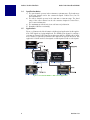
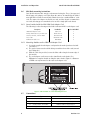
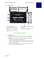
Model 2824
Broadband WDM
IOM2824
Revision 1.0, August 2004
Instructions for Installation and Use
Read this manual before installing or using this product.
Observe all safety warnings and cautions.
Copyright © 2004 by Force, Incorporated. All rights reserved. Force, Incorporated reserves the right to make changes
to the product described in this document in the interest of document improvement.
825 Park Street Christiansburg, VA 24073 • TEL (540) 382-0462 • FAX (540) 381-0392 • USA (800) 732-5252 • [email protected] • www.forceinc.com
Model 2824 Broadband WDM
Preface
WARNING
The optical emissions from the optical connectors and the optical fiber
are laser-based and may present eye hazards. Follow all safety precautions.
About this Manual
This manual explains how to configure and install the Model 2824 Broadband
WDM. It is intended for engineers and technicians who will install the Model 2824
units. While this guide provides basic information on how to configure and install
the units, it assumes that you as the user are familiar with:
• the installation and manipulation of electronic and fiber optic transport equipment
• the installation and manipulation of wavelength-division multiplexers
This manual is divided into the following sections:
• Section 1, page 1, Product TB: Describes the Model 2824, lists technical specifications, system applications, and ordering information.
• Section 2, page 5, Installation and Operation: Describes the installation, operation and troubleshooting of the Model 2824 and its connections to companion
optical transport equipment.
• Section 3, page 9, Maintenance and Safety Precautions: Describes unit maintenance and all relevant safety precautions.
A quick-reference index completes the user manual.
Revision 1.0
ii
Model 2824 Broadband WDM
Preface
Related Documentation
• IOM2981 3RU Rack Chassis and Rack Adapter Cards
• Fiber Optic Reference Guide, 3rd Edition. by David R. Goff (Focal Press 2002):
General theory and operation of fiber optic units.
• Web Site: Our web site, http://www.forceinc.com may be used to download the
latest versions of this manual.
Technical Support
If you encounter any kind of problem after reading this manual, contact your local
distributor or a Force, Inc. Applications Engineer. To reach technical support:
On the Web:
By Phone (Monday through Friday 8:00 am
to 5:00 pm EST):
By Fax:
By Email:
http://www.forceinc.com
USA (800) 732-5252
TEL (540) 382-0462
(540) 381-0392
[email protected]
Warranty
Force, Incorporated standard products are warranted to be free from defects in
materials and workmanship, meeting or exceeding factory specified performance
standards for a period of three (3) years from date of purchase.
Force Obligations
Force will, at its discretion and expense, repair any defect in materials or workmanship or replace the product with a new product. Force will, upon receipt of
the return, evaluate the product and communicate to the customer the nature of
the problem, and determine if the claim falls under warranty coverage.
If during the warranty period, Force is unable to repair the product to the original
warranted state within a reasonable time, or if subcomponents of the unit have
been obsoleted or discontinued, then Force has the option to provide an equivalent unit.
Exclusions
This warranty does not extend to any product that has been damaged due to acts
of God, accident, misuse, abuse, neglect, improper system design or application,
improper installation, improper operation or maintenance, or connection to an
improper voltage supply.
The Force warranty does not cover fuses, batteries, and lamps. Modifications or
alterations of Force products (including but not limited to installation of non-Force
equipment or computer programs), except as authorized by Force, will void this
warranty. Removal or breaking of the seals on the product will also void the warranty. In addition, cost of repair by unauthorized persons within the warranty
period of the product will not be covered by Force, Incorporated. Such repairs
will void the warranty.
Revision 1.0
iii
Preface
Model 2824 Broadband WDM
Force, Incorporated makes no other representation or warranty of any other kind,
express or implied, with respect to the goods, whether as to merchantability, fitness for a particular purpose, or any other matter. Force, Incorporated’s liability
shall not include liability for any special, indirect or consequential damages, or for
any damages arising from or attributable to loss of use, loss of data, loss of goodwill, or loss of anticipated or actual revenue or profit, or failure to realize expected
savings, even if Force, Incorporated has been advised of the possibility of such
damages. This warranty constitutes Force, Incorporated’s entire liability and the
customer’s sole remedy for defects in material and workmanship.
iv
Revision 1.0
Model 2824 Broadband WDM
Contents
Contents
Preface................................................................................................................. ii
Section 1 Product Technical Bulletin..................................................................... 1
1.1 Product Overview................................................................................................................1
1.2 Optical Specifications...........................................................................................................1
1.3 Environmental and Physical Characteristics...........................................................................1
1.4 Specification Notes ..............................................................................................................2
1.5 Applications .........................................................................................................................2
Figure 1.1 Broadband WDM in a Bidirectional Application.............................................2
Figure 1.2 Broadband WDM in a Unidirectional Application ..........................................3
1.6 Part Numbers.......................................................................................................................3
Section 2 Installation and Operation .................................................................... 5
2.1 General Installation Requirements........................................................................................5
2.2 Items Provided.....................................................................................................................5
2.3 Items Required.....................................................................................................................5
2.4 Inspection ............................................................................................................................5
2.5 Stand-alone Module Installation ..........................................................................................5
2.6 3RU Rack-mounting Instructions..........................................................................................6
2.6.1 Items Provided with the 2981 3RU Rack Adapter Card ........................................ 6
2.6.2 Mounting Modules on the 3RU Rack Adapter Card ............................................. 6
Figure 2.1 Model 2824 on a 2981 Rack Adapter Card...................................................6
2.7 Connections.........................................................................................................................6
2.8 Unit Description...................................................................................................................7
Figure 2.2 Model 2824 Broadband WDM .....................................................................7
2.9 Initial Power-up ...................................................................................................................7
2.10 Troubleshooting.................................................................................................................8
Revision 1.0
1
Contents
Model 2824 Broadband WDM
Section 3 Maintenance and Safety Precautions .................................................... 9
3.1 Unit Maintenance ................................................................................................................9
3.2 Cleaning ..............................................................................................................................9
3.2.1 Optical Connector Cleaning Equipment ............................................................. 9
3.2.2 Directions for Optical Connector Cleaning ......................................................... 9
3.2.3 Connector Handling ....................................................................................... 10
3.3 Safety Precautions..............................................................................................................10
3.3.1 Laser Safety Procedures................................................................................... 10
3.4 Shipping and Handling Precautions ....................................................................................11
3.5 Storing the Unit .................................................................................................................11
3.6 Repair Service ....................................................................................................................11
Index ................................................................................................................. 13
2
Revision 1.0
Model 2824 Broadband WDM
Section 1 Product
Technical Bulletin
1.1
Product Overview
The Force, Incorporated Model 2824 Broadband WDM allows a single fiber to be
used to simultaneously transmit two optical signals of different wavelengths. The
WDM at the transmit end combines a signal in the 1260-1360 nm range and a signal in the 1460-1620 nm range for output onto a single fiber. The WDM at the
receive end separates the two signals onto two output fibers with minimal
crosstalk and low loss. Over one fiber, the Model 2824 can transmit either dual
unidirectional data or video, bidirectional data or video, or video and pan-tiltzoom control The broadband range of this product makes it ideal for CWDM systems, broadband networks, and EDFA applications.
1.2
Optical Specifications: @25°C, Single-mode Fiber
Pass Channel Wavelength
Reflect Channel Wavelength
Optical Input Power
Pass Channel Insertion Loss
Reflect Channel Insertion Loss
Pass Channel Isolation
Reflect Channel Isolation
Polarization Dependent Loss
Return Loss
Directivity
Thermal Stability
1.3
Min.
Typ.
Max.
Units
1260
1460
1310
1550
28
13
0.6
0.45
30
15
1360
1620
+22
0.8
0.6
0.004
nm
nm
dBm
dB
dB
dB
dB
dB
dB
dB
dB/°C
Max.
Units
+75
+85
95
°C
°C
%
oz.
g
in.
mm
0.1
50
55
Notes
See Section 1.4
1
2
1, 3
2
1
2
Environmental and Physical Characteristics
Min.
Operating Temperature Range
Storage Temperature Range
Humidity
Weight
Physical Dimensions
Revision 1.0
-40
-40
5
Typ.
8.3
235
5.75 x 3.16 x 0.78
146 x 80 x 20
Notes
See Section 1.4
4
1
Product Technical Bulletin
1.4
Model 2824 Broadband WDM
Specification Notes
1) The pass channel operates in the 1260 nm to 1360 nm range. The band range
of the pass channel can be also customer designed. Contact Force, Inc. for
more information.
2) The reflect channel operates in the 1460 nm to 1620 nm range. The band
range of the reflect channel can be also customer designed. Contact Force,
Inc. for more information.
3) The maximum specification is given at all states of polarization.
4) Humidity is RH non-condensing.
1.5
Applications
Figure 1.1 illustrates the Model 2824 in a bidirectional application. In this application, CATV signals are being multiplexed. The WDM’s pass channel is carrying a
1310 nm 10 Channel CATV signal in one direction while the WDM’s reflect channel is carrying a 1550 nm 25 Channel CATV signal in the opposite direction. This
application could be used for data signals or audio signals as well as video signals.
Figure 1.1 Broadband WDM in a Bidirectional Application
2
Revision 1.0
Model 2824 Broadband WDM
Product Technical Bulletin
Figure 1.2 illustrates a unidirectional application for the Model 2824. Again, the
signals are CATV signal in the 1310 nm and 1550 nm range, but any signal type
could be used.
Figure 1.2 Broadband WDM in a Unidirectional Application
1.6
Part Numbers
Part Number
Description
2824WC-SFSC
Broadband Wavelength-division Mux/Demux, Single-mode,
1310/1550 nm, SC/PC Connector
2824WC-SFFC
Broadband Wavelength-division Mux/Demux, Single-mode,
1310/1550 nm, FC/PC Connector
2824WC-SFAP
Broadband Wavelength-division Mux/Demux, Single-mode,
1310/1550 nm, FC/APC Connector
2824WC-SFST
Broadband Wavelength-division Mux/Demux, Single-mode,
1310/1550 nm, STTM Connector
Revision 1.0
3
Product Technical Bulletin
Model 2824 Broadband WDM
Notes:
4
Revision 1.0
Model 2824 Broadband WDM
Section 2 Installation
and Operation
2.1
General Installation Requirements
The installation of these units is very simple. There are no special unpacking
instructions, except that care should be taken to handle units gently. The unit
requires no assembly and only threshold adjustments are needed. Follow the
instructions below to properly install the units.
2.2
Items Provided
The following is a list of items provided with each Model 2824 Broadband WDM:
2.3
Qty.
Mfr.
P/N
AR
Force, Inc.
2824WC-SFXX
3 per unit
Any
Any
Description
Broadband Wavelength-division Multiplexer
Active Device Receptacle Cap
Items Required
Qty.
Mfr.
P/N
4 per unit
Any
Any
Description
4-40 or 6-32 Diameter Panhead Mounting
Screws with Lock Washers and Nuts
1
Any
Any
Straight Screwdriver
AR
Any
Any
9/125 µm Single-mode Fiber
AR
Any
Any
Video, Audio, or Data Link to be Multiplexed*
* Always refer to the specific product literature or for details on the installation, operation,
and maintenance.
2.4
Inspection
Remove the unit from its shipping container. Any in-shipment damage that may
have occurred should be visually apparent. Look for bent or damaged connectors
or mounting brackets. Claims for damage incurred in shipment should be made
directly to the transportation company in accordance with their instructions. Save
the shipping cartons until installation and performance verification are completed.
2.5
Stand-alone Module Installation
The Model 2824 module may be mounted in any orientation on most flat, dry surfaces. Secure panhead screws through mounting holes provided at the base of the
module.
Revision 1.0
5
Installation and Operation
2.6
Model 2824 Broadband WDM
3RU Rack-mounting Instructions
One Model 2824 module may be rack-mounted using the Force, Incorporated
Model 2981 rack adapter card. This allows the units to be installed in the Model
2981 3RU EIA 19” Basic Powered Rack Chassis for use in a standard EIA 19” wide
rack. The 2981 rack adapter card holds one unit, and the chassis accommodates
ten cards, allowing up to ten modules to be used in a single 3RU rack chassis.
2.6.1
Items Provided with the 2981 3RU Rack Adapter Card
The following is a list of items provided with each 2981A-NN-1 rack adapter card.
Description
Part Number
Qty. Per 2981A-NN-1
3RU Rack Adapter Card
2981.312
1
Phillips Flathead Screw, 4-40 x 3/8”
MS51959-15
4
Washer, #4 Lock, Internal Tooth
MS35333-70
4
Nut, 4-40
MS35649-242
4
025-0250
3
PCB Mount Cable Ties
2.6.2
Mounting Modules on the 3RU Rack Adapter Card
1) Locate the supplied rack adapter card parts for the model purchased as indicated above.
2) The optical connectors should be facing toward the front of the card (toward
the locking tab.)
3) With the cable ties provided, secure the fiber cable along the bottom edge of
the module.
4) The rack adapter card is now ready to install in the rack chassis. (See
IOM2981 for complete details on using the 2981 chassis.) Figure 2.1 illustrates
a WDM correctly mounted on the 2981 rack adapter card.
Figure 2.1 Model 2824 on a 2981 Rack Adapter Card
2.7
Connections
Connector Type*
Connector Function
STTM, SC/PC, FC/PC, or FC/APC
Common Fiber Leg
STTM, SC/PC, FC/PC, or FC/APC
1260 to 1360nm Input/Output
TM
ST
, SC/PC, FC/PC, or FC/APC
1460 to 1620 nm Input/Output
*The connector type must be specified at the time the order is placed.
6
Revision 1.0
Model 2824 Broadband WDM
2.8
A.
B.
C.
Installation and Operation
Unit Description
Common (FC/APC Connector): Optical
connection between WDMs.
1310 nm (FC/APC Connector): Bidirectional,
1260 to 1360 nm wavelength input/output
connector.
1550 nm (FC/APC Connector): Bidirectional,
1460 to 1620 nm wavelength input/output
connector.
D.
E.
Unit Serial Number: The unit serial number is a
date code that specifies the activation date of the
product warranty.
Mounting Holes: Sized for 4-40 or 6-32 Panhead
screws. Used to mount the WDM unit.
Figure 2.2 Model 2824 Broadband WDM
(Dimensions in parentheses are in millimeters.)
2.9
Initial Power-up
1) Install the Model 2824 as described in Section 2, page 5 of this document.
2) Clean the optical connectors. See Section 3.2, page 9 for cleaning instructions.
3) Install the links to be multiplexed as described in the installation, operation,
and maintenance manual provided with the links.
4) Connect the fibers from the WDM to the links. Fiber #1 is always the 1260 to
1360 nm wavelength. Fiber #2 is the common leg, and fiber #3 is always the
1460 to 1620 nm wavelength.
5) Apply power to the transmitter and receiver. The units are now fully operational. No user adjustment or attention is required.
Revision 1.0
7
Installation and Operation
2.10
Model 2824 Broadband WDM
Troubleshooting
Common problems include a lack of continuity in the optical fiber, lack of power
(or reversed power), or improper input levels. See the installation, operation, and
maintenance manual for the video, audio, or data link being multiplexed for additional troubleshooting info.
Problem
Link signal is weak or noisy.
Check
Comments
Verify that the proper power
level is being received at the
receiver input. Clean the conCheck for fiber loss and dirty nectors as required, following
connectors. Check the WDM the instructions in Section
fiber assignment.
3.2.1, page 9 of this manual.
Fibers should be connected as
described on the product
label.
Check for proper fiber connector compatibility.
Verify compatibility between
the fiber connectors and the
link connectors. APC connectors can never be used with
PC connectors. IRREVERSIBLE
fiber damage and excessively
high optical loss can result.
Verify that the proper power
level is being received at the
receiver input. Clean the conCheck for fiber loss and dirty nectors as required, following
connectors. Check the WDM the instructions in Section
fiber assignment.
3.2.1, page 9 of this manual.
Fibers should be connected as
described on the product
label.
Check the transmitter and
receiver power levels.
Proper optical power must be
applied for the WDM to work
with the transmitter and
receiver. See product specifications for the transmitter and
receiver to determine proper
optical power levels.
Verify the transmitter signal
input.
The transmitter signal input
should be at the specifications
given for the transmitter in
order for the WDM to work.
No signal out of the receiver.
8
Revision 1.0
Model 2824 Broadband WDM
Section 3 Maintenance
and Safety Precautions
3.1
Unit Maintenance
No user maintenance is required. The Model 2824 contains no user serviceable
parts and requires no routine service. Contact the factory if the unit requires warranty repair work.
3.2
Cleaning
If the units need to be cleaned, avoid the use of all solvents and use low-pressure
clean air to remove loose dirt. Use low-pressure clean air to clear the connectors
of any debris. Dirty or scratched connector end faces will greatly reduce the unit’s
performance. Foam-tipped swabs such as the 2.5mm Mini Foam Swab offered by
Fiber Instrument Sales (P/N F1-0005) may be saturated with denatured alcohol*
and inserted into the optical port for cleaning. DO NOT INSERT A DRY SWAB
INTO THE OPTICAL PORT AS THIS MAY DAMAGE THE FIBER END FACE. Many
fiber optic installations experience degraded performance due to dirty optical connector end faces. The following procedure should be used to properly clean the
optical connector end faces.
3.2.1
Optical Connector Cleaning Equipment
• Kimwipes® or any lens-grade, lint-free tissue. The type sold for eyeglasses work
quite well.
• Denatured Alcohol.
NOTE
Use only industrial grade 99% pure isopropyl alcohol. Commercially available isopropyl
alcohol is for medicinal use and is diluted with water and a light mineral oil. Industrial
grade isopropyl alcohol should be used exclusively.
• 30X Microscope.
• Canned Dry Air.
3.2.2
Directions for Optical Connector Cleaning
1) Fold the tissue twice so it is four layers thick.
2) Saturate the tissue with alcohol.
3) First clean the sides of the connector ferrule. Place the connector ferrule in
the tissue, and apply pressure to the sides of the ferrule. Rotate the ferrule several times to remove all contamination from the ferrule sides.
Revision 1.0
9
Maintenance and Safety
Model 2824 Broadband WDM
4) Now move to a clean part of the tissue. Be sure it is still saturated with alcohol,
and it is still four layers thick. Put the tissue against the end of the connector
ferrule. Put your fingernail against the tissue so that it is directly over the ferrule. Now scrape the end of the connector until it squeaks. It will sound like a
crystal glass that has been rubbed when it is wet.
5) Use the microscope to verify the quality of the cleaning. If it isn’t completely
clean repeat the steps with a clean tissue.
6) Mate the connector immediately! Don’t let the connector lie around and collect dust before mating.
7) Air can be used to remove lint or loose dust from the port of a transmitter or
receiver to be mated with the connector. Never insert any liquid into the
ports.
3.2.3
Connector Handling
1) NEVER TOUCH THE FIBER END FACE OF THE CONNECTOR.
2) Connectors not in use should be covered over the ferrule by a plastic dust
cap. It is important to note that inside of the ferrule dust caps contains a sticky
gelatinous residue that is the by-product of the making of the dust cap. This
residue will remain on the ferrule end after the cap is removed. Therefore it is
critical that the ferrule end be cleaned thoroughly BEFORE it is mated to the
intended unit.
3.3
Safety Precautions
The optical emission from the units are laser-based, and may present eye hazards if
improperly used. NEVER USE ANY KIND OF OPTICAL INSTRUMENT TO
VIEW THE OPTICAL OUTPUT OF THE UNIT. As always, be careful when
working with optical fibers. Fibers can cause painful injury if they penetrate the
skin.
3.3.1
Laser Safety Procedures
1) ALWAYS read the product data sheet and the laser safety label before powering the product. Note the operating wavelength, optical output power, and
safety classification.
2) If safety goggles or other eye protection are used, be certain that the protection is effective at the wavelength(s) emitted by the device under test
BEFORE applying power.
3) ALWAYS connect a fiber to the output of the device BEFORE power is
applied. Power should never be applied without an attached fiber output. If
the device has a connector output, a connector should be attached that is
connected to a fiber. This ensures that all light is confined within the fiber
waveguide, virtually eliminating all potential hazard.
4) NEVER look in the end of a fiber to see if light is coming out. NEVER! Most
fiber optic laser wavelengths (1310 nm and 1550 nm) are totally invisible to
the unaided eye and will cause permanent damage. Shorter wavelength
lasers (e.g. 780 nm) are visible and are very damaging. Always use instruments, such as an optical power meter, to verify light output.
5) NEVER NEVER NEVER look into the end of a fiber on a powered device
with ANY sort of magnifying device. This includes microscopes, eye loupes,
and magnifying glasses. This WILL cause a permanent, irreversible burn on
your retina. Always double check that power is disconnected before using
such devices. If possible, completely disconnect the unit from any power
source.
10
Revision 1.0
Model 2824 Broadband WDM
Maintenance and Safety
6) If you have questions about laser safety procedures, please call Force, Incorporated for assistance before powering your product. A Sales Engineer or
Applications Engineer may be reached at (540) 382-0462.
7) Laser safety classes for the Model 2824 are as follows:
Class
IIIb
3.4
Wavelength Range
Optical Power Accession Limits
180 nm to 400 nm
Varies with λ and exposure time
6
400 nm to 10 nm
0.5 Watt
Shipping and Handling Precautions
The units are, in general, very rugged and can withstand the stresses of most shipping and handling circumstances. However, the following precautions should be
taken:
1) When the units are shipped they should be wrapped in a protective material,
such as bubble wrap, to protect against excessive jarring and to prevent damage to the external finish of the units. Always use packing material to separate
multiple units that are packaged together.
2) Care should be taken not to drop or strike the units in any way, especially
around the optical connectors.
3) The units should never be immersed in liquid.
3.5
Storing the Unit
If a unit is to be out of use for an extended period of time, the following steps
should be taken to ensure the preservation of the unit:
1) The storage temperature range is -40°C to +85°C.
2) A low humidity environment is preferable for long term storage.
3) All connectors should be covered with active device receptacle caps.
3.6
Repair Service
For equipment repair or technical assistance, contact Customer Service (800) 7325252 (USA) or (540) 382-0462. A Returned Material Authorization (RMA) number
must be issued by Customer Service before the return of a failed unit. Units should
be returned in their original shipping carton, if available. Always include a complete description of the failure or observed anomalies. All units are marked with
model number and serial number. This identification sticker is placed on the rear
panel or on the product label. The serial number is a date code used as a reference for warranty service.
Revision 1.0
11
Maintenance and Safety
Model 2824 Broadband WDM
Notes:
12
Revision 1.0
Model 2824 Broadband WDM
Index
Index
A
power-up 7
stand-alone module 5
unit description 7
applications 2
bidirectional 2
unidirectional 3
L
C
laser safety precautions ii, 10
cleaning the optical connector 9
cleaning the unit 9
connections
optical 7
M
H
operation 5–8
handling precautions 11
handling the optical connector 10
P
I
part numbers 3
product overview 1
product TB 1–4
installation 5–8
3RU rack-mount options 6
connections 6
general requirements 5
inspection 5
items provided 5
items required 5
mounting holes 7
Revision 1.0
maintenance 9–12
O
R
repair service 11
S
safety precautions 9–12
laser safety ii, 10
13
Index
Model 2824 Broadband WDM
shipping precautions 11
storage precautions 11
T
technical specifications
environmental 1
notes 2
optical 1
physical 1
technical support. See troubleshooting
troubleshooting 8
repair services 11
technical support iii
W
warranty iii
unit serial number 7
14
Revision 1.0