1
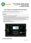
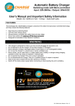
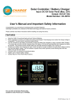
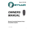
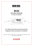
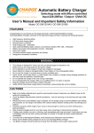
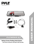
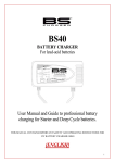
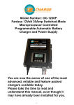
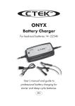
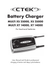
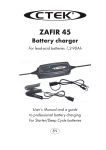
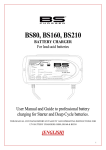
Automatic Battery Charger & Maintainer
Input: 100-240Vac / Output: 6/12 Volt DC (1 Amp)
User’s Manual and Important Safety Information
Model: OC-61201
- - - - - - - - - - - - - - - - - - - WARNINGS - - - - - - - - - - - - - - - - - - - - •
•
•
•
•
•
•
•
•
Read instructions prior to use. These instructions form part of the warranty conditions.
This appliance must not be used or played with by infirm persons or children.
If using Generator power, please use a Surge Protector to protect the unit from Voltage
Spikes.
Do not attempt to use the charger if it has been dropped or damaged.
Never attempt to charge a damaged battery, frozen battery or non-rechargeable battery.
Do not use the charger in a closed area or poorly-ventilated area.
Never smoke, use an open flame, or create sparks near a battery or charger during charging
operation as this may cause an explosion / explosive gas.
Do not operate the charger if the cord or plug is damaged.
Do not disassemble the charger. Take it to a qualified person if a repair is required. (No
serviceable Parts inside)
FEATURES
Congratulations on purchasing an AS/NZS Approved OzCharge Automatic Switching Mode
Battery Charger and Maintainer.
•
•
•
•
High frequency, High Efficiency Switching Mode Charger and Maintainer
Suits all Lead Acid Type Batteries. (Conventional, AGM & Gel)
Selectable 6 Volt & 12 Volt Output
Includes both crocodile clips and ring terminal leads
1
OC-61201 User’s Manual - Rev 1.0
CONTROL AND INDICATORS
1 Charging Status Display LED (3 x LED’s)
Power - Red
Charging - Orange
Fully Charged / Float - Green
Fault - Red
2 Voltage Output Select Switch
Select 6 Volt or 12 Volt Output
RECOMMENDED BATTERY CAPACITY
The maximum recommended battery Capacity for OC-61201 (1 Amp) Battery charger is 20AH.
We always recommend that you check the Battery Manufacturers specifications before using
this charger.
2
OC-61201 User’s Manual - Rev 1.0
OPERATING INSTRUCTIONS
The OzCharge Battery Charger is easy to operate and requires no technical experience.
It comes with a quick connect fly lead and 2 different kinds of connectors, crocodile clips and a
ring terminals. The ring terminals are perfect for permanent connection to your battery. You can
connect the lead to the battery and tuck the lead away while you are using your vehicle and
when you get back to your garage simply plug the lead back into the charger.
The intelligent integrated charging circuit in this charger is designed for permanent connection
to your battery, it senses when your battery is charged and it will maintain your battery in prime
condition for when you need to use it.
Its small current and intelligent charging circuit will help you to maintain your battery in excellent
condition so you get the maximum life out of it.
1. Pre-Charge Check
(a) Check the Battery Electrolyte level (Non-sealed Batteries). - If necessary, remove the vent
caps and add distilled water so the levels are halfway between the upper and lower fill
lines.
(b) Check the Voltage Output Switch on the charger and make sure it’s on the correct voltage.
(c) Location – Ensure the Battery is in a well ventilated area. Keep the Charger as far away
from Battery as the cables permit. Never place the charger directly above the battery
being charged as gasses from the Battery will corrode and damage the charger. Also,
keep the charger away from high corrosion / wet and moist areas.
2. Connecting the Battery charger to you Battery
(a) If the Battery is out of the vehicle
(i)
Connect the Red lead from the charger to the positive (+) battery terminal.
(ii)
Connect the Black lead from the charger to the negative (-) battery terminal.
(b) If the Battery is still in the vehicle
Determine if the vehicle is positively (+) or negatively (-) earthed.
(i)
If Negatively Earthed (Most Common) – FIRSTLY Connect the Red (+) battery
charger lead to the positive (+) Battery post and then connect the Black (-) battery
charger lead to the vehicle’s chassis and away from the fuel line.
(ii)
If Positively Earthed – FIRSTLY Connect the Black (-) battery charger lead to the
negative (-) battery post and then connect the Red (+) battery charger lead to the
vehicle’s chassis and away from the fuel line.
3. Connect the battery charger to the Mains power (240Vac)
(a) The Charger will automatically start when AC power is connected and switched on.
(Note: If the Fault Indicator LED illuminates Red, please check your connections as it’s
likely that the Positive and Negative Leads are reversed. Refer to Trouble Shooting Page
for further information)
3
OC-61201 User’s Manual - Rev 1.0
The Charging process
The charging stages are as follows:
●Bulk Charge:
Charges using a constant maximum current (1A) until the battery
reaches 7.2V (6 Volt Batteries) or 14.4V (12 Volt Batteries)
(LED Colour - ORANGE)
●Fully / Float:
Battery is fully charged and is being maintained.
(LED Colour - GREEN)
4. Disconnecting the Battery charger from Battery.
(a) If the Battery is out of the vehicle.
(i) Switch OFF and Remove the AC Power Socket from the outlet.
(ii) Remove the Black lead and then the Red lead.
(iii) Check electrolyte levels if possible.
(As they may need topping up with distilled water after charging)
(b) If the Battery is in the vehicle.
(i) Switch OFF and Remove the AC Power Socket from the outlet.
(ii) Remove the lead from the vehicle chassis.
(III) Remove the lead from the battery.
(iv) Check electrolyte levels if possible.
(As they may need topping up with distilled water after charging)
LED STATUS INIDICATOR TABLE
Power
Red
ON
ON
ON
ON
ON
OFF
A.C. Power connected, battery disconnected
Bulk Charging
Level 1 Charging
Level 2,3 Charging
Battery Reverse polarity connection
A.C. Power OFF
4
Charging
Amber
OFF
ON
ON
OFF
OFF
OFF
Full
Green
OFF
OFF
OFF
ON
OFF
OFF
Fault
Red
OFF
OFF
OFF
OFF
ON
OFF
OC-61201 User’s Manual - Rev 1.0
CHARGING CURVE (VOLTAGE)
TROUBLE SHOOTING
Problems
Charger does
not work
Indication
No Indicator
lights on
Charger has
no DC output
Fault LED
is On.
- Output is short circuited
- Reverse polarity connection to
Battery
No Charging
Current
Fault LED
is ON
- Battery is severely sulphated
- Battery has a damaged cell
- Overheat protection mode
Long
charging
time, Full
light does not
come on
Fault LED
is ON
Possible causes
- No AC power
- Battery capacity too large
- Battery is defective
5
Suggested solution
- Check AC connections and make
sure Power Point is switched ON
- Check DC connection between
charger and battery and make sure
they are not short circuiting.
- Check that the crocodile clips
haven’t fallen off the battery.
- Check that the crocodile clips / ring
terminals are connected to the
correct polarity.
- Check the Battery condition, age
etc.
- Battery may need replacement.
- Move battery & Charger to cooler
environment
- Check the charger specification
matches the battery capacity.
- Battery cannot be charged and
must be replaced.
OC-61201 User’s Manual - Rev 1.0
SPECIFICATIONS
Normal
Withstand
Unit
100-240
90~264
Vac
50/60
47-63
Hz
Unload input power : at 230Vac input
1.5
max.
W
1-4
Input current consumption at 230Vac input, output 13.5V 1000mA loading
.019
±10%
Aac
1-5
Nominal efficiency: at 115Vac, output 13.5V 1000mA loading
>78%
Nominal efficiency: at 230Vac, output 13.5V 1000mA loading
>82%
4.4
±0.3
Vdc
1000
±10%
mAdc
1
AC Power Input Characteristics
1-1
Input voltage :
1-2
Input frequency :
1-3
2
Charging Output Control Characteristics
2-1
Battery Condition Check → Bulk Charge → Float Charge (Full)
2-2
Charging output control for 6V mode
2-2-1
Bulk charging activity conditions: Battery Voltage is above
2-2-2
Bulk charging current control
2-2-3
Level 1 upper limited
7.2
±0.2
Vdc
2-3-4
Level 2 lower limited
6.75
±0.2
Vdc
2-3-5
Level 3 upper limited
7.0
±0.2
Vdc
2-3
Charging output control for 12V mode
2-3-1
Bulk charging activity conditions: Battery Voltage is above
8.8
±0.3
Vdc
2-3-2
Bulk charging current control
1000
±10%
mAdc
2-3-3
Level 1 upper limited
14.4
±0.2
Vdc
2-3-4
Level 2 lower limited
13.5
±0.2
Vdc
2-3-5
Level 3 upper limited
14.0
±0.2
Vdc
2-4
Unload output voltage when disconnected from battery
0.5
Max.
Vdc
2-5
Battery flow back current (to the charger) when connected to 12V battery, AC
1
Max.
mAdc
power disconnected
3
Safety & Protection
3-1
Built in Temperature Protection.
3-2
Output Short Circuit Protection, Reverse Polarity Protection
4
Electrical Parts
4-1
Input Connector
Wall mount / 3 Pin
4-2
Out Put Connector
4 feet - Quick connect
4-3
Extension leads
2 feet – Crocodile clips / ring terminals
5
Physical Parameters
5-1
Plastic Enclosure Dimensions
100(L) x 65(W) x 36(H) mm
5-2
Net weight :
approx. 400g
6
Environmental Characteristics
6-1
Operating temperature :
0 to 45 oC
6-2
Storage temperature :
-25 to 85 oC
6-3
Operating Humidity range :
0 to 90% RH
6-4
Cooling:
Passive / Natural
* Specifications subject to change without notice
6
OC-61201 User’s Manual - Rev 1.0
2 YEAR MANUFACTURER WARRANTY
Zylux Distribution Pty. Ltd. (OzCharge) warrants to the Customer that this product is substantially
free from defects in materials and workmanship under normal use for a period of 2 Years from the
Date of Purchase.
Please ensure you keep a copy of your receipt on file as this will be required for proof of purchase
and to validate your warranty.
Obtaining Warranty Service
Within the warranty period, the Customer must contact the authorised supplier / retailer where the
product was purchased or alternatively you can contact the OzCharge service centre through one
of the following methods:
Hotline: (03) 9482 2203
Website: www.ozcharge.com.au
If the Authorised Supplier and / or OzCharge service centre concludes that while under normal
use, a product failure or malfunction occurred during the warranty period and was caused by a
defect in material or workmanship (see Exclusions), the Customer will be asked to ship to the
nearest service point. The product must be packaged appropriately for safe shipment. To prove
that the product is under warranty, the customer should enclose a copy of their receipt for proof of
purchase. It is recommended that returned products be sent by registered mail as Zylux
Distribution Pty. Ltd. (OzCharge) accepts no responsibility / liability for goods lost or damaged in
transit. Return Shipping costs to be incurred by the Customer.
Exclusions
If upon receiving a product for repair and if testing and examining the product has disclosed that
the alleged defect or malfunction in the product does not exist or was caused by the Customer or
any third persons misuse, physical abuse, water damage, unauthorised attempts to open, repair
or modify the product or improper installation, this will not be covered under this warranty.
This Warranty is void if:
1. The product has been tampered or repaired by unauthorised personnel.
2. If connected to generator power without using surge protector
3. The warranty seal is broken or altered.
4. The warranty period has expired.
7
OC-61201 User’s Manual - Rev 1.0
Distributed by Zylux Distribution Pty. Ltd.
Website: www.ozcharge.com.au
8
OC-61201 User’s Manual - Rev 1.0