1
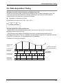
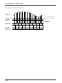
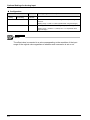
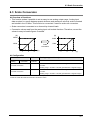
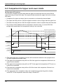
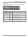
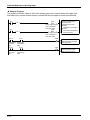
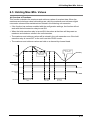
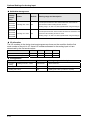
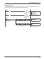
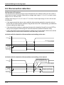
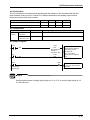
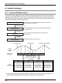
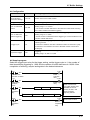
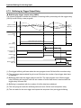
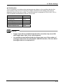
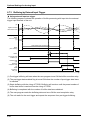
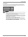
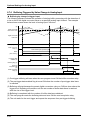
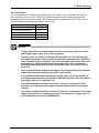
6.7 Buffer Settings I/O Allocation The I/O numbers in the timing chart and program are shown on the condition that the first word number of the unit is 10. Actual I/O numbers allocated to the analog input unit are determined by the first word number. The buffer function is allocated to I/O on CH0. CH1 to CH3 all operate simultaneously with the I/O on CH0. CH0 to CH3 *1 Buffer execution relay Y108 *2 Pre-trigger data enabled X11B *3 Buffering flag X119 *4 Buffering completion flag X11A *5 Read completion relay Y10A NOTES • Trigger input will be prohibited with the buffer execution relay turned ON after trigger input. Input, if any, will be ignored. • It is possible to start buffering with the trigger input even if the number of pre-trigger data items has not reached a specified number. (The area where pre-trigger data is not acquired is 0). • TRIG0 to TRIG3 for external input trigger selection show input terminals. Keep in mind that none of them supports CH0 to CH3. • The buffer function will not be executed if “Not use” is selected with the external input trigger even if “External input trigger” is selected as “Trigger type” in the configuration menu of the FPWIN GR7. 6-21