1
-PS
USER'S MANUAL
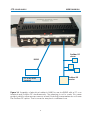
POWER SUPPLY
Disconnect
power before
opening!
12
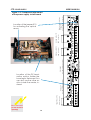
BNC connector
Trigger input (TTL)
D9 sub female connector
Profibus DP
D9 sub female connector
Location of the DP termination resistor. Solder the
loose leg to the board. You
can also use the other resistor inside the meter, instead.
Visilab Signal Technologies
BNC connector
BNC connector
RS232/485
Analog output V1
Analog output V2
Location of the jumper X10
for activating the optical
sensor
D9 sub female connector
Optical sensor interface
for triggering
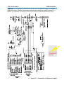
Figure L1-2 Component placement
of the power supply circuit board