1
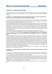
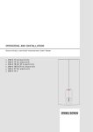
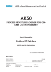
LAN232
BRIDGING UNIT FOR PROCESS SENSORS
USER'S MANUAL
Model LAN232
Unit information:
Model & Rev:
Serial number:
-
Rev:
PCB's:
Made in Finland
Manual printed in Mäntsälä, Finland
PART #700503
Visilab Signal Technologies
Address:
Keskustie 15
FI-07560 PUKKILA
FINLAND
Oy
Tel.:
+358-45-635 4885
Y 0631208-0 ALV Rek.
VAT FI06312080
2015-06
1
Copyright (c) 2015 Visilab
Signal Technologies Oy
e-mail:
[email protected]
Mäntsälä Reg. 365.258
www.visilab.fi
LAN232
USER'S MANUAL
CONDITIONS OF GUARANTEE, COPYRIGHT NOTICE AND LIABILITIES OF THE MANUFACTURER
The manufacturer (Visilab Signal Technologies Oy) grants a guarantee of two years for the buyer of
the power LAN232 meter from the date of purchase. The guarantee covers all faults and misalignments
which are in the equipment at the moment of purchase including those which appear during the
guarantee period. The manufacturer is liable of repairing the instrument without cost to the buyer. The
manufacturer can ship a new instrument of equivalent value and status if considered as a better
solution than repairing. The buyer is liable of paying the freight costs to the factory of the faulty unit.
The unit must not be sent to the manufacturer without a permission from the manufacturer. Units sent
without a permission will be repaired at the cost of the buyer.
The guarantee does not cover wearing parts, like batteries, LAN232 or motors. The guarantee does
not cover faults caused by errors or neglects of the user nor those faults which are caused by
deliberate damaging. The guarantee does not cover faults caused by incorrectly installed cables
or conductors. The guarantee does not cover any damages to the user or to any third party
independently of the way how the instrument has been used. The guarantee does not cover faults
caused by natural phenomena like lightnings or floods, nor user errors like dropping or hitting the unit.
The guarantee is void if the unit is sold to any third party. All faults which are not covered will be
repaired at the cost of the buyer.
If opening of the instrument has been attempted at those parts which are not intended for the user,
the manufacturer can refuse to repair or service the instrument. Then the instrument will be shipped
back to the buyer at the cost of the buyer. Such parts are the light source, the optical head and parts
on the electronics boards. The instrument can be opened only strictly according to the instructions
in this manual and should not be disassembled unnecessarily. Also, if some parts can not be opened
with a reasonable force, they should be left to avoid any damage.
Copyright (c) 1994 - 2015 Visilab Signal Technologies Oy, All Rights Reserved
Visilab Oy reserves all rights to changes and modifications in the looks, specifications, optical and
electronic design, electronic and software interfaces and computer programs, and also the right to
change the retail prices of the instrument or its parts without any notice to present or potential
customers. All copyrights and design rights belong to Visilab Oy. The PC programs, which have been
sold to the buyer, can be used and copied freely for his own use but can not be sold to any third party.
The manufacturer is not responsible for any casualties, damages or accidents which the user has
caused directly or indirectly with this instrument, either to himself or to any third party, independent
on the instrument being used correctly or not.
Important warnings are highlighted in this manual with red color.
Recommendations are in blue and important instructions are in brown.
2
LAN232
USER'S MANUAL
EC Declaration of Conformity
We
Visilab Signal Technologies
Lahdentie 58
FI-04600 MÄNTSÄLÄ
FINLAND
declare that the
LAN232 bridging unit for process sensors
meet the intent of the EMC directive 89/336/EEC. Compliance is based on the following harmonized
standards:
Emissions:
EN 50 081 part 2 (industrial environment):1993 referring to :
EN 55 011 radiated, Class A, Group 1
EN 55 011 conducted, Class A, Group 1
Immunity:
EN 50 082 part 2 (industrial environment):1992 referring to (both radiated and
conducted fields):
EN 61000-4
IEC 1000-4
ENV 50140
ENV 50141
ENV 50204
I certify that the apparatus identified above conforms to the requirements of Council Directive 89/
336/EEC.
--------------------------------------------------------Henrik Stenlund
managing director
5th April 2006
Note for users:
When the apparatus identified above is connected by someone to become a part of an industrial
control system, he is also responsible for the EMC compatibility of the resulting system. He is also liable
of providing the necessary optical or galvanic isolations for signals and transient absorbers for other
lines to conform to the EMC directives. The expansion modules to be attached to the meter
electrically and mechanically are designed and implemented in the same fashion and are claimed
to be compatible with the EMC directive without individual testing.
The apparatus have been individually tested according to DIN VDE0701 and DIN VDE0702 for
electrical safety.
3
LAN232
USER'S MANUAL
EC Declaration of Conformity
We
Visilab Signal Technologies
Lahdentie 58
FI-04600 MÄNTSÄLÄ
FINLAND
declare that the products which are put on the EU market:
LAN232 bridging unit for process sensors
meet the intent of the RoHS directive 2002/95/EC and the WEEE directive 2002/96/EC. Compliance is
based on the following.
The instruments belong to Category 9 "Monitoring and Control Instruments" of the WEEE directive and
thus are not required to fulfill the said directives.
I certify that the apparatus identified above conforms to the requirements of Council Directives 2002/
95/EC and 2002/96/EC.
--------------------------------------------------------Henrik Stenlund
managing director
3rd April 2006
Note:
In spite of the fact that the products are not required to fulfill the directives, we make every effort to
comply with the directives in practice. When the Category 9 is moved to be covered the same
requirements as other categories do, we are ready to certify that these products comply with the
directives.
Specifications of the unit, model LAN232:
Operating -10 to +60 C 20 - 90 %RH noncondensing ambient, max 10 W continuously.
Safety and EMC compliance with UL60950, TÜV EN60950-1, EN55022 (CISPR22) CLASS B,
EN61000-3-2,-3, EN61000-4-2,3,4,5,6,8,11, ENV50204, EN55024, LIGHT INDUSTRY LEVEL, CRITERIA A. Tested for electrical safety according to DIN VDE0701 and VDE0702.
4
LAN232
USER'S MANUAL
Contents
1. Introduction and Taking into Use...6
Connecting the Cables and Starting the Meter...6
2. Basic Features of the LAN232...10
RS232 Operation...10
Speed Setting...10
RS485 Operation...10
Appendix 1. Schematic of Electrical Connections for LAN232. If you open the
cover, please, disconnect the power lead first to avoid a shock!...12
Appendix 2. The circuit board with locations of all important components....13
Appendix 3. The circuit board with locations of all important jumpers, their default and optional positions, RX = receiver line, TX = transmitter line to/from UART.
Note that port A is reserved for RS485 communications when activated with
J601. Other ports can be left as RS232 if required....14
Index...15
5
LAN232
USER'S MANUAL
1. Introduction and Taking into Use
The LAN232 is designed for use with your process sensors made by Visilab, any model. It provides your
meter with RS232-based communications for up to eight sensors and 40 m legs maximum. Optionally
it offers RS485 communications for a great number of slaves and up to 1200 m network length
measured from end-to end. The operating speeds are 9600 bauds (NORMAL) or 38400 bauds (HIGH
SPEED). In the following find the proper use of each connector in the box. For any details of use of
the sensor itself, refer to the corresponding User's Guide.
LAN232 is taken out of its package carefully and it should be inspected for any damage during
shipping. If any damage is visible, contact the manufacturer or the representative from which the
unit was bought. The following items should be available:
1. LAN232 unit
2. User's guide (this)
3. Splitting RS232 cables of 0.5 m in length, 4 pieces
4. Wall supply cable with an IEC320 socket at one end
5. DIN rail mounting kit
6. Other optional items ordered
If something is missing, inform your dealer and he will ship any missing parts. The instrument is ready
for use after connecting the cables and power plug.
LAN232 is a self-powered bridging unit connecting any sensor made by Visilab to your PC. You can
connect up to eight slaves to it to acquire data from a complex sensor arrangement in your
production plant. The default communications is RS232 at 9600 bauds. If you plan to change this, do
the corresponding settings in each sensor according to the User's Guides first using your regular RS232
system. Then, configure the LAN232 accordingly as described in the following chapters.
The casing has a number of venting holes for air circulation. The unit is intended for installation into
either electrical cabinets or as an office accessory. It has rubber feet for comfortable desktop
operation too. It is not watertight in any degree and should not be installed into such conditions
where there is a risk of letting water inside. The LAN232 accepts any AC voltage between 85 and 240
Volts of 50/60 Hz. Also DC voltage is acceptable. Check the unit's label for certifications and valid
approvals. For wall power inlet, there is an IEC320 connector at one end of the LAN232. A suitable
cable with the proper wall plug at the other end is supplied. Minor variations may exist in this respect
as conditions vary from country to country and the plugs are often very different. This is described
in the following.
Connecting the Cables and Starting the Meter
To preserve the cables and connector for the operating life of the instrument handle them carefully
and avoid too much force while fastening and loosening. Refer to Figures 1 to 3 for connector
locations and typical cable connections in applications. In practice, there are more legal combinations than the ones shown. Use the standard RS232 cable of your instrument for connecting to
LAN232. if you don't have it available, you can use any regular one-to one serial cable with D9 male
and female connectors at the ends. The pins 2, 3 and 5 are only used in this direct cable. These are
low-cost consumable in PC stores and are varying in length. If possible, choose the one having some
sort of shielding in the cable to minimize the risk of EM interference and having a sufficient length.
6
LAN232
USER'S MANUAL
operation. A twisted-pair cable with shielding is usually sufficient. There are termination resistors
available, one inside the meter and another inside the LAN232. Refer to the meter's own User's Guide
for details and to Appendix 2 for finding the other resistor and its jumper.
PORTS B & F
D9 MALE (X3)
PORTS D & H
D9 MALE (X5)
PORTS C & G
D9 MALE (X4)
PORTS A & E
D9 MALE (X2)
MASTER (PC)
D9 FEMALE
(X1)
Speed switch
Figure 1. Location of all connectors on the front panel. note that the MASTER port
is always reserved for the master alone. No slaves should be connected to it in
RS232 mode. In RS485 mode the same connector has some pins available for building the network (refer to appendices).
7
LAN232
MASTER (PC)
D9 FEMALE
(X1)
USER'S MANUAL
PORTS A & E
D9 MALE (X2)
PORTS B & F
D9 MALE (X3)
PORTS D & H
D9 MALE (X5)
PORTS C & G
D9 MALE (X4)
Figure 2. Electrical connectors for model LAN232 with their types indicated.
8
LAN232
USER'S MANUAL
AK50
AK50
AK50
AK50
AK50
AK50
AK50
AK50
Figure 3. Typical connections in a multi-slave system
9
LAN232
USER'S MANUAL
2. Basic Features of the LAN232
RS232 Operation
LAN232 can operate as a bridging unit between PC master and a number of instruments working
as slaves. The lowest level hardware communications can be RS232 with up to 40 m legs of cables
at 9600 bauds (NORMAL SPEED). The maximum recommended leg for the HIGH SPEED setting 38400
bauds is 15 m legs for reliable operation.
The number of slaves is maximum eight, each slave connected to the four D9 standard RS232 ports
of the LAN232 unit. Four slaves can be connected directly to the unit and you can use the splitting
cables when the number of slaves increases. Detach one slave from LAN232 and install the splitting
cable instead. Connect now two slaves to these open ends. The splitting cables are transparent and
have no effect on the system. You can use freely any of the available ports reserved for slaves. The
one marked for master (PC) is reserved for that purpose and should not be used for the slaves.
The default setting of LAN232 is 9600 bauds and operation in RS232.
Important
Note that each meter's slave address must be made unique before connecting it to the network,
either RS232 or RS485 based. Refer to the user's guides of each sensor and perform this as a first task.
Speed Setting
The speed setting of LAN232 is can be changed with the switch as shown in Figure1. When changing
the speed, note the following:
o first, change the speed of the meters, one by one in Keyboard mode and return to packet
protocol, select the next slave and repeat. That slave becomes invisible temporarily due to
speed difference
o second, change the speed of LAN232
o third, change the speed of the PC software and now you can talk to the slaves again
If you do this in an incorrect order, you may invite trouble as you cannot communicate at some point
with the slaves. Repeat this set of steps also when changing back the speed.
RS485 Operation
The bridge can be operated as RS485 on the lowest level of hardware with twisted pair cables for
longer distances and by using the regular RS232 cables for shorter distances (< 20m). At 9600 baud
(NORMAL SPEED) the legs can be up to 1200 m and at 38400 bauds (HIGH SPEED) it can be up to 100
m. You can also have several tens of slaves in the network, possibly up to 100. The current versions
of the PC software support data acquisition from up to eight slaves at a time of these. Mill-wide
networks in small scale and low cost are thus possible. The cable between the nodes will probably
cost more than the LAN232 unit.
To change from the default RS232 to RS485 operation, you need to change first the mode of each
meter to operate as RS485, refer to their own User's Guides. Then you need to open the LAN232 unit
cover and find a set of jumper plugs. After changing them as indicated in Appendix 3., you can
change the corresponding selection in each and every slave to be connected to this two-wire
10
LAN232
USER'S MANUAL
network. When finished, you are ready to operate this simple network as no changes are required
for the software. Disconnect the power plug before opening the cover! There are dangerous high
voltage parts inside the box in the AC-DC converter module.
You have also the special opportunity of selecting part of the ports for RS232 and the rest of them
for RS485. This may be useful if you have slaves which absolutely cannot be working as RS485 or there
is some reason you don't want to do it. Port A is reserved always for running the RS485 network when
it is activated by selection of jumper J601. The other ports can be used freely as RS232 or RS485 when
RS485 has been activated. Else, only RS232 communications is allowed in all ports. There is a line
termination resistor which can be taken into use by JMP601. Use it only if required to avoid
unnecessary line loading. Use twisted pair wiring for RS485.
The RS485 network is physically connected with the same wires and cables as before, the TX/RX lines
being now used by A/B lines of the RS485. These same lines are available in the MASTER connector
X1 too (pins 5 - 8). There is also a screw connector inside the box on the circuit board (X6) for building
a network with a separate high-quality cable. There is also a rubber plug stopped opening in the box
wall just for this purpose. Your mill engineer is capable of getting a cable protector installed to this
hole. It would be recommended to use this connector, especially for long distance operation.
When building a network based on RS485, you might encounter a phenomenon where the network
runs fine as RS232 but refuses to work completely as RS485. The most common reason for this is that
either the master's RS485 wire pair ordering is incorrect or the same problem lies at slaves. Switch the
two wires from the screw terminal with eachother and the network should start operating. Make the
network operate correctly with one slave at a time and increase the number of slaves until all work.
This is recommended to be done before you even install the long cable to the mill, everything being
coiled at that time for simplicity.
Indicators
There are two indicator lights on the front panel. The one marked as POWER indicates a working
power supply of this unit. The second one (SPEED) indicates the selected communication speed. If
it is lit, you are using the HIGH SPEED (38400 bauds), else you are using the NORMAL speed (9600
bauds). Just toggle the switch near the LED to change the setting and it is accepted in a second.
11
LAN232
USER'S MANUAL
Appendix 1. Schematic of Electrical Connections for LAN232. If you open the
cover, please, disconnect the power lead first to avoid a shock!
Disconnect
power before
opening!
Figure L1. Schematic of the LAN232 connectors and jumper plugs
12
LAN232
USER'S MANUAL
Appendix 2. The circuit board with locations of all important components.
ports C & G
master port
power input
+10...+24VDC
ports A & E
ports B & F
RS485 termination
jumper
Figure L2 Circuit board for LAN232R3
13
ports D & H
RS485 screw
connector
LAN232
USER'S MANUAL
Appendix 3. The circuit board with locations of all important jumpers, their default
and optional positions, RX = receiver line, TX = transmitter line to/from UART. Note
that port A is reserved for RS485 communications when activated with J601. Other
ports can be left as RS232 if required.
RS232
RS485
RS232
RS232
RS485
RS232
jumpers
J1001 port A RX - J1002 port E RX
J1003 port A TX - J1004 port E TX
J1005 port B RX - J1006 port F RX
J1007 port B TX - J1008 port F TX
RS485 RS232
RS485
RS485 RS232
RS485
jumpers
J1013 port D RX - J1014 port H RX
J1015 port D TX - J1016 port H TX
jumpers
J1009 port C RX - J1010 port G RX
J1011 port C TX - J1012 port G TX
RS485
RS232 !
jumper
J601
Figure L4-1 Circuit board for LAN232R3 with jumper locations. Do not change
other jumpers except the RS485 termination if required.
14
LAN232
USER'S MANUAL
Index
A
Appendix 1. Schematic of Electrical Connections 12
Appendix 2. Use of the optional optical sensor int 13, 14
Assembly of electrical cables 7
B
Basic Features of the Instrument 10
C
Cables 6
Conditions of Guarantee 2
Connecting the Cables and Starting the Meter 6
E
EC Declaration of Conformity 3, 4
I
Important 10
Indicators 11
Introduction and Taking into Use 6
S
Schematic 12
15