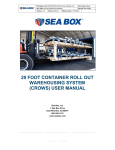
Download (crows) user manual
Transcript
File Name: MAN-OPS-CROWS40_40Foot_User_Manual_v2 Doc Type: Manual Doc Title: 40 foot CROWS User Manual Doc ID: SBI-1000247 Version: 1-0 Status: Effective Effective Date: 15/07/2014 40 FOOT CONTAINER ROLL OUT WAREHOUSING SYSTEM (CROWS) USER MANUAL Sea Box, Inc. 1 Sea Box Drive East Riverton, NJ 08077 856-303-1101 www.seabox.com COMMERCIAL IN CONFIDENCE File Name: MAN-OPS-CROWS40_40Foot_User_Manual_v2 Doc Type: Manual Doc Title: 40 foot CROWS User Manual Doc ID: SBI-1000247 Version: 1-0 Status: Effective Effective Date: 15/07/2014 Page: ii SAFETY WARNINGS Operators involved in moving, stacking, loading or unloading CROWS should be suitably qualified and experienced, and wear appropriate approved Personnel Protective Equipment (PPE) It is recommended that the following items should be worn: Appropriate long sleeved shirts, and long pants Steel capped boots Suitable gloves Safety glasses Hard hat Failure to follow the warning may result in serious injury to personnel. Suitable Material Handling Equipment (MHE) must be used to move, load, unload and stack CROWS. Key safety requirements include: The MHE has to be rated and capable of lifting the Maximum Gross Weight (MGW) of CROWS, including secured load. The MHE needs to have appropriate lifting tines to suit the CROWS tine pockets. All moving, loading and unloading activities need to be carried out on suitable level, even and compacted surfaces. Particular attention is needed when moving, loading and unloading stacked CROWS assemblies to ensure MHE is capable of handling total gross weight of stack. Failure to comply may result in severe injury or death to personnel and damage to equipment. COMMERCIAL IN CONFIDENCE File Name: MAN-OPS-CROWS40_40Foot_User_Manual_v2 Doc Type: Manual Doc Title: 40 foot CROWS User Manual Doc ID: SBI-1000247 Version: 1-0 Status: Effective Effective Date: 15/07/2014 Page: iii When loading and unloading CROWS ensure all personnel stand clear of the CROWS and the Container, in particular operators/spotters must ensure that they: Do not stand between the CROWS and the shipping container during loading. Do not extend any part of the body under a suspended CROWS platform. Failure to comply may result in severe injury or death to personnel and damage to equipment. The CROWS must only be loaded up to the maximum permissible payload, depending on stacking arrangement as specified in this manual. Loads must be evenly distributed across the CROWS deck surface. Loads must be secured using suitable rated and certified load restraint equipment, and only secured to the CROWS using the certified tie-down points as marked on the CROWS platform. Tie down rails are provided along both sides of the CROWS and are capable of restraining up to 3.8 tonnes, per load restraint bay. Ensure only one restraint is applied to each tie rail bay. Failure to comply may result in severe injury to personnel or damage to equipment. Before moving or loading CROWS as a nested configuration, the operator is to confirm that all interfacing twist locks are positively engaged. Always lift a stacked or nested CROWS via the base CROWS, either by overhead MHE or forklift. Double stacking 40 foot CROWS on a truck or trailer using CROWS Claws is not permitted. Failure to comply may result in severe injury or death to personnel and damage to equipment. COMMERCIAL IN CONFIDENCE File Name: MAN-OPS-CROWS40_40Foot_User_Manual_v2 Doc Type: Manual Doc Title: 40 foot CROWS User Manual Doc ID: SBI-1000247 Version: 1-0 Status: Effective Effective Date: 15/07/2014 Page: iv Stacked CROWS for transportation or warehousing shall have heavier loads on the lower levels. Failure to comply may result in severe injury or death to personnel and damage to equipment. The CROWS end forklift pockets are not to be used for lifting the CROWS. The tine pockets provided at the end of the CROWS is for Roll in/Roll out loading and unloading into a 40ft shipping containers. Failure to comply may result in severe injury or death to personnel and damage to equipment. If at any time the CROWS legs cannot be fully tightened i.e. the leg is loose after fully tightening the bolt, the legs have been damaged and must be repaired or replaced. Four high stacking with 4 foot legs is not allowed, maximum warehousing for 4 foot legs is 3 high. The use of 4 foot legs is not permitted in all configurations, please see Chapter 1: 40 foot and 20 foot Configurations for more detail. Failure to comply may result in severe injury or death to personnel and damage to equipment. COMMERCIAL IN CONFIDENCE File Name: MAN-OPS-CROWS40_40Foot_User_Manual_v2 Doc Type: Manual Doc Title: 40 foot CROWS User Manual Doc ID: SBI-1000247 Version: 1-0 Status: Effective Effective Date: 15/07/2014 Page: v FOREWORD Authority Sea Box Inc. (SBI) is the Design Authority for the Container Roll Out Warehousing System (CROWS). For safety purposes, this manual is a controlled item and as such is not to be modified or altered in any way. Any suggested improvements relating to design, functionality or operating procedures are actively encouraged. Any such suggestions or notifications are to be sent to: [email protected] or (02) 6162 2826 Manual Currency and Version Control Updated versions of this manual will be available on requests sent to [email protected]. SBI will make best endeavours to ensure that SBI – CROWS customers are updated with subsequent versions of this document. Manual Layout and Applicability This manual is divided into two sections: Chapter 1: Description and Tabulated Data. This section provides familiarity with the equipment and provides specification data intended to assist users conduct operational planning. Chapter 2: Operating Instructions. This section provides instruction on: 1. Preparation for use 2. Assembly 3. Loading 4. Unloading 5. Warehousing 6. Servicing COMMERCIAL IN CONFIDENCE File Name: MAN-OPS-CROWS40_40Foot_User_Manual_v2 Doc Type: Manual Doc Title: 40 foot CROWS User Manual Doc ID: SBI-1000247 Version: 1-0 Status: Effective Effective Date: 15/07/2014 Page: vi TABLE OF CONTENTS Contents Safety Warnings ............................................................................................................ii Foreword ...................................................................................................................... v Authority.................................................................................................................... v Manual Currency and Version Control....................................................................... v Manual Layout and Applicability ................................................................................ v TABLE OF CONTENTS ................................................................................................vi LIST OF TABLES ....................................................................................................... viii LIST OF FIGURES ..................................................................................................... viii LIST OF ANNEXES ......................................................................................................ix Chapter 1 Description and Tabulated Data ................................................................... 1 Introduction ............................................................................................................... 1 40 Foot CROWS Description and Layout .................................................................. 1 Deployment Configurations ....................................................................................... 2 Characteristics and Tabulated Data .......................................................................... 8 40 Foot and 20 Foot Configurations .......................................................................... 9 Two 20 Foot CROWS End Stacked ....................................................................... 9 Double Stacked 20 foot CROWS Centre Mounted .............................................. 10 Single Stacked 20 foot CROWS Centre Mounted ............................................... 12 Two Nested 20 foot CROWS .............................................................................. 13 Warehoused 40 foot CROWS ............................................................................. 15 Chapter 2 Operating Instructions ................................................................................ 17 Introduction ............................................................................................................. 17 Preparation for use.................................................................................................. 17 Walk Around Inspection ....................................................................................... 17 Tie Down Rail Check ........................................................................................... 17 CROWS Mounting and Lifting Points Check ........................................................ 18 CROWS Rollers Check ........................................................................................ 19 CROWS Deck and Underside Plating Check ....................................................... 20 CROWS Legs Check (If posts are used).............................................................. 20 CROWS Transport Locking Bars Check .............................................................. 21 Assembly ................................................................................................................ 22 COMMERCIAL IN CONFIDENCE File Name: MAN-OPS-CROWS40_40Foot_User_Manual_v2 Doc Type: Manual Doc Title: 40 foot CROWS User Manual Doc ID: SBI-1000247 Version: 1-0 Status: Effective Effective Date: 15/07/2014 Page: vii CROWS Nesting Installation ................................................................................ 22 CROWS Legs Installation .................................................................................... 24 CROWS Ramp Installation .................................................................................. 28 CROWS Stacking Installation .............................................................................. 29 CROWS Claws Installation .................................................................................. 30 Loading ................................................................................................................... 36 Single CROWS Loading Procedure ..................................................................... 36 Stacked CROWS loading procedure .................................................................... 39 Unloading ................................................................................................................ 39 Single and Stacked CROWS unloading procedure .............................................. 39 Stacked 20 foot CROWS of 40 foot Truck and Trailer Transportation .................. 40 CROWS Warehousing Installation Procedure ......................................................... 44 Ground requirements ........................................................................................... 44 Nested Warehousing Installation ......................................................................... 44 Stacked Warehousing Configuration.................................................................... 44 Lifting and Moving ................................................................................................... 48 Single loaded CROWS lifting ............................................................................... 48 Double Stacked Lifting ......................................................................................... 50 Lifting Nested Crows............................................................................................ 51 Operator Maintenance ................................................................................................ 53 Introduction ............................................................................................................. 53 Responsibility .......................................................................................................... 53 Maintenance Procedure .......................................................................................... 53 Inspection ............................................................................................................ 54 Maintenance and Repairs .................................................................................... 56 Legs Maintenance ............................................................................................... 58 Verification........................................................................................................... 59 REVISION HISTORY.................................................................................................. 62 ANNEXES .................................................................................................................. 62 COMMERCIAL IN CONFIDENCE File Name: MAN-OPS-CROWS40_40Foot_User_Manual_v2 Doc Type: Manual Doc Title: 40 foot CROWS User Manual Doc ID: SBI-1000247 Version: 1-0 Status: Effective Effective Date: 15/07/2014 Page: viii LIST OF TABLES Table 1: CROWS Specifications ................................................................................... 8 Table 2: Double stacked CROWS Specifications for Moving and Transportation Inside a Container ................................................................................................................... 8 Table 6: Centre Stacked 20 foot Specification ............................................................ 12 Table 7: Two Nested 20 foot CROWS ........................................................................ 13 Table 9: Warehousing Specifications .......................................................................... 15 Table 10: CROWS Leg Specifications ........................................................................ 16 Table 11: CROWS Tie Down Rail Inspection .............................................................. 18 Table 12: CROWS Mounting Lifting Points Inspection ................................................ 18 Table 13: CROWS Rollers Inspection ......................................................................... 19 Table 14: CROWS Deck and Underside Plating Inspection ........................................ 20 Table 15: CROWS Legs Inspection ............................................................................ 20 Table 16: CROWS Locking Bars Inspection................................................................ 22 Table 17: CROWS Nesting Procedure ........................................................................ 22 Table 18: CROWS Legs Installation............................................................................ 25 Table 19: CROWS Ramp Installation Procedure......................................................... 28 Table 20: CROWS Stacking Procedure ...................................................................... 29 Table 21: CROWS Claws Operation on Flatbed truck and trailer ................................ 31 Table 22: MAFI CROWS Claws Installation ................................................................ 33 Table 23: Single CROWS Loading Procedure............................................................. 36 Table 24: Stacked Warehousing Installation ............................................................... 46 Table 25: Single CROWS Lifting Weight Limitations ................................................... 48 Table 26: Lifting Double Stacked CROWS Weight Limitations .................................... 50 Table 27: CROWS Inspection Procedure.................................................................... 54 Table 28: Maintenance Procedure .............................................................................. 56 Table 30: Verification Procedure ................................................................................. 59 LIST OF FIGURES Figure 1: 40 Foot CROWS Front View .......................................................................... 1 Figure 2: 40 Foot CROWS Rear View........................................................................... 2 Figure 3: Single 40 foot CROWS Load ......................................................................... 3 Figure 4: Double Stacked 40 Foot CROWS Loaded ..................................................... 3 Figure 5: Nested 40 Foot CROWS Loaded ................................................................... 4 COMMERCIAL IN CONFIDENCE File Name: MAN-OPS-CROWS40_40Foot_User_Manual_v2 Doc Type: Manual Doc Title: 40 foot CROWS User Manual Doc ID: SBI-1000247 Version: 1-0 Status: Effective Effective Date: 15/07/2014 Page: ix Figure 6: Stacked 40 Foot CROWS Warehousing Configuration .................................. 4 Figure 17: Walk-Around Inspection Path..................................................................... 17 Figure 18: CROWS Transport Locking Bar ................................................................. 21 Figure 19: CROWS Legs Information Label ................................................................ 24 Figure 20: CROWS Claws V2 (Flatbed Truck and Trailer only) ................................... 30 Figure 21: CROWS Claws V3 (MAFI Trailer only) ....................................................... 33 Figure 23: Truck Transportation of Stack CROWS...................................................... 41 Figure 39: Lifting Stacked CROWS with Pigs Ears and Spreader Bar......................... 51 Figure 40: Lifting Nested CROWS from Side Fork Lift Pockets ................................... 52 Figure 41: Lifting Nested CROWS with Pigs Ears and Spreader Bar .......................... 52 Figure 42: Maintenance Components ......................................................................... 53 LIST OF ANNEXES ANNEX A CROWS Attachment Tech Data ................................................................A-1 COMMERCIAL IN CONFIDENCE File Name: MAN-OPS-CROWS40_40Foot_User_Manual_v2 Doc Type: Manual Doc Title: 40 foot CROWS User Manual Doc ID: Version: 1-0 Status: Effective Effective Date: 15/07/2014 Page: 1 of 64 CHAPTER 1 DESCRIPTION AND TABULATED DATA Introduction 7. The 40 foot Container Roll Out Warehousing System (CROWS) is an ISO shipping container derivative that provides a Roll in/Roll out capability to load problematic cargo into ISO shipping containers, in particular for logistics operations into environmentally controlled areas. It also provides an expedient warehousing system such that loads can be removed from containers and efficiently stored, and ready for subsequent redeployment. 40 Foot CROWS Description and Layout 8. The layout of a 40 foot CROWS platform, including its major components is shown in Figure 1 and 2 below. Rear Front Figure 1: 40 Foot CROWS Front View COMMERCIAL IN CONFIDENCE File Name: MAN-OPS-CROWS40_40Foot_User_Manual_v2 Doc Type: Manual Doc Title: 40 foot CROWS User Manual Doc ID: Version: 1-0 Status: Effective Effective Date: 15/07/2014 Page: 2 of 64 Figure 2: 40 Foot CROWS Rear View Deployment Configurations 9. The 40 foot CROWS is designed to deploy in the following configurations: a. Single unit loaded into the container: this configuration provides for the transport of large bulky items that fill a significant percentage of the containers storage capacity. b. Double Stacked unit loaded into the container: this configuration is designed to accommodate smaller loads, and provide a mechanism to optimise load space available in the container and as such reduces logistics overheads. The 40 foot CROWS are compatible with the 20 foot CROWS resulting in multiple stacking configurations, shown in Figure 7 through Figure 11. c. Nested units loaded into the container: This configuration provides the ability to nest several CROWS platforms and effectively deploy the modules into an operational environment. d. Warehousing configuration: this capability provides an expedient storage system. It is intended to minimise the environmental footprint required to establish lay-down areas and storage yards. It is also intended to be a mechanism in which project stores can be effectively located and redeployed. It should also be noted that this warehousing dynamic includes storage and stacking in containers (for items that require protection from the elements). In this case the CROWS platform provides rapid deployment out of the warehoused containers. COMMERCIAL IN CONFIDENCE File Name: MAN-OPS-CROWS40_40Foot_User_Manual_v2 Doc Type: Manual Doc Title: 40 foot CROWS User Manual Doc ID: Version: 1-0 10. Status: Effective Effective Date: 15/07/2014 Page: 3 of 64 Figures 3 through Figure 11 provide an illustrated representation of CROWS configurations. Figure 3: Single 40 foot CROWS Load Figure 4: Double Stacked 40 Foot CROWS Loaded COMMERCIAL IN CONFIDENCE File Name: MAN-OPS-CROWS40_40Foot_User_Manual_v2 Doc Type: Manual Doc Title: 40 foot CROWS User Manual Doc ID: Version: 1-0 Status: Effective Effective Date: 15/07/2014 Page: 4 of 64 Figure 5: Nested 40 Foot CROWS Loaded Figure 6: Stacked 40 Foot CROWS Warehousing Configuration COMMERCIAL IN CONFIDENCE File Name: MAN-OPS-CROWS40_40Foot_User_Manual_v2 Doc Type: Manual Doc Title: 40 foot CROWS User Manual Doc ID: Version: 1-0 Status: Effective Effective Date: 15/07/2014 Figure 7: Two End Stacked 20 foot CROWS Figure 8: Centre Nested 20 foot CROWS COMMERCIAL IN CONFIDENCE Page: 5 of 64 File Name: MAN-OPS-CROWS40_40Foot_User_Manual_v2 Doc Type: Manual Doc Title: 40 foot CROWS User Manual Doc ID: Version: 1-0 Status: Effective Effective Date: 15/07/2014 Page: 6 of 64 Figure 9: Centre Nested 20 foot CROWS Stack Note: triple stacked is allowed using 1 and 2 foot legs only as per the payload restrictions in Table 5 Figure 10: Centre Stacked 20 foot CROWS COMMERCIAL IN CONFIDENCE File Name: MAN-OPS-CROWS40_40Foot_User_Manual_v2 Doc Type: Manual Doc Title: 40 foot CROWS User Manual Doc ID: Version: 1-0 Status: Effective Effective Date: 15/07/2014 Figure 11: Two End Nested 20 foot CROWS COMMERCIAL IN CONFIDENCE Page: 7 of 64 File Name: MAN-OPS-CROWS40_40Foot_User_Manual_v2 Doc Type: Manual Doc Title: 40 foot CROWS User Manual Doc ID: Version: 1-0 Status: Effective Effective Date: 15/07/2014 Page: 8 of 64 Characteristics and Tabulated Data 11. The purpose of this section is to outline the specific dimension, weights and capabilities of the 40 foot CROWS. Additionally it defines key capabilities and restrictions relating to the use 40 foot and 20 foot CROWS in specified configurations. Table 1 below details the specification of a single CROWS. Table 1: CROWS Specifications Single CROWS Specifications Characteristics Dimension (mm) Width 2296 Length 11929 Height 304 Characteristics Weight (kg) Tare Weight 5,250 Maximum Payload (including tie down equipment) 15,000 Maximum Gross Weight (MGW) 20,250 12. Table 2 below shows the specifications of the 40 foot CROWS when double stacked CROWS are being used for moving and transportation using 1, 2 and 3 foot legs inside a container only. Heavier loads must be on the bottom CROWS. Table 2: Double stacked CROWS Specifications for Moving and Transportation Inside a Container Tare Weight (kg) Configurations Double Stacked Maximum Payload (kg) 10,700 Maximum Payload of the top CROWS (kg) Maximum Gross Weight (kg) Height (mm) 9,550 20,250 COMMERCIAL IN CONFIDENCE 4,775 1533 File Name: MAN-OPS-CROWS40_40Foot_User_Manual_v2 Doc Type: Manual Doc Title: 40 foot CROWS User Manual Doc ID: Version: 1-0 Status: Effective Effective Date: 15/07/2014 Page: 9 of 64 40 Foot and 20 Foot Configurations 13. This section details the variety of configurations of 40 foot CROWS with 20 foot CROWS. Two 20 Foot CROWS End Stacked 14. This section details the payload limitation for the configuration shown below in Figure 12. The maximum payloads when using 1, 2, 3 and 4 foot legs are shown in Figure 12 and detailed in Table 3. All 20 foot CROWS stacks using 4 foot legs must be situated at the door end with the locking bar engaged for transport. Failure to comply may result in severe injury or death to personnel and damage to equipment. Figure 12: Two CROWS End Stacked Table 3: Two 20 foot CROWS End Stacked Tare Weight (kg) Maximum Payload (kg) 40 foot CROWS with two 20 foot Stacked 5,250 5,400 19,450 Each 20 foot CROWS when stacked 2,200 2,000 4,200 Configurations Maximum Gross Weight (kg) COMMERCIAL IN CONFIDENCE File Name: MAN-OPS-CROWS40_40Foot_User_Manual_v2 Doc Type: Manual Doc Title: 40 foot CROWS User Manual Doc ID: Version: 1-0 Status: Effective Effective Date: 15/07/2014 Page: 10 of 64 Double Stacked 20 foot CROWS Centre Mounted 15. This section details the payload limitation for the configuration shown below in Figure 13. Figure 13 illustrates the maximum payloads for 1, 2 and 3 foot legs. Stacks using 4 foot legs are not permitted in this configuration Failure to comply may result in severe injury or death to personnel and damage to equipment. Figure 13: Centre nested 20 foot CROWS Stack Table 4: Double Stacked 20 foot CROWS Centre Mounted Payloads Tare Weight (kg) Configurations Maximum Gross Weight (kg) Maximum Payload (kg) 40 foot CROWS with center mounted double stacked 20 foot CROWS Double Stacked 20 foot CROWS Top 20 foot CROWS Maximum payload 5,250 3,000 (total) 20,250 4,600 7,400 COMMERCIAL IN CONFIDENCE 12,000 3,700kgs File Name: MAN-OPS-CROWS40_40Foot_User_Manual_v2 Doc Type: Manual Doc Title: 40 foot CROWS User Manual Doc ID: Version: 1-0 Status: Effective Effective Date: 15/07/2014 Page: 11 of 64 Note: For a single 20 foot CROWS nested at the centre mounted as shown in Figure 8 the maximum payload of the 20 foot CROWS is 9,800kgs. The 40 foot CROWS remaining payload is 3,000kgs total. Note: Weights of the double ended twist-locks are not included in the tare weight. 16. Triple stacks of 20 foot CROWS can be centre mounted using 1 and 2 foot legs only, with the payload restrictions detailed below in Table 5. Table 5: Triple Stacked 20 foot Centre mounted Tare Weight (kg) Configurations 40 foot CROWS with center mounted Triple stacked 20 foot CROWS Triple Stacked 20 foot CROWS Maximum Payload (kg) Maximum Gross Weight (kg) 5,250 Each 20 foot CROWS Maximum payload 3,000 (Total) 20,250 - 6,936 5,064 COMMERCIAL IN CONFIDENCE 12,000 1,688kgs File Name: MAN-OPS-CROWS40_40Foot_User_Manual_v2 Doc Type: Manual Doc Title: 40 foot CROWS User Manual Doc ID: Version: 1-0 Status: Effective Effective Date: 15/07/2014 Page: 12 of 64 Single Stacked 20 foot CROWS Centre Mounted 17. This section details the payload limitation for the configuration shown below in Figure 14. Using the 4 foot legs is not permitted in this configuration Failure to comply may result in severe injury or death to personnel and damage to equipment. Figure 14: Centre Stacked 20 foot CROWS Table 6: Centre Stacked 20 foot Specification 40 foot CROWS Tare Weight (kg) Configurations Maximum Gross Weight (kg) Maximum Payload (kg) 5,250 Maximum Payload of 20foot CROWS (kg) 9,000 19,650 3,000 (3 foot legs) 20 foot CROWS 2,200 3,000 COMMERCIAL IN CONFIDENCE 5,200 3,000 File Name: MAN-OPS-CROWS40_40Foot_User_Manual_v2 Doc Type: Manual Doc Title: 40 foot CROWS User Manual Doc ID: Version: 1-0 Status: Effective Effective Date: 15/07/2014 Page: 13 of 64 Two Nested 20 foot CROWS 18. This section details the payload limitation for the configuration shown below in Figure 15. Figure 15: Two Nested 20 foot CROWS 19. Table 7 below shows the specifications for two nested 20 foot CROWS as shown in Figure 15. Table 7: Two Nested 20 foot CROWS Configurations 40 foot CROWS Maximum Payload (kg) Maximum Gross Weight (kg) Height (mm) 5,250 20 foot CROWS Tare Weight (kg) 15,000 20,250 510 2,200 5,300 7,500 181 Note: Weights of the double ended twist-locks are not included in the tare weight. Note: 20 CROWS can be nested double stacked at each end of the 40 foot within the payload restrictions of the base 20 foot CROWS. The payloads for each CROWS in the stack are detailed below in Table 8. COMMERCIAL IN CONFIDENCE File Name: MAN-OPS-CROWS40_40Foot_User_Manual_v2 Doc Type: Manual Doc Title: 40 foot CROWS User Manual Doc ID: Version: 1-0 Status: Effective Effective Date: 15/07/2014 Page: 14 of 64 Any 20 foot stacks using 4 foot legs must be situated at the door end of the container with the locking bars engages for transport. Failure to comply may result in severe injury or death to personnel and damage to equipment. Table 8: Two Double Stacked 20 foot CROWS payloads Configurations Double Stacked 20 foot CROWS Tare Weight (kg) Maximum Payload (kg) Maximum Gross Weight (kg) 4,600 2,900 7,500 Top CROWS max payload COMMERCIAL IN CONFIDENCE 1,450 File Name: MAN-OPS-CROWS40_40Foot_User_Manual_v2 Doc Type: Manual Doc Title: 40 foot CROWS User Manual Doc ID: Version: 1-0 Status: Effective Effective Date: 15/07/2014 Page: 15 of 64 Warehoused 40 foot CROWS 20. This section details the payload limitation for the configuration shown below in Figure 15. Figure 16: Four High warehoused 40 Foot CROWS 21. Table 9: Warehousing Specifications below shows the allowed weight that can be supported during warehousing in a static environment for 1, 2 and 3 foot legs. Four high stacking with 4 foot legs is not allowed, maximum warehousing when using 4 foot legs at any level is 3 high with the same payloads as Table 9. Failure to comply may result in severe injury or death to personnel and damage to equipment. Table 9: Warehousing Specifications Configuration Tare Weight Maximum Payload (kg) Base level CROWS 15,000 20,150 2nd level CROWS in stack 15,000 20,150 3nd level CROWS in stack 15,000 20,150 4th level CROWS in stack 15,000 20,150 COMMERCIAL IN CONFIDENCE Maximum Gross Weight (kg) File Name: MAN-OPS-CROWS40_40Foot_User_Manual_v2 Doc Type: Manual Doc Title: 40 foot CROWS User Manual Doc ID: Version: 1-0 Status: Effective Effective Date: 15/07/2014 Page: 16 of 64 Note: When the CROWS are being moved or transported the payload limits of Table 2 to Table 8 apply. When the CROWS are warehoused in a static environment they must be stacked in accordance with the operational procedures outlined in Chapter 2: CROWS Stacking Installation and Warehousing Installation. 22. Table 10 below outlines the different heights and weights of the CROWS legs. Table 10: CROWS Leg Specifications Length of CROWS Leg mm (ft) Weight (kg) 300 (1) 34 600 (2) 42 900 (3) 50 1200 (4) 58 COMMERCIAL IN CONFIDENCE File Name: MAN-OPS-CROWS40_40Foot_User_Manual_v2 Doc Type: Manual Doc Title: 40 foot CROWS User Manual Doc ID: Version: 1-0 Status: Effective Effective Date: 15/07/2014 Page: 17 of 64 CHAPTER 2 OPERATING INSTRUCTIONS Introduction 23. The purpose of this chapter is to provide instruction on safe and efficient operating procedures required for the use of CROWS in all configurations. This consists of: a. Preparation for use, b. Assembly, c. Loading, d. Unloading, e. Warehousing, and f. Servicing. Preparation for use 24. Operators are required to inspect the CROWS before the operation occurs in any configuration. The operator is to conduct a walk around and perform the following checks prior to operation. Walk Around Inspection 25. The operator is to walk around the CROWS in a path shown below in Figure 17. During the walk around the operator will perform the checks outlined below. Figure 17: Walk-Around Inspection Path Tie Down Rail Check 26. Check the tie down rails down each side of the CROWS to ensure they are serviceable as per Table 11. COMMERCIAL IN CONFIDENCE File Name: MAN-OPS-CROWS40_40Foot_User_Manual_v2 Doc Type: Manual Doc Title: 40 foot CROWS User Manual Doc ID: Version: 1-0 Status: Effective Effective Date: 15/07/2014 Page: 18 of 64 Table 11: CROWS Tie Down Rail Inspection Item Interval No. 1 Item to Check/Service Procedure Tie down rails at each side of CROWS and 2 individual tie down points at front and rear of CROWS. Visibly inspect CROWS, and check condition of tie Tie down rails down rails to ensure no are bent by more impact or loading damage than 5mm, or if is evident, that rails and not fully secured supports are not to supports. excessively bent, and no evidence of damaged welds, or sharp edges. Before operation Not Fully Functional If: CROWS Mounting and Lifting Points Check 27. Check the CROWS mounting and lifting points to ensure they are serviceable as per Table 12. Table 12: CROWS Mounting Lifting Points Inspection Item No. 3 4 Visibly inspect each of the four twist lock mounting plates, at each corner of the platform, to ensure the mounting plate opening is free of debris, and is not deformed or bent. If only debris, clean as required. Twist lock mounts Twist lock mounting openings are bent or obstructed with debris. Visibly inspect each of the four corners casting at each lower corner of Corner castings the platform, to ensure are bent or the castings are not bent obstructed with or damaged and that the debris. opening is free of debris or any obstacles. If only debris, clean as required. Corner castings Before operation Not Fully Functional If: Procedure Before operation 2 Item to Check/Service Interval Before operation Tine pockets Visibly inspect each of the four tine pockets to ensure they are free of damage, including: split or torn metal sections, damaged or split welds COMMERCIAL IN CONFIDENCE Tine pockets have any damage more than superficial denting of plate surfaces File Name: MAN-OPS-CROWS40_40Foot_User_Manual_v2 Doc Type: Manual Doc Title: 40 foot CROWS User Manual Doc ID: Version: 1-0 Status: Effective Effective Date: 15/07/2014 Page: 19 of 64 CROWS Rollers Check 28. Check the CROWS Rollers as detailed in Table 13. Table 13: CROWS Rollers Inspection Item Interval No. 5 Procedure Item to Check/Service Before operation Ensure each roller will rotate. (Can only be inspected with CROWS elevated) Rollers Visibly inspect each roller to ensure it is not defaced or so out-of-round that it will not roll properly. COMMERCIAL IN CONFIDENCE Not Fully Functional If: Either roller is excessively worn, split, or defaced that proper loading into 40ft ISO container is not possible. File Name: MAN-OPS-CROWS40_40Foot_User_Manual_v2 Doc Type: Manual Doc Title: 40 foot CROWS User Manual Doc ID: Version: 1-0 Status: Effective Effective Date: 15/07/2014 Page: 20 of 64 CROWS Deck and Underside Plating Check 29. Check the CROWS deck as detailed in Table 9 below. Table 14: CROWS Deck and Underside Plating Inspection Ite Interval m No. a. Visibly inspect load deck to ensure that the metal plating is not deformed, ripped or torn and that all welds are intact and not split. 6 Item to Check/Servi Procedure ce Before operation b. Visibly inspect the metal plating protecting the underneath of the CROWS frame to ensure it is not deformed, ripped or torn and that all welds are intact and not split. Load deck and lower CROWS plating Ensure that all joint sealant is intact and not worn away or impact damaged. Not Fully Functional If: a. Load deck is ripped or torn so that material or water can enter the frame of the CROWS. b. Lower metal plating is ripped or torn so that foreign material or water can enter the frame of the CROWS. c. Joint sealant compound on lower frame plating joints is worn away or not visible to the point that protection from foreign material or liquids is compromised. CROWS Legs Check (If posts are used) 30. Check the CROWS Legs as detailed in Table 15, the inspection process is the same for all lengths of legs. Table 15: CROWS Legs Inspection Item Interval No. 7 Item to Check/Service Before operation Not Fully Functional If: Procedure CROWS Legs Inspect the overall condition of each CROWS Legs to ensure they are undamaged, not bent and that the connecting fixtures at each end are fitted and complete. COMMERCIAL IN CONFIDENCE If the Leg mechanism is bent or damaged File Name: MAN-OPS-CROWS40_40Foot_User_Manual_v2 Doc Type: Manual Doc Title: 40 foot CROWS User Manual Doc ID: Version: 1-0 Status: Effective Effective Date: 15/07/2014 Page: 21 of 64 7 Ensure that the attaching mechanism at the base of each leg, items A and C as shown below, is undamaged, is complete, and that the screw and nut assembly turns freely. If the mechanism will not lock or unlock freely CROWS Before operation Legs A standard twist lock is supplied and fitted to the top of each Leg. If the mechanism Ensure the twist lock operates freely through both the latch and will not lock or unlock freely unlatch positions using the attached lever. CROWS Transport Locking Bars Check 31. Check the CROWS transport locking bars as shown in Figure 18 and detailed in Table 11. Figure 18: CROWS Transport Locking Bar Item Number Description 1 Lower Locking Bar 2 Upper Locking Bar COMMERCIAL IN CONFIDENCE File Name: MAN-OPS-CROWS40_40Foot_User_Manual_v2 Doc Type: Manual Doc Title: 40 foot CROWS User Manual Doc ID: Version: 1-0 Status: Effective Effective Date: 15/07/2014 Page: 22 of 64 Table 16: CROWS Locking Bars Inspection Item Interval No. 8 Item to Check/Service Before operation Not Fully Functional If: Procedure Locate the two locking bar assemblies located at A & B on Figure 18. Inspect the two locking bar mechanism situated at1 and 2 in Figure 18. Transport Locking Bars Ensure mechanism including slide bolt and retaining bracket is not bent and slide bolt moves freely in both the locked and unlocked positions. If the mechanism will not lock or unlock freely If the mechanism is bent or distorted Ensure the mechanism is not bent or distorted. Assembly 32. This Assembly section details the following configurations of the CROWS: a. The procedure to nest empty CROWS using double ended twist-locks for transportation or warehousing. b. The procedure for the CROWS Legs installation if they are required for stacking loads during transportation or stacking in a warehousing situation. This section will outline the procedure and tools required for installing CROWS Legs c. The assembly of the CROWS Claws if required for transportation on a flatbed truck/trailer or MAFI trailer. CROWS Nesting Installation 33. Table 17 below details the procedure for nesting empty CROWS as shown in Figure 5. Table 17: CROWS Nesting Procedure Position CROWS platform on a hard level 34 surface and locate mounting point (D) on deck. COMMERCIAL IN CONFIDENCE File Name: MAN-OPS-CROWS40_40Foot_User_Manual_v2 Doc Type: Manual Doc Title: 40 foot CROWS User Manual Doc ID: Version: 1-0 Status: Effective Effective Date: 15/07/2014 Install a double ended 35 twist-lock in the mounting point. Install double ended 36 twist-locks at all four corner mounting points. Position the next CROWS such that all four 37 mounting point align with the four double ended twist-locks. Lock all four twist-locks in 38 the locked position. COMMERCIAL IN CONFIDENCE Page: 23 of 64 File Name: MAN-OPS-CROWS40_40Foot_User_Manual_v2 Doc Type: Manual Doc Title: 40 foot CROWS User Manual Doc ID: Version: 1-0 Status: Effective Effective Date: 15/07/2014 Page: 24 of 64 CROWS Legs Installation If at any time the CROWS legs cannot be fully tightened i.e. the leg is loose after fully tightening the bolt, the legs have been damaged and must be repaired or replaced. Failure to comply may result in severe injury or death to personnel and damage to equipment. 39. The following procedure should be used to fit 4 CROWS Legs to a CROWS platform. An instruction panel is affixed to each CROWS leg for operator guidance. Figure 19: CROWS Legs Information Label 40. The following parts and tools are required to complete the task: a. 1x CROWS platform. b. 4x CROWS Legs, of equal length, 2 x Left Hand & 2x Right Hand (Legs are marked LH or RH and are further identified by each having a top corner casting right hand or left hand) c. 1x 3/4in drive x 500mm ratchet and 30mm socket (for tightening the lower twist lock securing nut.) COMMERCIAL IN CONFIDENCE File Name: MAN-OPS-CROWS40_40Foot_User_Manual_v2 Doc Type: Manual Doc Title: 40 foot CROWS User Manual Doc ID: Version: 1-0 Status: Effective Effective Date: 15/07/2014 Table 18: CROWS Legs Installation Position CROWS platform on a hard level 41. surface and locate mounting point (D) on deck. Select a left hand (LH) CROWS leg, undo nut 42. (A) and slacken off the wedge (B). Using suitable lifting equipment, position the LH leg vertically over the LH mounting plate on the CROWS platform. Ensure the weight of the Leg, weights outlined in 43. Table 10, is adequately supported during this stage of the process. Insert the twist lock (C) into the top corner casting (D) of the CROWS deck LH to LH. COMMERCIAL IN CONFIDENCE Page: 25 of 64 File Name: MAN-OPS-CROWS40_40Foot_User_Manual_v2 Doc Type: Manual Doc Title: 40 foot CROWS User Manual Doc ID: Version: 1-0 Status: Effective Effective Date: 15/07/2014 Rotate the whole leg (E) through 90 degrees so that the twist-lock is locked inside the mounting plate and the 44. leg top casting (F) is orientated with the end and side facing outwards from the container as ISO specifies. Leg in the correct final position. Note: Ensure the 45. bevelled edge of upper corner casting (F) is facing outwards COMMERCIAL IN CONFIDENCE Page: 26 of 64 File Name: MAN-OPS-CROWS40_40Foot_User_Manual_v2 Doc Type: Manual Doc Title: 40 foot CROWS User Manual Doc ID: Version: 1-0 Status: Effective Effective Date: 15/07/2014 Page: 27 of 64 Using drive ratchet and 30 mm socket, tighten the securing bolt (A) looking inside through 46. the apertures to make sure that wedge (B) is drawing smoothly into the clamped position (BB) The bolt (A) needs to be tightened to a firm fit using full arm strength only. Do not over tighten by standing on the socket 47. wrench, using your feet to push against the socket wrench, or using other leverage gaining means such as a “cheater bar or pipe”. COMMERCIAL IN CONFIDENCE File Name: MAN-OPS-CROWS40_40Foot_User_Manual_v2 Doc Type: Manual Doc Title: 40 foot CROWS User Manual Doc ID: Version: 1-0 Status: Effective Effective Date: 15/07/2014 Page: 28 of 64 CROWS Ramp Installation 48. This section details the procedure for installation of the CROWS Ramps. The Ramps are used at the door of the container to support the front end of the CROWS during installation. The Ramps installation procedure is detailed below in Table 19. The removal of the Ramps is the reverse to the installation procedure. Table 19: CROWS Ramp Installation Procedure Position the Ramp at the 49 open door end of the 40 foot container. Move the ramp such that 50 it is hard against the container door frame. Install and tighten bridge 51 fitting to secure the ramp to the container. COMMERCIAL IN CONFIDENCE File Name: MAN-OPS-CROWS40_40Foot_User_Manual_v2 Doc Type: Manual Doc Title: 40 foot CROWS User Manual Doc ID: Version: 1-0 Status: Effective Effective Date: 15/07/2014 Page: 29 of 64 CROWS Stacking Installation 53. Once four Legs are installed as outlined in Table 18, a second CROWS can be secured to the top corner fitting of the Legs, using a double ended twist-lock. This process is outlined below in Table 20. Table 20: CROWS Stacking Procedure Install a double ended twist-lock in the top 54 corner fitting of all four Legs. A second CROWS must then be aligned such that all corners fitting of the 55 CROWS are fitted to the double ended twist lock on the Leg. All four double ended twistlocks must be locked 56 in the locked position, locking the top CROWS to the Legs. COMMERCIAL IN CONFIDENCE File Name: MAN-OPS-CROWS40_40Foot_User_Manual_v2 Doc Type: Manual Doc Title: 40 foot CROWS User Manual Doc ID: Version: 1-0 Status: Effective Effective Date: 15/07/2014 Page: 30 of 64 CROWS Claws Installation The CROWS Claws are only suitable for use with flatbed trucks and trailers; they are not to be used on skeleton trucks or skeleton trailers. All twist-locks on the truck and the Claws must be in the locked position before transporting CROWS. Double stacked 40 foot CROWS on a truck or trailer using CROWS Claws is not permitted Failure to comply may result in severe injury or death to personnel and damage to equipment. 57. The CROWS Claws are an adaptor that allows the CROWS to be secured onto a flatbed truck or trailer with Standard 40 foot GP container footprint attachments. 58. The Claws consists of two 25mm plates with standard twist locks attached at a location of the CROWS corner fittings relative to the ISO footprint. The CLAWS are shown below in Figure 20. Figure 20: CROWS Claws V2 (Flatbed Truck and Trailer only) 59. The CROWS Claws are only to be use on flatbed trucks or trailers; they are not to be used on skeleton trucks or skeleton trailers. The method for operating the CROWS Claws is detailed in Table 21 COMMERCIAL IN CONFIDENCE File Name: MAN-OPS-CROWS40_40Foot_User_Manual_v2 Doc Type: Manual Doc Title: 40 foot CROWS User Manual Doc ID: Version: 1-0 Status: Effective Effective Date: 15/07/2014 Page: 31 of 64 Table 21: CROWS Claws Operation on Flatbed truck and trailer Position CROWS CLAWS on the truck such that the plate apertures correspond with the twistlock location on the truck or trailer. 1 2 Lock the truck twist-lock. Lock the Claws at both twist-lock locations. 3 4 Install Claws at both ends of the Truck/trailer. COMMERCIAL IN CONFIDENCE File Name: MAN-OPS-CROWS40_40Foot_User_Manual_v2 Doc Type: Manual Doc Title: 40 foot CROWS User Manual Doc ID: Version: 1-0 Status: Effective Effective Date: 15/07/2014 Page: 32 of 64 Lower the CROWS platform onto CROWS Claws twist-locks. 5 Lock the Claws twistlocks. 6 7 Twist locks must be locked at all location on the truck and on the Claws before transportation. 60. The Claws used for the MAFI trailers are the CROWS Claws V3 (MAFI Trailer only), the key difference is the 25 mm plate mounted to the base, as shown below in Figure 21 and detailed in Table 17. The plate allows for a double ended twist-lock to be secured to the trailer and the CLAWS without the Claws sitting on an angle. COMMERCIAL IN CONFIDENCE File Name: MAN-OPS-CROWS40_40Foot_User_Manual_v2 Doc Type: Manual Doc Title: 40 foot CROWS User Manual Doc ID: Version: 1-0 Status: Effective Effective Date: 15/07/2014 Figure 21: CROWS Claws V3 (MAFI Trailer only) Table 22: MAFI CROWS Claws Installation Install double ended twist-locks at the appropriate locations on the MAFI trailers. 1 2 Position MAFI trailer CROWS Claws V3 on the trailer such that the plate apertures correspond with the double ended twist-lock fitted to the trailer. COMMERCIAL IN CONFIDENCE Page: 33 of 64 File Name: MAN-OPS-CROWS40_40Foot_User_Manual_v2 Doc Type: Manual Doc Title: 40 foot CROWS User Manual Doc ID: Version: 1-0 Status: Effective Effective Date: 15/07/2014 Lock the double ended twist-lock 3 Lock the Claws at both twist-lock locations. 4 Install Claws at both 40 foot ISO twist lock location on the MAFI trailer. 5 6 Lower the CROWS platform onto CROWS Claws twist-locks. COMMERCIAL IN CONFIDENCE Page: 34 of 64 File Name: MAN-OPS-CROWS40_40Foot_User_Manual_v2 Doc Type: Manual Doc Title: 40 foot CROWS User Manual Doc ID: Version: 1-0 Status: Effective Effective Date: 15/07/2014 Page: 35 of 64 Lock the Claws twistlocks. 7 8 Twist-locks must be locked at all location on the MAFI trailer and on the Claws before transportation. Note: This operation is consistent with the maximum speed limit of the MAFI trailer to 6km/h COMMERCIAL IN CONFIDENCE File Name: MAN-OPS-CROWS40_40Foot_User_Manual_v2 Doc Type: Manual Doc Title: 40 foot CROWS User Manual Doc ID: Version: 1-0 Status: Effective Effective Date: 15/07/2014 Page: 36 of 64 Loading Suitable Material Handling Equipment (MHE) must be used to move, load, unload and stack CROWS. Key safety requirements include: The MHE has to be rated and capable of lifting the Maximum Gross Weight (MGW) of CROWS, including secured load. The MHE needs to have appropriate lifting tines to suit the CROWS tine pockets. All moving, loading and unloading activities need to be carried out on suitable level, even and compacted surfaces. Particular attention is needed when moving, loading and unloading stacked CROWS assemblies to ensure MHE is capable of handling total gross weight of stack. Failure to comply may result in severe injury or death to personnel and damage to equipment. Single CROWS Loading Procedure 61. The procedure for loading a single CROWS into a 40ft ISO shipping container is detailed in Table 23, as follows: Table 23: Single CROWS Loading Procedure The 40ft ISO Container that is being used to transport the nested CROWS can be either General Purpose or High Cube configuration. 1 The container needs to be positioned on level, hard compacted surface such as concrete or compacted gravel. The container loading doors both need to be fully opened and restrained. 2 Install CROWS Ramp in accordance with the CROWS Ramp installation section of this manual. COMMERCIAL IN CONFIDENCE File Name: MAN-OPS-CROWS40_40Foot_User_Manual_v2 Doc Type: Manual Doc Title: 40 foot CROWS User Manual Doc ID: Version: 1-0 Status: Effective Effective Date: 15/07/2014 Page: 37 of 64 The CROWS platform is lifted and positioned directly in front of the opened container doors using a suitable MHE using the side tine pockets, or crane and slings using designated lifting points at each corner of the CROWS frame The front end of the CROWS needs to be supported using either the CROWS Ramp (as shown in Figure 22) or similar support and timber gluts to ensure CROWS rollers are level with the container floor height. 3 Figure 22: CROWS Front supported using Ramp Note: The ramp guide has been removed from Figure 22 for clarity. Suitable Manual Handling Equipment (MHE) must be used to move, load and unload and stack CROWS. A suitable MHE with lifting forks is then positioned at the rear of the CROWS and both tines adjusted to fit the end tine pockets, ensuring the tines are extended fully to contact the outer sides of the pockets. The MHE then slowly inserts the tines into the end tine pockets of the CROWS until contact is made with the end of the pockets. The end of the CROWS can then be raised to a height that will allow the rollers at the front of the CROWS to contact the platform and the CROWS can be moved. 4 Warning The CROWS should not be raised to a height exceeding 400mm, measured at the deck surface. COMMERCIAL IN CONFIDENCE File Name: MAN-OPS-CROWS40_40Foot_User_Manual_v2 Doc Type: Manual Doc Title: 40 foot CROWS User Manual Doc ID: Version: 1-0 Status: Effective Effective Date: 15/07/2014 Page: 38 of 64 Warning A spotter is required to carry out this part of the loading operation. Using the MHE, slowly roll the CROWS forward into the container, ensuring that an equal gap between the side of the CROWS and the container wall on each side is maintained. A spotter, positioned at the side of the container door entrance will need to give the MHE operator positioning directions to ensure the CROWS is loaded without binding on container walls. 5 The loading continues until the base CROWS frame contacts the rear wall of the shipping container. At this point the CROWS can be lowered gently onto the floor of the container, and the MHE tines withdrawn from the CROWS frame Warning Operators involved in moving, stacking, loading or unloading CROWS should be suitably qualified and experienced, and wear appropriate approved Personnel Protective Equipment (PPE) The CROWS can now be secured inside the shipping container by activating the 2 securing latches shown at A & B at Figure 18. The latches, at the rear of the CROWS frame, are slid to an outwards position to allow the locking pivot bar to engage in the slot in the top of the latch. This will allow the latches to fit behind the front corner posts of the shipping container and prevent the CROWS from moving when being transported. 6 Remove the CROWS ramp by reversing the Ramp installation section of this manual. 7 8 The 20ft shipping container doors can be closed and latched shut, and locked if required. COMMERCIAL IN CONFIDENCE File Name: MAN-OPS-CROWS40_40Foot_User_Manual_v2 Doc Type: Manual Doc Title: 40 foot CROWS User Manual Doc ID: Version: 1-0 Status: Effective Effective Date: 15/07/2014 Page: 39 of 64 Stacked CROWS loading procedure When Stacking CROWS for transportation inside a container the following restrictions apply. The payloads for 2 high stacked 40 foot CROWS must be in accordance with Table 2. The payloads for 20 foot CROWS stacked on 40 foot CROWS must conform to the payloads detailed in Chapter 1: 40 foot and 20 foot Configurations. The CROWS legs must be installed in accordance with the CROWS legs installation section of this manual. CROWS must be stacked in accordance with the CROWS Stacking section of this manual. Stacking three high 40 foot CROWS for transportation is not permitted. Stacking 40 foot CROWS for transportation shall only occur 2 high. If at any time the CROWS legs cannot be fully tightened i.e. the leg is loose after fully tightening the bolt, the legs have been damaged and must be repaired or replaced. Failure to comply may result in severe injury or death to personnel and damage to equipment. 62. The procedure for loading 2 stacked CROWS into a 40ft ISO shipping container follows the process detailed in paragraph 61 for loading a single CROWS platform with the additional warning instructions below. a. Attention must be paid to the loading of stacked CROWS that the load does not come in contact with the top of shipping container door opening or inside walls of the container. Failure to exercise extreme caution during insertion may result in damage to container, CROWS or load. b. Ensure the maximum load restrictions are adhered to. c. Ensure at least two of the CROWS locking bars per CROWS are engaged before transportation. Unloading Single and Stacked CROWS unloading procedure 63. The procedure for unloading CROWS from a 40ft ISO shipping container are the reverse of the loading procedure in paragraphs 61 - 62 above with the following additional warnings: a. When unlatching the 40ft ISO shipping container main doors, be aware of possible load shift within the container which could result in cargo resting against the inside of the door/doors. Care should be taken to ensure that personnel stand behind the door being opened and not in the container opening until it has been confirmed that all cargo is adequately restrained. COMMERCIAL IN CONFIDENCE File Name: MAN-OPS-CROWS40_40Foot_User_Manual_v2 Doc Type: Manual Doc Title: 40 foot CROWS User Manual Doc ID: Version: 1-0 b. Status: Effective Effective Date: 15/07/2014 Page: 40 of 64 Conduct an inspection to confirm that there are no obstructions between the side of each CROWS and the container walls. This including ensuring that all load restraints are still secured and tight, and will not obstruct the removal of the CROWS from the container. All loose load restraints need to be tightened prior to attempting to unload CROWS from shipping container. Stacked 20 foot CROWS of 40 foot Truck and Trailer Transportation 64. This section details the payloads restrictions when transporting 20 foot CROWS stacked on 40 foot CROWS on a trailer or a truck using the CROWS Claws. When using the CROWS Claws to transport Nested or Stacked CROWS on a Truck MAFI the following restrictions apply: The CROWS Claws must be installed in accordance with the CROWS Claws Installation section of this manual. Stacked 40 foot CROWS are not permitted for truck or trailer transportation using the CROWS Claws CROWS can be nested a maximum of three high on a truck or MAFI Trailer. 4 foot legs are not permitted for truck or trailer transportation using CROWS Claws. The payload restrictions for stacked 20 foot CROWS on 40 foot CROWS in different configurations is shown below in Figure 24 to Figure 28. The CROWS Legs must be installed in accordance with the CROWS Legs installation. CROWS must be stacked in accordance with the CROWS Stacking section of this manual. Four double ended twist-locks must join the top CROWS to the top of the legs. The CROWS must be nested in accordance with the CROWS nesting section of this manual. If at any time the CROWS legs cannot be fully tightened i.e. the leg is loose after fully tightening the bolt, the legs have been damaged and must be repaired or replaced. Failure to comply may result in severe injury or death to personnel and damage to equipment. 65. The CROWS can be stacked a maximum of two high on a truck or MAFI trailer using the CROWS Claws, as shown in Figure 23. COMMERCIAL IN CONFIDENCE File Name: MAN-OPS-CROWS40_40Foot_User_Manual_v2 Doc Type: Manual Doc Title: 40 foot CROWS User Manual Doc ID: Version: 1-0 Status: Effective Effective Date: 15/07/2014 Page: 41 of 64 Figure 23: Truck Transportation of Stack CROWS 66. The limitation and restrictions when transported on a truck or trailer using CROWS Claws are as follows: a. The CROWS legs must be installed in accordance with the CROWS Legs Installation section of this manual, b. The CROWS Claws must be installed in accordance with the CROWS Claws Installation section of this manual, and c. The MGW of both 40 foot and 20 foot CROWS cannot exceed 20,250kg. 67. The payload restriction of the 40 foot and 20 foot CROWS when transporting on a truck or trailer using the CROWS Claws are shown in Figure 24 to Figure 28 below. Note: Twist-lock weights are not included in the tare weight. Figure 24: Single Stacked 20 Foot CROWS End Mounted COMMERCIAL IN CONFIDENCE File Name: MAN-OPS-CROWS40_40Foot_User_Manual_v2 Doc Type: Manual Doc Title: 40 foot CROWS User Manual Doc ID: Version: 1-0 Status: Effective Effective Date: 15/07/2014 Figure 25: Two End Nested 20 Foot CROWS Figure 26: Centre Stacked 20 Foot CROWS COMMERCIAL IN CONFIDENCE Page: 42 of 64 File Name: MAN-OPS-CROWS40_40Foot_User_Manual_v2 Doc Type: Manual Doc Title: 40 foot CROWS User Manual Doc ID: Version: 1-0 Status: Effective Effective Date: 15/07/2014 Figure 27: Center Nested 20 Foot CROWS Stack Figure 28: Two End Stacked 20 Foot CROWS COMMERCIAL IN CONFIDENCE Page: 43 of 64 File Name: MAN-OPS-CROWS40_40Foot_User_Manual_v2 Doc Type: Manual Doc Title: 40 foot CROWS User Manual Doc ID: Version: 1-0 Status: Effective Effective Date: 15/07/2014 Page: 44 of 64 CROWS Warehousing Installation Procedure 68. The 40 foot CROWS are designed to be used as a storage and warehousing system. The 40 foot CROWS can be stacked up to 4 platforms high using the 1ft, 2ft and 3ft. when using 4 foot legs the 40 foot CROWS can be stacked 3 high for warehousing. 69. The 40 foot CROWS can be stored empty in a nested configuration up to 10 units high. Ground requirements 70. The CROWS, when being used as warehousing system needs to be supported on suitably prepared compacted level ground surfaces which are able to support the weight of the stacked 40 foot CROWS. The surface needs to be the same standard that is currently being used to store shipping containers at all project locations. 71. The designated area must be clear of all obstacles including trees, power lines and other overhead obstructions. There must be adequate access for heavy machinery to safely load, unloading and move CROWS. Nested Warehousing Installation 72. The procedure for nesting CROWS in a warehousing environment is repetition of the procedure outlined in Table 17. 73. This can occur up to 10 units high, as shown below in Figure 29. Figure 29: Warehouse Nested CROWS 10 High Stacked Warehousing Configuration 74. Stacking of the 40 foot CROWS in a warehousing environment can occur up to four levels with 1, 2 and 3 foot legs and 3 high for 4 foot legs. However 4 CROWS in a single stack are not permitted and the stacking of CROWS when four high must be done in tandem. Figure 30 to Figure 33 below show the COMMERCIAL IN CONFIDENCE File Name: MAN-OPS-CROWS40_40Foot_User_Manual_v2 Doc Type: Manual Doc Title: 40 foot CROWS User Manual Doc ID: Version: 1-0 Status: Effective Effective Date: 15/07/2014 Page: 45 of 64 permissible combinations, and Figure 34 shows the non-permissible stand-alone stacking of four CROWS. Figure 30: Stand Alone Double Stack Figure 31: Stand Alone Triple Stacking Figure 32: Double Four Stacking COMMERCIAL IN CONFIDENCE File Name: MAN-OPS-CROWS40_40Foot_User_Manual_v2 Doc Type: Manual Doc Title: 40 foot CROWS User Manual Doc ID: Version: 1-0 Status: Effective Effective Date: 15/07/2014 Page: 46 of 64 Figure 33: Pyramid Stacking Figure 34: Stand Alone Four Stacking Installation 75. The process of installing stacked CROWS for warehousing is detailed below. Table 24: Stacked Warehousing Installation 1 With the CROWS platform at ground level, load each CROWS platform with the required cargo and suitable restraints, allowing enough clearance for CROWS Legs to be installed. COMMERCIAL IN CONFIDENCE File Name: MAN-OPS-CROWS40_40Foot_User_Manual_v2 Doc Type: Manual Doc Title: 40 foot CROWS User Manual Doc ID: Version: 1-0 Status: Effective Effective Date: 15/07/2014 Install 4 CROWS Legs onto each platform as per the process Installing CROWS legs in Table 18. 2 The second level CROWS can be lowered onto the prepared base CROWS Legs. 3 Once the corner castings of the upper CROWS platform have been fully engaged into the CROWS Legs twist-locks so the twist-locks can be locked. 4 5 This process is repeated if additional levels of CROWS are required, up to 4 levels in total. COMMERCIAL IN CONFIDENCE Page: 47 of 64 File Name: MAN-OPS-CROWS40_40Foot_User_Manual_v2 Doc Type: Manual Doc Title: 40 foot CROWS User Manual Doc ID: Version: 1-0 Status: Effective Effective Date: 15/07/2014 Page: 48 of 64 76. When gluts are required underneath the CROWS, the gluts must be suitable material to support the weight of the CROWS and they must be located under the corner fittings of the base CROWS. As shown below in Figure 35. Figure 35: Glut Location under Corner Fitting Note: When 100mm high gluts are used, the 279mm high CROWS Ramp must be installed in accordance with the CROWS Ramp installation section of this manual. Lifting and Moving 77. The CROWS are a versatile multifunctional piece of materials handling equipment. They can be deployed in a number of configurations depending on the required function. It is therefore the purpose of this section to outline the specifications and weight limits for the CROWS configurations. These configurations consist of: a. Single loaded CROWS b. Double Stacked CROWS c. Nested CROWS Single Loaded CROWS lifting 78. The single loaded CROWS follow the same weight requirements for lifting as listed in the Chapter 1 Table 1. Table 25: Single CROWS Lifting Weight Limitations Single CROWS Specifications Tare Weight (kg) 5,150 Payload (kg) 15,000 Maximum Gross Weight (MGW) 20,150 79. There are two lifting methods for the single fully laden CROWS; COMMERCIAL IN CONFIDENCE File Name: MAN-OPS-CROWS40_40Foot_User_Manual_v2 Doc Type: Manual Doc Title: 40 foot CROWS User Manual Doc ID: Version: 1-0 Status: Effective a. Lifting with a forklift; and b. Lifting with a crane (using Pigs Ears). Effective Date: 15/07/2014 Page: 49 of 64 Lifting with a Forklift 80. Lifting with a forklift must only occur using the side fork pockets as shown in Figure 36, the end fork pocket is for roll in/ roll out procedure only. Figure 36: Lifting Single CROWS from Side Forklift Pockets Lifting with a Crane (Using Pigs Ears) 81. When using the container lifting hooks ‘Pigs Ears’ to lift from the corner castings, the ‘Pigs Ears’ must be installed by appropriately trained personnel. Once the ‘Pigs Ears’ are installed a spreader bar must be used as shown below in Figure 37. Figure 37: Lifting Single CROWS with Pigs Ears and Spreader Bar COMMERCIAL IN CONFIDENCE File Name: MAN-OPS-CROWS40_40Foot_User_Manual_v2 Doc Type: Manual Doc Title: 40 foot CROWS User Manual Doc ID: Version: 1-0 82. Status: Effective Effective Date: 15/07/2014 Page: 50 of 64 The weight limits for lifting using a CRANE and Pigs Ears are specified in Table 25 above. Double Stacked Lifting 83. When lifting double stacked CROWS it is important to understand that the base CROWS is supporting all the weight. The Maximum Gross Weight of any CROWS while moving or lifting is 12,000kg. Therefore the payload decreases as a portion of the load is taken by the second CROWS and the legs. The weight limitations are the same as listed in Chapter 1 Table 2. Table 26: Lifting Double Stacked CROWS Weight Limitations Configurations (1 foot legs) Maximum Gross Weight (kg) (2 foot legs) 10,436 9,714 20,150 (3 foot legs) 933 10,468 9,682 20,150 Double Stacked Height (mm) Double Stacked Maximum Payload (kg) Double Stacked Tare Weight (kg) 1233 10,500 9,650 20,150 1533 84. There are two lifting methods for the double stacked, fully laden CROWS; a. Lifting with a forklift; and b. Lifting with a crane (using Pigs Ears). Lifting with a Forklift 85. Lifting with a forklift must only occur using the side fork pockets as shown in Figure 38, the end fork pocket is for roll in/ roll out procedure only. Figure 38: Lifting Stacked CROWS from Side Fork Lift Pocket COMMERCIAL IN CONFIDENCE File Name: MAN-OPS-CROWS40_40Foot_User_Manual_v2 Doc Type: Manual Doc Title: 40 foot CROWS User Manual Doc ID: Version: 1-0 Status: Effective Effective Date: 15/07/2014 Page: 51 of 64 Lifting with a Crane (Using Pigs Ears) 86. When using the pigs ears to lift from the corner castings, the ‘Pigs Ears’ foot must be installed by appropriately trained personnel. The double stacked CROWS must be lifted from the Base CROWS. Once the ‘Pigs Ears’ are installed a spreader bar must be used as shown below in Figure 39. Figure 39: Lifting Stacked CROWS with Pigs Ears and Spreader Bar 87. The weight limits for lifting using a CRANE and ‘Pigs Ears’ are specified in Table 26 above. Lifting Nested Crows 88. Similar to lifting the double stacked CROWS, when nested the base CROWS is supporting the entire weight. The limit of the number of CROWS that can be lifted in the nested configuration is 3. This allows for the 2 CROWS with a total combined weight of 10,300kg to be nested on the base CROWS. This is within the 15,000kg payload limit of the base CROWS. 89. When lifting Nested CROWS there are two options. a. Lifting with a forklift; and b. Lifting with a crane (using Pigs Ears). Lifting with a Forklift 90. Lifting with a forklift must only occur using the side fork pockets as shown in Figure 40. The end fork pocket are for roll in/ roll out procedure only. COMMERCIAL IN CONFIDENCE File Name: MAN-OPS-CROWS40_40Foot_User_Manual_v2 Doc Type: Manual Doc Title: 40 foot CROWS User Manual Doc ID: Version: 1-0 Status: Effective Effective Date: 15/07/2014 Page: 52 of 64 Figure 40: Lifting Nested CROWS from Side Fork Lift Pockets Lifting with a Crane (Using Pigs Ears) 91. When using the ‘Pigs Ears’ to lift from the corner castings, ‘Pigs Ears’ foot must be installed by appropriately trained personnel. Once ‘Pigs Ears’ foot are installed a spreader bar must be used as shown below in Figure 41. Figure 41: Lifting Nested CROWS with Pigs Ears and Spreader Bar COMMERCIAL IN CONFIDENCE File Name: MAN-OPS-CROWS40_40Foot_User_Manual_v2 Doc Type: Manual Doc Title: 40 foot CROWS User Manual Doc ID: Version: 1-0 Status: Effective Effective Date: 15/07/2014 Page: 53 of 64 OPERATOR MAINTENANCE Introduction 92. To ensure the CROWS remain in an operational condition, periodical maintenance must be undertaken in addition to the preparation for use checks. This section outlines the inspections and maintenance required. 93. Table 27 outlines the initial inspection requirements before maintenance is carried out. 94. Table 28 details the required action if maintenance is required. All maintenance must be carried out by appropriately trained and experienced personnel. Responsibility 95. The operators are responsible for the scheduled inspection and maintenance of the CROWS. Failure to comply with the maintenance schedule will result in a potential void of the warranty conditions. Maintenance Procedure 96. This section outlines the maintenance procedure for the CROWS; this procedure is designed to ensure the functionality of the CROWS over their life time. The maintenance procedure must be carried out once every 3 months. Figure 42 below shows the components of the CROWS identified in the Maintenance and testing procedures. Figure 42: Maintenance Components COMMERCIAL IN CONFIDENCE File Name: MAN-OPS-CROWS40_40Foot_User_Manual_v2 Doc Type: Manual Doc Title: 40 foot CROWS User Manual Doc ID: Version: 1-0 97. Status: Effective Effective Date: 15/07/2014 Page: 54 of 64 The maintenance procedure consists of three sections: a. Inspection b. Maintenance and repairs c. Verification 98. The Inspection process will occur initially, followed by all maintenance procedures and repairs where required. These procedures are outlined in Table 24 in the Maintenance and Repairs section. The final verification section details the checking required to ensure the maintenance and repairs have returned the CROWS to operational functionality. Inspection If at any time the CROWS legs cannot be fully tightened i.e. the leg is loose after fully tightening the bolt, the legs have been damaged and must be repaired or replaced. Failure to comply may result in severe injury or death to personnel and damage to equipment. 99. This section outlines the initial inspection required during the maintenance process. 100. Table 27 below details the minimum inspections required to identify faults that could affect the CROWS functionality. Note: many of these inspections should occur during the preparation for use phase of operations, detailed in Chapter 2. Table 27: CROWS Inspection Procedure Number Item Inspection Task 1 Inspect for deformation Inspect for cracks Wheels Inspect for lodged items such as rocks and gravel 2 Wheel Axles Grease Locking Bar Inspect for Corrosion and Deformation 3 COMMERCIAL IN CONFIDENCE File Name: MAN-OPS-CROWS40_40Foot_User_Manual_v2 Doc Type: Manual Doc Title: 40 foot CROWS User Manual Doc ID: Version: 1-0 Status: Effective Effective Date: 15/07/2014 Page: 55 of 64 4 Inspect for deformation Guide Wheel Inspect for cracks Inspect for lodged items such as rocks and gravel 5 Tie Down Rails Inspect for Corrosion and Deformation 6 7 Clean Inspect for Corrosion and Deformation. Fork Pockets 8 Inspect for Corrosion and Deformation Load Deck Base Plating Inspect sealant for cracks and degradation Remove and Inspect for Corrosion and Deformation Inspect sealant for cracks and degradation Remove and inspect for corrosion and deformation 9 CROWS Legs Inspect for cracks and degradation Legs base twist-lock mechanism 10 11 Inspect bolt for wear on the thread Inspect for cracks and degradation Leg Stability Inspect the leg for stability after securing 101. In the event that damage has occurred, repair or replacement will be required. 102. Table 28 in the following section, details the procedures required for maintenance and repairs. COMMERCIAL IN CONFIDENCE File Name: MAN-OPS-CROWS40_40Foot_User_Manual_v2 Doc Type: Manual Doc Title: 40 foot CROWS User Manual Doc ID: Version: 1-0 Status: Effective Effective Date: 15/07/2014 Page: 56 of 64 Maintenance and Repairs 103. The maintenance of the CROWS ensures the continuity of functionality while in service. 104. Table 28 below details the maintenance required during all scheduled maintenance. 105. Table 28 additionally outlines the repairs required if defects are found in the inspection procedure. Table 28: Maintenance Procedure Number Item Wheels 2 Any stones or sharp object collected by the wheels are to be removed. All corrosion is to be removed with an appropriate method. Locking Bar Corrosion is to be removed with an appropriate method and anti- If either bar is corrosion undercoat is to be deformed or applied and then repainted. corroded such that they cannot function, Areas where paint has been they must be removed an anti-corrosion replaced. undercoat is to be applied and then repainted. 4 If the pins are deformed such that they cannot function they must be replaced. If the wheel requires repairs due to damage that is impeding its functionality, the wheel is to be replaced. Wheel Axles 3 The wheels are to be removed and grease is to be applied to the internal surface. Repair 1 Maintenance Task Guide wheel The wheels are to be removed and grease is to be applied to the internal surface. COMMERCIAL IN CONFIDENCE If the wheel requires repairs due to damage that is impeding its functionality, the wheel is to be replaced. File Name: MAN-OPS-CROWS40_40Foot_User_Manual_v2 Doc Type: Manual Doc Title: 40 foot CROWS User Manual Doc ID: Version: 1-0 Status: Effective Effective Date: 15/07/2014 Page: 57 of 64 5 Tie Down Rails 6 7 Areas where paint has been removed an anti-corrosion undercoat is to be applied and then repainted. Load Deck If either tie down rails is deformed or corroded such that they cannot function, SBI must be notified and an inspection must occur must occur with SBI engineers. Corrosion must be removed with an appropriate method and an anti-corrosion undercoat is to be applied and then repainted. If the deck has been penetrated or deformed such that it is no longer functional, SBI must be notified and an inspection must occur with SBI engineers. Corrosion must be removed with an appropriate method and an anti-corrosion undercoat is to be applied and then repainted. Areas where paint has been removed an anti-corrosion undercoat is to be applied and then repainted. Ensure there is no deformation in the fork pocket that inhibits its functionality. Corrosion must be removed with an appropriate method and an anti-corrosion undercoat is to be applied and then repainted. Fork Pockets Areas where paint has been removed an anti-corrosion undercoat is to be applied and then repainted. 8 If the fork pockets are damaged or deformed such that they are no longer functional. SBI must be informed and an inspection must occur must occur with SBI engineers. Ensure there is no deformation or holes in the base plating that inhibits its functionality. Base Plating Corrosion must be removed with an appropriate method and an anti-corrosion undercoat is to be applied and then repainted. Areas where paint has been removed an anti-corrosion undercoat is to be applied and then repainted. Reapply any sealant that has degraded or damaged. COMMERCIAL IN CONFIDENCE If the base plates are damaged or deformed such that they are no longer functional. SBI must be informed and an inspection must occur must occur with SBI engineers. File Name: MAN-OPS-CROWS40_40Foot_User_Manual_v2 Doc Type: Manual Doc Title: 40 foot CROWS User Manual Doc ID: Version: 1-0 Status: Effective Effective Date: 15/07/2014 Page: 58 of 64 Legs Maintenance Table 29: Legs Maintenance Procedure No. Item 1 Bolt and Wedge Assembly Inspect the twist-lock stem for deformation, corrosion and wear. If the stem is substantially deformed, corroded or worn such that they are no longer functional the leg must be replaced 3 If the bolt cannot be tightened in the wedge, both the bolt and wedge must be replaced. Check that the bolt and wedge can operate freely and there is no crossthreading. Inspect the Square Hollow Section (SHS) of the legs for deformation, corrosion and cracks. If the SHS is substantially deformed or corroded such that they are no longer functional the leg must be replaced Post 2 Repair Maintenance Task Twist-lock Stem COMMERCIAL IN CONFIDENCE File Name: MAN-OPS-CROWS40_40Foot_User_Manual_v2 Doc Type: Manual Doc Title: 40 foot CROWS User Manual Doc ID: Version: 1-0 Status: Effective Effective Date: 15/07/2014 Page: 59 of 64 Verification 106. Table 30 outlines the steps required to ensure that the CROWS have been maintained and or repaired to a functional state. Each maintenance and repair task must be inspected by qualified personnel. Table 30: Verification Procedure Number Item 1 Wheels Wheel Axles Inspect that all the corrosion has been removed and treated. Ensure that the axle is of the correct size for the supports and the wheel. Inspect the Locking Bars to ensure the removal of all corrosion and the application of paint is even without runs. Locking Bar 3 The replaced wheel must be a Sea Box International supplied Operator product. Ensure that the wheel is greased and can rotate freely. Operator Test the function of the new bar to ensure that it fits with the gussets. Operator Test that the new bar fits with the locking latch. Inspect the Latches to ensure the removal of Test the function of the new latch to all corrosion and the ensure that it fits with application of paint is the locking bar. even, without runs. 4 Ensure that the new paint will not cause the bar to jam in the gussets. Responsibility Ensure that the grease is adequately applied, such that the wheel can rotate without obstruction. 2 Repair Verification Maintenance Verification Locking Latch Ensure that the new paint will not cause the latch to jam in the in the locking bar. Test that the new latch fits with the locking bar. COMMERCIAL IN CONFIDENCE Operator File Name: MAN-OPS-CROWS40_40Foot_User_Manual_v2 Doc Type: Manual Doc Title: 40 foot CROWS User Manual Doc ID: Version: 1-0 Status: Effective Effective Date: 15/07/2014 Page: 60 of 64 Inspect the Tie Downs to ensure the removal of all corrosion and the application of paint is even, without runs. Tie Down Rails 5 SBI engineering to inspect and test the repairs to ensure the load rating is maintained. Ensure the appropriate testing is performed to clarify the repairs meet the design requirements. Ensure no surface areas have exposed metal. Inspect the Load Deck to ensure the removal of all corrosion and the application of paint is even, without runs. Load Deck 6 The area of the deck repaired must be inspected by SBI to ensure the quality of the repair and a quarantine inspector to ensure quarantine compliance. Ensure no surface areas have exposed metal. 7 Inspect the Fork Pocket to ensure the removal of all corrosion and the Fork application of paint is Pockets even, without runs. The area of the fork pocket repaired must be inspected by SBI to ensure the quality of the repair and a quarantine inspector to ensure quarantine compliance. Ensure no surface areas have exposed metal. Inspect the Base Plating to ensure the removal of all corrosion and the application of paint is even, without runs. Base Plating 8 Ensure no surface areas have exposed metal. 9 10 Inspect that all the corrosion has been removed and treated. Post The area of the base plate repaired must be inspected by SBI to ensure the quality of the repair and a quarantine inspector to ensure quarantine compliance. Operator (Maintenance) SBI Engineer (Repairs) Operator (Maintenance) SBI Engineer (Repairs) Operator (Maintenance) SBI Engineer (Repairs) Operator (Maintenance) SBI Engineer (Repairs) Ensure the replacement post functions with the twist-lock assembly Ensure that the wedge and bolt fit with the twist-lock assembly Operator Bolt and The bolt can turn in Wedge the wedge with a full Assem range of movement bly COMMERCIAL IN CONFIDENCE Operator File Name: MAN-OPS-CROWS40_40Foot_User_Manual_v2 Doc Type: Manual Doc Title: 40 foot CROWS User Manual Doc ID: Version: 1-0 Status: Effective Effective Date: 15/07/2014 Page: 61 of 64 Twistlock Stem 11 12 Ensure that the twist- Operator lock stem fit with the twist-lock assembly Check the legs for stability after installation. After the leg is installed and fully secured, ensure that the leg does not have Operator any remaining movement or ‘Wobble’ Inspect that all the corrosion has been removed and treated. Leg Stability COMMERCIAL IN CONFIDENCE File Name: MAN-OPS-CROWS40_40Foot_User_Manual_v2 Doc Type: Manual Doc Title: 40 foot CROWS User Manual Doc ID: Version: 1-0 Status: Effective Effective Date: 15/07/2014 Page: 62 of 64 REVISION HISTORY Date Version 11 Feb 14 Revised by Summary of Changes V0-a 23 Sept 14 Initial document creation V0-b Approved by Addition of damaged legs warning and changes to permissible payloads ANNEXES A. CROWS Attachment Tech Data COMMERCIAL IN CONFIDENCE File Name: MAN-OPS-CROWS40_40Foot_User_Manual_v2 Doc Type: Manual Doc Title: 40 foot CROWS User Manual Doc ID: SBI-1000247 Version: 1-0 Status: Effective Effective Date: 15/07/2014 Page: A-1 of A-2 ANNEX A CROWS Attachment Tech Data 1. This annex outlines the rated strength of the following CROWS attachments: a. CROWS Ramps b. CROWS Claws c. Bridge fittings d. Double Ended Twistlocks 2. All specifications in this document are applicable when the components listed above, are used in accordance with the operating procedures outlined in this manual. 40 foot CROWS Ramps 179mm high 3. The specifications of the CROWS ramps when operated in accordance with this manual are as follows: a. Payloads: For 40 and 20 foot CROWS operation only b. Weight: 290 40 foot CROWS Ramps 279mm high 4. The specifications of the CROWS ramps when operated in accordance with this manual are as follows: a. Payloads: For 40 and 20 foot CROWS operation only b. Weight: 340kg CROWS Claws V2 (Flatbed Truck and Trailer) 5. The rating of the CROWS Claws are as follows: a. Transverse rating: 30,000kgs b. Longitudinal rating: 40,000kgs c. Lifting hook rating: 500kgs d. Weight: 160kgs CROWS Claws V3 (MAFI Trailer) 6. The rating of the CROWS Claws are as follows: a. Transverse rating: 30,000kgs b. Longitudinal rating: 40,000kgs c. Lifting hook rating: 500kgs d. Weight: 180kgs COMMERCIAL IN CONFIDENCE File Name: MAN-OPS-CROWS40_40Foot_User_Manual_v2 Doc Type: Manual Doc Title: 40 foot CROWS User Manual Doc ID: SBI-1000247 Version: 1-0 Status: Effective Effective Date: 15/07/2014 Page: A-2 of A-2 Bridge Fittings 7. The rating of the bridge fitting used for securing the ramp to the container during loading are: a. Tensile force: 10,000kgs b. Weight: 3.8kgs Double Ended twistlocks 8. The double ended twistlocks used for the CROWS have the following load ratings. a. Tension: 25,000kgs b. Shear: 21,000kgs c. Weight: 5kgs COMMERCIAL IN CONFIDENCE


