1
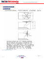
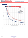
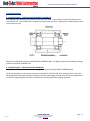
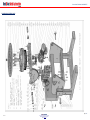
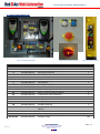
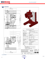
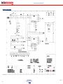
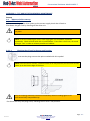
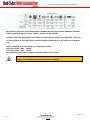
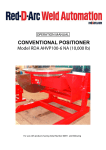
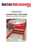
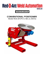
OPERATION MANUAL CONVENTIONAL POSITIONER Model RDA AHVP15-4 NA (1,500 lb) Conventional Positioner Model AHVP0.7 Contents 1.0 PREFACE ........................................................................................................................................ - 3 1.1 MACHINE SPECIFICATIONS ............................................................................................................. - 4 1.2 LOADING DATA .......................................................................................................................... - 4 1.3 LOADING CHART ........................................................................................................................ - 5 1.4 SPECIFICATION ........................................................................................................................... - 6 1.5 CE CERTIFICATE OF CONFORMITY ............................................................................................... - 7 1.6 UL/CAS LISTING INFORMATION .................................................................................................. - 8 2.0 INSTALLATION ............................................................................................................................... - 9 3.0 OPERATION ................................................................................................................................. - 11 3.1 Control Panel ........................................................................................................................... - 11 3.2 CONTROL PENDANT OPERATION .................................................................................................. - 12 3.3 ADJUSTING HEIGHT POSITION ...................................................................................................... - 13 4.0 MAINTENANCE ............................................................................................................................ - 15 4.1 MAINTENANCE - TAPER ROLLER BEARINGS & LOCKNUTS .......................................................... - 15 4.2 MAINTENANCE - PHOSPER BRONZE BEARINGS ......................................................................... - 15 4.3 MAINTENANCE - OPEN GEARS .................................................................................................. - 16 4.4 MAINTENANCE - EARTHING BRUSHES ....................................................................................... - 16 4.5 MAINTENANCE - ELECTRICAL MAINTENANCE ............................................................................ - 16 4.6 MAINTENANCE - CLEANLINESS / ENVIRONMENT....................................................................... - 16 4.7 MAINTENANCE - TIGHTNESS OF CONNECTIONS ........................................................................ - 17 4.8 MAINTENANCE - INSULATION ................................................................................................... - 17 4.9 MAINTENANCE – CONTROL GEAR ............................................................................................. - 17 5.0 REPLACEMENT PARTS .................................................................................................................. - 17 5.1 MECHANICAL ELECTRICAL PARTS .............................................................................................. - 18 5.2 ELECTRICAL PARTS LIST............................................................................................................. - 19 APPENDIX A - OVERVIEW DRAWING .................................................................................................. - 20 FIGURE 10 OVERVIEW DRAWING ....................................................................................................... - 20 APPENDIX B – WIRING DIAGRAM....................................................................................................... - 21 FIGURE 11 WIRING DIAGRAM ............................................................................................................ - 21 APPENDIX C – INVERTER DRIVE PARAMETER SETTINGS ...................................................................... - 22 APPENDIX A – TILT AND ROTATION GEARBOX MAINTENANCE ........................................................... - 23 A.1 Measures before startup ...................................................................................................... - 23 A.1.1 Oil level check .................................................................................................................. - 23 A.1.1.1 Checking the oil level in the gear unit housing ............................................................... - 23 A.1.1.2 Oil sight glass (Special feature) .................................................................................... - 24 A.1.1.3 Dipstick (Special feature) ............................................................................................... - 24 A.1.2 Startup without long term preservation ............................................................................ - 24 A.1.3 Startup in case of long term preservation ......................................................................... - 24 D.1.3.1 Long term preservation up to 18 months.................................................................... - 24 A.1.3.2 Long term preservation up to 36 months.................................................................... - 24 - A.1.4 Filling with lubricant ......................................................................................................... - 24 A.1.5 Drive with backstop .......................................................................................................... - 25 A.2 Maintenance and repair ....................................................................................................... - 26 A.2.1 General Information on Maintenance ............................................................................... - 26 A.2.2 Description of maintenance and repairs ............................................................................ - 27 Red D Arc Welderentals Version v1.0 667 South Service Rd., Grimsby, ON L3M 4G1 Phone: 905.643.4910 Efax: 905.963.7810 Website: reddarc.com Page - 2 - Conventional Positioner Model AHVP0.7 A.2.2.1 Perform oil change or oil flushing ....................................................................................... - 27 A.2.2.2 Clean vent plug ............................................................................................................ - 28 A.2.2.3 Clean the drive ............................................................................................................. - 28 A.2.2.4 Checking all fixing screws for tightness ........................................................................ - 28 A.2.2.5 Inspection of the drive ....................................................................................................... - 29 A.2.3 Lubricants......................................................................................................................... - 29 INDEX OF PICTURES ........................................................................................................................... - 31 INDEX ................................................................................................................................................ - 32 - 1.0 PREFACE This user’s manual describes the everyday use and maintenance of our Welding Positioners. Any actions that are required to be carried out by the manufacturer have not been included in this manual. This manual is part of the machine. Please keep this manual safe. Information in this manual could be useful at a later time or when a repair or maintenance is carried out. We suggest that a copy of the manual is made and kept with the machine; the original should be kept in a safe place. If necessary, replacement copies can be supplied. If the machine is sold at a later date then the manual should be also supplied with it to the new user. Red D Arc Welderentals Version v1.0 667 South Service Rd., Grimsby, ON L3M 4G1 Phone: 905.643.4910 Efax: 905.963.7810 Website: reddarc.com Page - 3 - Conventional Positioner Model AHVP0.7 1.1 MACHINE SPECIFICATIONS 1.2 LOADING DATA Figure 1 Loading Calculation Diagram Red D Arc Welderentals Version v1.0 667 South Service Rd., Grimsby, ON L3M 4G1 Phone: 905.643.4910 Efax: 905.963.7810 Website: reddarc.com Page - 4 - Conventional Positioner Model AHVP0.7 1.3 LOADING CHART Figure 2 Loading Chart `f Red D Arc Welderentals Version v1.0 667 South Service Rd., Grimsby, ON L3M 4G1 Phone: 905.643.4910 Efax: 905.963.7810 Website: reddarc.com Page - 5 - Conventional Positioner Model AHVP0.7 1.4 SPECIFICATION Load capacity Table diameter Degree of table tilting Degree of table rotation Table rotation speed Table tilting speed : : : : : : 700kgs @ 100mm eccentricity & 100mm C.O.G. 750mm 135o 360o 0-1.2 RPM 30 seconds through 135o Table machined with concentric circular markings and 4 off 15mm (19/32”) slots. Table equipped with efficient built in earthing, 300 amps, and mounted on pre-loaded cross-roll bearing. Table rotation fitted with AC motor and controlled by an inverter unit suitable for 110V 1 Phase 60Hz Supply. Tilting through inverter controlled AC electric motor equipped with limit switches to prevent over-run. Height Settings when table horizontal Position 1: 650mm Position 2: 750mm Position 3: 850mm Table can be manually elevated from the base, and locked into position using one of the three pin locations. The main control panel mounted on the machine containing the following, mains isolator, mains on lamp, emergency stop button and reset button. The positioner is also supplied with a low voltage remote pendant control containing forward/stop/reverse, tilt-up/tilt-down pushbuttons and a variable speed potentiometer for table rotation speed. Connected with 8 meters of cable to the control panel. Mains electrical supply suitable for 110V 1 Phase 60Hz. Red D Arc Welderentals Version v1.0 667 South Service Rd., Grimsby, ON L3M 4G1 Phone: 905.643.4910 Efax: 905.963.7810 Website: reddarc.com Page - 6 - Conventional Positioner Model AHVP0.7 1.5 CE CERTIFICATE OF CONFORMITY Machine Type 0.7T Welding Positioner Model AHVP0.7 We hereby certify that the above machine has been manufactured by Key Plant Automation Limited, and conforms to the essential requirements of the following E. U. Directives; Supply of machinery (Safety) Regulations implementing the EC Machinery Directive 89/392/EEC amended 91/368/EEC and 93/44/EEC and 93/68/EEC codified to 98/37/EC. 73/23 EEC Low Voltage Directive amended by the directive 93/68 EEC regarding safety of electrical equipment. 89/336 EEC Electro-Magnetic Compatibility amended by directives 92/31 EEC and 93/68 EEC. As implemented by the UK. Supply of Machinery (Safety) Regulations 1992. Authorised signatory Steve Piercy Engineering Manager Red D Arc Welderentals Version v1.0 667 South Service Rd., Grimsby, ON L3M 4G1 Phone: 905.643.4910 Efax: 905.963.7810 Website: reddarc.com Page - 7 - Conventional Positioner Model AHVP0.7 1.6 UL/CAS LISTING INFORMATION Red D Arc Welderentals Version v1.0 667 South Service Rd., Grimsby, ON L3M 4G1 Phone: 905.643.4910 Efax: 905.963.7810 Website: reddarc.com Page - 8 - Conventional Positioner Model AHVP0.7 2.0 INSTALLATION Red D Arc Welderentals Version v1.0 667 South Service Rd., Grimsby, ON L3M 4G1 Phone: 905.643.4910 Efax: 905.963.7810 Website: reddarc.com Page - 9 - Conventional Positioner Model AHVP0.7 Remove transport protection (if any) from the machine. Locate the machine on a level floor that is capable of withstanding approximately 2.5 tonnes over the contact area. Connect the electrical mains to the machine, 110V, 1Phase, 60Hz. Connect the welding earth cable to the copper earthing strip that is located on the underside of the table, fixed to the crosshead. If this connection is NOT made the weld current will earth through the centre of the table assembly and damage the bearings and other transmission parts. (See photo below for earthing connection bracket) Earth Cable Connection Figure 3 Photo of Earthing Point Before making the machine fully operational, remove any necessary covers and check that the gearboxes have not lost any lubrication during transport. Red D Arc Welderentals Version v1.0 667 South Service Rd., Grimsby, ON L3M 4G1 Phone: 905.643.4910 Efax: 905.963.7810 Website: reddarc.com Page - 10 - Conventional Positioner Model AHVP0.7 3.0 OPERATION 3.1 Control Panel 1 2 The control panel at the rear of the positioner has the following controls; 1. Power On Lamp 2. Emergency Stop Reset Button – After an Emergency Stop or when first powering up, this button must be pressed, before the machine will operate. Once pressed and the machine is ready the button will illuminate. 3. Emergency Stop Button 4. Panel door opening key 5. Door electrical isolator, must be turned off before panel door can open. 3 4 5 Figure 4 Main Panel Red D Arc Welderentals Version v1.0 667 South Service Rd., Grimsby, ON L3M 4G1 Phone: 905.643.4910 Efax: 905.963.7810 Website: reddarc.com Page - 11 - Conventional Positioner Model AHVP0.7 3.2 CONTROL PENDANT OPERATION It is imperative when loading the machine that the fabrication is held firmly on the table, using the table slots provided. It is also important that the machine is NOT OVERLOADED by placing on it fabrications which are heavy or are beyond the capacity of the machine in terms of Centre of Gravity or Eccentricity. Once the machine has power connected and the “power on” light is illuminated. The machine will be ready to run. If the emergency stop button has been depressed then release this by twisting the cap, then press the emergency stop reset button on the control box. Speed and movement of the positioner are controlled by the hand pendant, (see photo below). The buttons on the pendant operate as follows BUTTON A Hold to Run Push Button Tilt UP BUTTON B Hold to Run Push Button Tilt Down BUTTON C Table Rotation Reverse Direction Push Button Button A B BUTTON D BUTTON E Table Rotation Stop Push Button Table Rotation Forward Direction Push DIAL F BUTTON G Rotation Speed Potentiometer Emergency Stop Push Button C D E F G Figure 5 Hand Control Pendant Red D Arc Welderentals Version v1.0 667 South Service Rd., Grimsby, ON L3M 4G1 Phone: 905.643.4910 Efax: 905.963.7810 Website: reddarc.com Page - 12 - Conventional Positioner Model AHVP0.7 3.3 ADJUSTING HEIGHT POSITION The positioner can be set at one of three height positions. To alter the height of the machine please follow this simple procedure. First loosen off bolts D (2 on either side of the machine), this will release the table section so that it can be lifted. Then connect a crane to the lifting eyes on either side of the machine (A). Take up the slack on the lifting eyes so the weight is taken by the crane, then the lock pins (B) on either side of the positioner can be removed. A C D B The table can then be raised or lowered by using the crane, so that hole C lines up with the lock pin (B) holes. Pin B on both sides of the machine can then be replaced. Once pins B are fully in place on both sides, then the weight of the table can be taken by the pins and the crane removed. Tighten the 4 bolts D (2 on either side of the machine), this will prevent any movement of the positioner inside the height adjustment sleeve. Red D Arc Welderentals Version v1.0 667 South Service Rd., Grimsby, ON L3M 4G1 Phone: 905.643.4910 Efax: 905.963.7810 Website: reddarc.com Page - 13 - Conventional Positioner Model AHVP0.7 Note the vertical leg (with holes C through), is designed to sit flush, metal on metal at the top rear and bottom front of the sleeve (see pictures above). These areas are designed to take the weight of the machine. The bolts (D) are there to close the gap at the top front and bottom rear of the sleeve, so that there is no movement of the position in the sleeve. Red D Arc Welderentals Version v1.0 667 South Service Rd., Grimsby, ON L3M 4G1 Phone: 905.643.4910 Efax: 905.963.7810 Website: reddarc.com Page - 14 - Conventional Positioner Model AHVP0.7 4.0 MAINTENANCE 4.1 MAINTENANCE - TAPER ROLLER BEARINGS & LOCKNUTS Self aligning roller bearings are present to give zero end float. In time due to wear and vibration they may slacken off. They should then re-tighten to regain zero end float. Adjustment is obtained by means of the two lock nuts. Figure 6 Roller Bearing Replenish at 500 hour intervals with CASTROL SPHEEROL MP3. For high temperature conditions change grease to CASTROL SPHEEROL B3. 4.2 MAINTENANCE - PHOSPER BRONZE BEARINGS Replenish at 500 hour intervals be means of grease nipples using CASTROL SPHEEROL MP3. All of the phosphor bronze bushes used are retained with LOCTITE 601 bush retaining fluid. Any bush which becomes displaced should be carefully removed, thoroughly cleaned with the correct application of LOCTITE degreasing fluid and then coated with retaining fluid before being replaced. Red D Arc Welderentals Version v1.0 667 South Service Rd., Grimsby, ON L3M 4G1 Phone: 905.643.4910 Efax: 905.963.7810 Website: reddarc.com Page - 15 - Conventional Positioner Model AHVP0.7 4.3 MAINTENANCE - OPEN GEARS All gears are liberally coated with grease, CASTROL MS3 [molybdenum disulphide]. At 500 hour intervals remove safety guards and check coating, and if required replenish grease. 4.4 MAINTENANCE - EARTHING BRUSHES All rotary tables that are used for manipulating components to be welded are fitted with Earthing Brush’s to carry welding current away from the machines rotating axis to a suitable pickup point. IT IS MOST IMPORTANT TO CONNECT AN EARTHING CABLE TO THE MACHINES PICKUP POINT AND NOT TO EXCEED THE MAXIMUM RATING STATED. OTHERWISE SERIOUS DAMAGE CAN OCCUR TO MACHINES ROTATING AND ELECTRICAL PARTS. 4.5 MAINTENANCE - ELECTRICAL MAINTENANCE It is the responsibility of the user to ensure only competent personnel deal with the operation and maintenance of the equipment. Operators should be conversant with the equipment and be able to recognise the symptoms maloperation and/or degraded performance. They should also be aware of what action to take in the event of a fault/emergency. It is recommended that maintenance personnel have adequate training on the system and also the component parts. They should have a thorough knowledge of diagnosis and fault finding techniques and be conversant with identifying the first signs of mal-operation. During maintenance/fault finding etc, the following points should be observed The equipment should be completely isolated whenever possible. If an element of live diagnosis is required the use of barriers/warning notices is a must. The maintenance staff should be familiar with the appropriate factory and safety regulations that apply in the province and country that they are employed in, and work on the equipment is such a manner as to comply with them. The period between specific maintenance tasks will vary dependant on such factors as type of equipment and environment of the equipment. These factors should be assessed by the respective maintenance staff and maintenance periods adjusted accordingly. Maintenance should include attention to the points listed below: 4.6 MAINTENANCE - CLEANLINESS / ENVIRONMENT It is essential that the cubicle interior remains clean and dry. Any ingress of moisture or dirt should be cleaned with a lint free cloth or suitable suction device. Fans and filters should be checked regularly for blockages and dirty filter mats should be replaced with the correct grade of mat. Red D Arc Welderentals Version v1.0 667 South Service Rd., Grimsby, ON L3M 4G1 Phone: 905.643.4910 Efax: 905.963.7810 Website: reddarc.com Page - 16 - Conventional Positioner Model AHVP0.7 4.7 MAINTENANCE - TIGHTNESS OF CONNECTIONS It will be necessary to periodically check the tightness of terminals and bus-bar connections including earth connections, especially in areas where vibration is apparent. Check for any hot spots developing during running. Checks should be performed with the power supply isolated. 4.8 MAINTENANCE - INSULATION A visual check of cable/control gear insulation should be performed at regular intervals. If this inspection reveals any change in appearance an insulation resistance measurement is recommended. For older equipment these measurements should be taken on a more regular basis where successive lower readings would indicate a problem. NOTE: It is important to use insulation testing equipment with care. Electronic components should be securely isolated before employing meggers or similar test methods. 4.9 MAINTENANCE – CONTROL GEAR A visual inspection should be performed at regular intervals. Movements should be checked for free and unobstructed operation. This is very important for critical safety components (Emergency Stop Pushbuttons and Relays). 5.0 REPLACEMENT PARTS Use only parts as detailed by the supplier. Failure to do so could impair safety of equipment/personnel, or impair machine operation or the design of the equipment. Red D Arc Welderentals Version v1.0 667 South Service Rd., Grimsby, ON L3M 4G1 Phone: 905.643.4910 Efax: 905.963.7810 Website: reddarc.com Page - 17 - Conventional Positioner Model AHVP0.7 5.1 MECHANICAL ELECTRICAL PARTS Red D Arc Welderentals Version v1.0 667 South Service Rd., Grimsby, ON L3M 4G1 Phone: 905.643.4910 Efax: 905.963.7810 Website: reddarc.com Page - 18 - Conventional Positioner Model AHVP0.7 5.2 ELECTRICAL PARTS LIST 13 2 1 1 9 17 1 10 11 15 18 12 9 Figure 7 Control Panel Interior Photo Number 1 2 3 4 5 6 7 8 9 10 11 12 13 14 15 16 17 Part Number KPVP0075801UL KPVP0075802UL KPVP0075803UL KPVP0075804UL KPVP0075805UL KPVP0075806UL KPVP0075807UL KPVP0075808UL KPVP0075809UL KPVP0075810UL KPVP0075811UL KPVP0075812UL KPVP0075813UL KPVP0075814UL KPVP0075815UL KPVP0075816UL KPVP0075817UL 18 19 Not Shown KPVP0075818UL KPVP0075819UL KPVP0075820UL Figure 8 Control Panel Exterior Description Inverter Drive (Rotation) 1 Phase 0.75kW Contactor Reversing Contactor 1 Pole Circuit Breaker 10A 1 Pole Circuit Breaker 2A 1 Pole Circuit Breaker 3A Fuse Holder 10 Way Earthing Bar Fused Door Isolator Terminals (Grey) Earth Terminals (Green/Yellow) Transformer 415V:24V 63VA Mains Power On Lamp Emergency Stop Reset Blue Pushbutton Emergency Stop Button Pendant Housing Pendant Push Buttons (Red, Green, Yellow, Black, White) Speed Potentiometer Pendant Emergency Stop Button Pendant Cable Red D Arc Welderentals Version v1.0 16 456 7 3 8 14 667 South Service Rd., Grimsby, ON L3M 4G1 Phone: 905.643.4910 Efax: 905.963.7810 Website: reddarc.com 19 Figure 9 Control Pendant Quantity 2 1 1 1 1 1 2 1 1 22 4 1 1 1 1 1 5 1 1 8m Page - 19 - Conventional Positioner Model AHVP0.7 APPENDIX A - OVERVIEW DRAWING FIGURE 10 OVERVIEW DRAWING Red D Arc Welderentals Version v1.0 667 South Service Rd., Grimsby, ON L3M 4G1 Phone: 905.643.4910 Efax: 905.963.7810 Website: reddarc.com Page - 20 - Conventional Positioner Model AHVP0.7 APPENDIX B – WIRING DIAGRAM FIGURE 11 WIRING DIAGRAM Red D Arc Welderentals Version v1.0 667 South Service Rd., Grimsby, ON L3M 4G1 Phone: 905.643.4910 Efax: 905.963.7810 Website: reddarc.com Page - 21 - Conventional Positioner Model AHVP0.7 APPENDIX C – INVERTER DRIVE PARAMETER SETTINGS The following settings have been programmed into the inverter at the factory; Tilt Drive: Parameter Number 1 2 3 4 5 6 7 8 9 10 Value 50 50 0.1 0.1 AI.AV 3 1680 230 0.85 L3 Parameter Number 11 12 22 39 46 48 49 50 51 Value 0 Rel A 60 0 0 0 0 0 All other values are as factory set by the inverter manufacturer and need not be altered. Rotation Drive: Parameter Number 1 2 3 4 5 6 7 Value 2.5 70 1 1 AI.AV 2.9 1680 Parameter Number 8 9 10 11 22 39 42 Value 230 0.85 L3 1 A 60 5 All other values are as factory set by the inverter manufacturer and need not be altered. Red D Arc Welderentals Version v1.0 667 South Service Rd., Grimsby, ON L3M 4G1 Phone: 905.643.4910 Efax: 905.963.7810 Website: reddarc.com Page - 22 - Conventional Positioner Model AHVP0.7 APPENDIX A – TILT AND ROTATION GEARBOX MAINTENANCE Startup A.1 Measures before startup A.1.1 Oil level check Before connecting up the drive system to the current supply check the oil level or Shut down the gear unit by shutting off the drive unit ! A.1.1.1 WARNING! Secure drive unit to prevent accidental start-up. Affix notice at the switchon point. Note: In case of tandem gear units, each single gear unit should be inspected separately. Check oil level with the oil cooled down. Even after a short run, oil needs a longer ‘rest’ in order to release possible air bubbles. Checking the oil level in the gear unit housing Screw out the plug screw at the point marked with this symbol. Note: If the oil level is correct, a small amount of oil may flow out; the oil must at least come up to the lower edge of the bore. ! Any oil escaping should be removed immediately with oil binding agent in an environmentally compatible way. For drives with only one plug screw, checking the oil level is not possible. Red D Arc Welderentals Version v1.0 667 South Service Rd., Grimsby, ON L3M 4G1 Phone: 905.643.4910 Efax: 905.963.7810 Website: reddarc.com Page - 23 - Conventional Positioner Model AHVP0.7 A.1.1.2 Oil sight glass (Special feature) If an oil inspection glass is provided, the oil level must be visible in the middle of the inspection glass. A.1.1.3 Dipstick (Special feature) Check oil level with dipstick: The oil level must be between the lower and upper mark of the dipstick. A.1.2 Startup without long term preservation MOTOX® drives are delivered with the appropriate lubricants ready for operation depending on the specified conditions of use. ! On gear systems with the required housing ventilation the required ventilator filter is delivered loose with the unit. It must be replaced with the appropriate screw plug before the initial start –up of the gear unit. It must be used at the position indicated by this symbol. A.1.3 Startup in case of long term preservation D.1.3.1 Long term preservation up to 18 months ! Before starting up the gear unit, it should be filled with lubricant (see D.1.4). A.1.3.2 Long term preservation up to 36 months ! The gear unit is completely filled with oil. Before the start up, the oil level should be corrected according to the type of construction. The oil level should be reduced to the level marked with this symbol (see D.1.1). ! Any oil escaping should be removed immediately with oil binding agent in an environmentally compatible way. A.1.4 Filling with lubricant Screw out venting screw or venting filter or plug screw at the highest point (see 3.2 or point of ventilation). Red D Arc Welderentals Version v1.0 667 South Service Rd., Grimsby, ON L3M 4G1 Phone: 905.643.4910 Efax: 905.963.7810 Website: reddarc.com Page - 24 - Conventional Positioner Model AHVP0.7 ! Fill gear unit up with fresh oil using a filling filter (max. filter coarseness 60 µm). The quantity of oil depends on the mounting position! Note: Recommendations on the oil to be used should be taken from section 10. “Maintenance and repair.” Data, such as oil grade, oil viscosity and oil quantity required will be found on the rating plate Finally, check the oil level (see 7.1.1). ! Any oil escaping should be removed immediately with oil binding agent in an environmentally compatible way. A.1.5 Drive with backstop ! ! Secure drive unit to prevent accidental start-up. Affix notice at the switch-on point. Check the direction of rotation before putting into service! E.g. by manually turning the input shaft or the motor. Check the motor direction of rotation according to the phase sequence, swap two supply leads if necessary. Red D Arc Welderentals Version v1.0 667 South Service Rd., Grimsby, ON L3M 4G1 Phone: 905.643.4910 Efax: 905.963.7810 Website: reddarc.com Page - 25 - Conventional Positioner Model AHVP0.7 A.2 Maintenance and repair A.2.1 General Information on Maintenance ! All maintenance and repair work should be carried out with due care and only by thoroughly trained personnel. The periods listed in the table below, are largely dependent on the conditions of use of use of the gear unit. For this reason, it is only possible to give average periods which refer to a - Daily operating time of Duty factor of Input drive speed of Max. Oil temperature of 24 h ED 100% 1500 min-1 100oC NOTE: Under different operating conditions, the periods should be adjusted accordingly. Measures Observe/check gear unit noise for changes Observe/check oil temperature Oil level check Check gear unit for leakage Initial oil change after startup Subsequent oil changes Clean vent plug Clean drive Causes from time to time, more often during operation if possible from time to time, more often during operation if possible monthly monthly after approx. 10000 operating hours, at the latest after 3 years every 3 years or 10000 operating hours every 3 months according to the degree of contamination at least once a year Check all fixing screws for tightness Carry out complete inspection of at least once a tear gear unit Red D Arc Welderentals Version v1.0 667 South Service Rd., Grimsby, ON L3M 4G1 Phone: 905.643.4910 Efax: 905.963.7810 Website: reddarc.com Remedy see D.1.1 see D.2.2.1 see D.2.2.1 see D.2.2.2 see D.2.2.3 see D.2.2.4 see D.2.2.5 Page - 26 - Conventional Positioner Model AHVP0.7 A.2.2 Description of maintenance and repairs A.2.2.1 Perform oil change or oil flushing $ NOTE: Different types of oil must not be mixed. Types of oil: - mineral oil (CLP oil DIN 51517/3) - synthetic oil with a specific base (PGLP-Öl) Specifications like oil type, oil viscosity and required oil quantity are shown on the name plate. $ Oil change and oil flushing: If using the same type of oil are before, use only that oil. If using a new oil type, use only the new type. Thoroughly remove oil sludge, abraded material and used oil residue from the housings by oil flushing. $ High-viscosity oils must be warmed beforehand. The oil should be drained off after shutdown, while the gear unit is still warm. Shut down the gear unit by shutting off the drive unit. ! Secure drive unit to prevent accidental start-up. Affix notice at the switch-on point. 1. Place a suitable collection receptacle under the oil drain plug of the gear unit housing. 2. Unscrew vent plug on the upper side of the housing. 3. Unscrew oil drain plug and drain oil off into the receptacle. ! There is a risk of scalding from the hot oil emerging. Wear protective gloves. 4. Screw in oil drain plug. Note: Check condition of seal ring, use new seal ring if necessary. 5. Filling with lubricant see D.1.4 6. Screw vent plug on the upper side of the housing. Red D Arc Welderentals Version v1.0 667 South Service Rd., Grimsby, ON L3M 4G1 Phone: 905.643.4910 Efax: 905.963.7810 Website: reddarc.com Page - 27 - Conventional Positioner Model AHVP0.7 A.2.2.2 Clean vent plug The vent plug must be cleaned after deposit of a dust layer – at least every 3 months. For this the filter must be unscrewed, flushed out with cleaning benzene or a similar cleaning agent and dried or blown through with compressed air. I Ensure adequate ventilation. Do not inhale vapours. Do not smoke. Explosion hazard. A.2.2.3 Clean the drive Shut down the gear unit by shutting off the drive unit. ! Secure drive unit to prevent accidental start-up. Affix notice at the switch-on point. Keep drives free of dirt and dust, etc in order to ensure sufficient heat dissipation. Cleaning the drive with a high-pressure cleaning device is not permissible. Do not use sharp-edged tools. A.2.2.4 Checking all fixing screws for tightness Shut down the gear unit by shutting off the drive unit. ! Secure drive unit to prevent accidental start-up. Affix notice at the switch-on point. Check all fixing screws for tightness with a torque wrench Thread size Tightening torque M6 10 Nm M8 25 Nm M 10 50 Nm M 12 90 Nm M 16 210 Nm M 20 450 Nm M 24 750 Nm M 30 1500 Nm M 36 2500 Nm Property class min. 8.8 Note: Unserviceable screws should be replaced by new ones of the same property class and type. Red D Arc Welderentals Version v1.0 667 South Service Rd., Grimsby, ON L3M 4G1 Phone: 905.643.4910 Efax: 905.963.7810 Website: reddarc.com Page - 28 - Conventional Positioner Model AHVP0.7 A.2.2.5 Inspection of the drive The drive should be checked annually In addition, the drive should be checked according to the criteria described in section 2. “Safety notes,” e.g. check tight fit of the protective devices. Any damage of the coating should be repaired by an expert. A.2.3 Lubricants Oil selection should always be determined by the oil viscosity (ISO VG class) specified on the rating plate of the gear unit. The viscosity class is valid for the operating conditions agreed on by contract. Under different operating conditions, it will be necessary to consult us. We have put together a list of suitable lubricants for the gear unit in the table below. We are acquainted with the composition of these lubricants and know that in accordance with the latest technology, they possess values in respect of loadability, corrosion protection, load carrying capacity with micro-pitting, as well as compatibility with seals and internal coating on which the design of the gear unit has been based. Thus we recommend that our customer should select a lubricant from this table, taking in account the viscosity class stated on the rating plate. The lubricants listed have no approval according to USDA –H1/-H2 (United States Department of Agriculture) and are as such not, or only limited approved, for use in the food or pharmaceutical industry. The lubricants are not or only limited biologically decomposable. They are usually according to the Classes 2 or 1 of hazard for water. If lubricants are necessary according to these classifications, please contact the factory. If the gearboxes are filled with special lubricants from the factory for the cases given above, this can be seen on the name plate e.g. CLP-H1 VG220 or CLP E VG220. Note: As a precaution against misunderstandings, we would like to point out that the recommendation does not imply any release in the sense of a warranty for the quality of the lubricant provided by your supplier. Each lubricant manufacturer must warrant the quality of his product himself. If you do not follow our recommendations, you must take the responsibility for the technical suitability of the lubricant. In the case of synthetic oils not listed in the table below, the corrosiveness of the oil to our internal coating should be checked. A check of this nature is carried out by us at cost (cost on request) Red D Arc Welderentals Version v1.0 667 South Service Rd., Grimsby, ON L3M 4G1 Phone: 905.643.4910 Efax: 905.963.7810 Website: reddarc.com Page - 29 - Conventional Positioner Model AHVP0.7 We would be pleased to recommend further suitable lubricants of the makes ADDINOL, CASTROL, FUNCHS Lubritech, OMV, STATOIL, TEXACO, TUNAP and VALVOLINE. Synthetic lubricants (polyglycols) in accordance with designation PGLP as per DN51 502. These oils are distinguished by their high aging resistance and favourable effect on the efficiency of the gear unit. They are suitable for the following operating temperatures: PGLP ISO VG 220: -30c ... +100c PGLP ISO VG 460: -15c ... +100c The maximum temperatures can be exceeded by 10K for a short time. $ Note: If operating temperature of the drive exceeds or undershoots the limit valves, the oil selected should be checked for suitability. Red D Arc Welderentals Version v1.0 667 South Service Rd., Grimsby, ON L3M 4G1 Phone: 905.643.4910 Efax: 905.963.7810 Website: reddarc.com Page - 30 - Conventional Positioner Model AHVP0.7 INDEX OF PICTURES Figure 1 Loading Calculation Diagram ...................................................................................................... - 4 Figure 2 Loading Chart .............................................................................................................................. - 5 Figure 3 Photo of Earthing Point ............................................................................................................ - 10 Figure 4 Main Panel ................................................................................................................................ - 11 Figure 5 Hand Control Pendant .............................................................................................................. - 12 Figure 6 Roller Bearing............................................................................................................................ - 15 Figure 7 Control Panel Interior ............................................................................................................... - 19 Figure 8 Control Panel Exterior............................................................................................................... - 19 Figure 9 Control Pendant ........................................................................................................................ - 19 Figure 10 Overview Drawing .................................................................................................................. - 20 - Red D Arc Welderentals Version v1.0 667 South Service Rd., Grimsby, ON L3M 4G1 Phone: 905.643.4910 Efax: 905.963.7810 Website: reddarc.com Page - 31 - Conventional Positioner Model AHVP0.7 INDEX C CE CERTIFICATE, - 7 -, - 8 Centre of Gravity, - 12 CLEANLINESS / ENVIRONMENT, - 16 Contents, - 2 CONTROL GEAR, - 17 - O OPEN GEARS, - 16 OPERATION, - 11 - P E earthing, - 10 EARTHING, - 16 Eccentricity, - 12 ELECTRICAL PARTS LIST, - 18 -, - 19 - Panel, - 11 -, - 12 -, - 13 Preface, - 3 - R Replacement Parts, - 17 - S F slots, - 12 SPECIFICATIONS, - 4 - Forward, - 12 - G gearbox, - 10 Gearbox Maintenance, - 22 -, - 23 - I T TAPER ROLLER BEARINGS & LOCKNUTS, - 15 TIGHTNESS OF CONNECTIONS, - 17 Tilt Up, - 12 - U INSTALLATION, - 9 INSULATION, - 17 UL/CAS, - 8 - L LOADING CHART, - 5 LOADING DATA, - 4 lubricants, - 24 -, - 29 -, - 30 - V Variable Speed Potentiometer, - 12 -, - 14 - M W wiring diagram, - 21 - MAINTENANCE, - 15 - Red D Arc Welderentals Version v1.0 667 South Service Rd., Grimsby, ON L3M 4G1 Phone: 905.643.4910 Efax: 905.963.7810 Website: reddarc.com Page - 32 -