Transcript
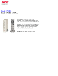
User's Guide
Continuity Tester Pro
Model CT20
Introduction
Congratulations on your purchase of the Extech CT20 Continuity Tester Pro.
The CT20 allows a single user to quickly identify and label two wires even
when the wire ends are located in different rooms. This tester is shipped fully
tested and with proper use will provide years of reliable service.
Safety
CAUTION: DO NOT CONNECT TO A LIVE CIRCUIT
Operation
CAUTION: DO NOT CONNECT TO LIVE WIRES.
Use only on non-energized circuits
Remote Continuity
Remote continuity is a different mode of usage for the Tester and requires the
Remote Probe. This mode is primarily used for: A. remote verification of continuity
for cable/wires, or
B. individual cable/wires for identification and labeling. Properly used, the Tester
with Remote Probe will eliminate numerous trips when testing cable TV, electrical
cables, and speaker/telephone wiring in multi-room/multi-floor installations.
1.
Turn power on. The green power LED
will glow. If green LED fails to light
replace 9V battery.
2.
Attach red and black alligator clips of
Tester to one end of cable/wires
under test.
3.
Proceed to the other end of the
cable/wires and connect them to
Remote Probe test leads.
4.
If continuity exists, the LED on the
probe will flash either green or red
depending on the Probe leads
orientation. Note: At this point, Tester
hanging on cable/wires at origination end will beep and flash
red while remote probe (with user) at destination end is
verifying continuity.
Safety Precautions
1.
2.
3.
4.
Improper use of this tester can cause damage, shock, injury or death.
Read and understand this user’s guide before use.
Ensure that the battery door is properly closed and secured before use.
Inspect the condition of the test leads and the tester itself for any damage
before use.
Remove the battery from the tester if it is to be stored for a long period.
Description
1.
2.
3.
4.
5.
6.
7.
8.
9.
10.
Local Continuity Tester (main pulsing unit)
Local Continuity Indicator (flashing
red LED)
Power On/Off (mini-slide switch)
Power “On” Indicator (steady green
LED)
Local Continuity Beeper (with air
holes on rear of case)
Remote Probe Continuity Indicator
(red/green bi-color LED)
Remote Probe Holder (side
mounted plastic piece)
Red and Black Remote Probe Leads
w/alligator clips
Red and Black Tester Leads w/alligator
9 Volt Battery Compartment (removable cover on rear)
Specifications
Power supply
Beeper
Battery life
Continuity confirmation
Continuity drive current:
9 Volt Battery
85dB beeper
Approx. 12 months with normal use.
Equal to or less than 2.0 K Ohms
Pulsed (2.0 Hz) 20 - 50mA at 10 Ohms and 2.0mA 8.0mA at 1000 Ohms.
Wire Verification Distance 10,000 ft., 3,000 m (26 Gage min.)
Fuse
250V 0.5A fast blow
Operating Temperature
-12 to 45oC (10oF to 113oF)
Storage Temperature
-20 to 80oC (-4 to 176oF)
Operating Humidity
10 to 90% RH (non-condensing)
Dimensions
90 x 57 x 29mm (3.6 x 2.2 x 1.14”)
Weight
260g (9.2oz)
5.
6.
When Tester (red lead) is connected through wire under test
to Remote Probe (red lead) and Tester (black lead) is
connected through wire under test to Remote Probe (black
lead), then Probe LED flashes green indicating correct
connection orientation. If Probe LED flashes red, this
indicates Probe Leads are not correctly connected. Reverse
probe leads to produce green light.
Once correct orientation has been achieved (flashing
green LED), then wires under test can be labeled
consistent with the colors on tester and probe leads.
Local Continuity
Using just the tester (without probe) you
can easily test any in-wall wiring from point
to point locations in the same room. Other
handy uses are to quickly test light bulbs,
fuses, switches, relay contacts, diodes, low
ohm power resistors, circuit breakers, etc.
for electrical continuity.
1. Turn power switch on. The green
power LED will glow. If green LED
does not light, replace 9V battery.
2. To check same room wiring runs, attach both red and black alligator clips of
Tester to both wires on one end of multi-wire cable under test and let Tester
hang from wires.
3. Go to other end of same cable and momentarily connect wires in cable
together. The Tester will beep and red LED will flash indicating continuity.
4. When continuity is found, label both ends of cable with the same number or
name.
5. To test other devices (listed above) connect Tester leads to device terminals in
any* lead orientation (red or black). If device makes internal electrical
connection then Tester will beep and its red LED will flash indicating continuity.
*Exception: When testing a diode, the red Tester lead is positive and will show
continuity when connected to the anode (positive (+) side) with black Tester lead
to cathode (negative (-) side).
Battery replacement
1.
2.
3.
Loosen Phillips head screw of battery compartment and remove cover
(rear).
Replace 9 volt battery and compartment cover and then tighten screw.
Never dispose of used batteries or rechargeable
batteries in household waste.
As consumers, users are legally required to take used
batteries to appropriate collection sites, the retail store
where the batteries were purchased, or wherever
batteries are sold.
Disposal: Do not dispose of this instrument in household waste. The
user is obligated to take end-of-life devices to a designated collection
point for the disposal of electrical and electronic equipment.
Advanced Remote Continuity and Wire
Identification
The Remote Continuity mode can be used to check continuity and to identify two,
three or more cables/wires simultaneously by applying simple logic and a testing
strategy. To facilitate cable/wire identification, the leads of the tester and probe use
matching color
Other Battery Safety Reminders
o Never dispose of batteries in a fire. Batteries may explode or
leak.
o Never mix battery types. Always install new batteries of the same
type.
Copyright © 2013‐2015 FLIR Systems, Inc. All rights reserved including the right of reproduction in whole or in part in any form ISO‐9001 Certified www.extech.com CT20-en-GB_v4.3 4/15