1
R&S®DST200
RF Diagnostic Chamber Features
Configuring a Test PC
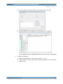
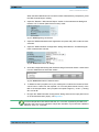
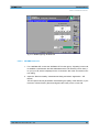
c) Open the dialog box to define the characteristics of the device by double-clicking
on it.
In the "Properties" tab, select "Standard Turntable" as the device type. Set the
"Tolerance" to 1 and "Acceleration" to 4.
d) In the "Device List", register a second "DST200 Positioner" device from the device
class "TurnTables" and rename it to "DST200 Elevation Positioner".
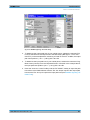
In the "Properties" tab, select "Mobile Phone Positioner" as the device type. Set
the "Tolerance" to 1 and "Acceleration" to 4.
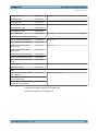
e) In the "General" tab, select "COM1" as the "Interface Type" for both positioners
("DST200 Azimuth Positioner" and "DST200 Elevation Positioner").
The RS232 cable of R&S DST-B16x shall be connected to the COM interface of
the Test PC. Change the number of the COM interface if necessary.
f) Connect the RS232 cable.
User Manual 1515.1421.02 ─ 03
32