1
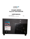
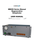
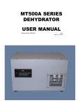
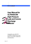
MR050A SERIES
DEHYDRATOR
USER MANUAL
Bulletin AE01B-A0532-001
Rev: B
© 2008 - 2011CommScope, Inc. All rights reserved(04/11)
MR050A SERIES DEHYDRATOR USER MANUAL
SECTION 1
General Information
Introduction
Description
Operation
Alarms Option
Multiple Alarm Option
Specifications
3
3
3
3
3
4
5
SECTION 2Installation
Unpacking and Inspection
Controls and Displays
Power Connections
AC Power
DC Power
Connecting Low Pressure Alarm Output
Connecting Dehydrator to the Transmission Line
Purging the Transmission Line
6
6
6
7
7
7
8
8
9
SECTION 3Maintenance
Maintenance
Preventive Maintenance
Desiccant Replacement
Annual Maintenance
Parts Replacement
Service Restoration
9
9
9
9
9
9
10
SECTION 4Troubleshooting
11
Problem/Solution Table
11
Schematic Diagram MR050A-3101513
Alarm Schematic Diagram with All Option MR050A-3131515
Pneumatic Diagram16
SECTION 5
Replacement Parts
17
SECTION 6
Customer Service
17
Introduction17
In Case of Trouble
17
Initial Steps by CommScope
18
Return Goods Instructions
18
Repair Center Process
18
Loaner Units
18
Warranty
19
2
MR050A SERIES DEHYDRATOR USER MANUAL
1.1
Introduction
This manual contains the information you need
to install, operate, and maintain your MR050A
Series DryLine® dehydrator. Please take the
time to read this manual before attempting to
operate or service the unit.
1.2
Description
MR050A Series dehydrators provide dry air for
pressurizing small (up to 280 liters, or 10 cubic
feet, in volume) antenna and transmission line
systems. The dehydrators produce -40ºC (-40ºF)
dew point dry air at a nominal rate of 1.4 liters
(0.05 cubic feet) per minute up to a total of 8495
Iiters (300 cubic feet) on a single desiccant
canister.
Each dehydrator consists of an electricallydriven air compressor, a desiccant canister, an
automatic transmission line pressure sensing
system, and alarm outputs housed in a rigid
metal chassis. It is designed to mount directly to
the rack, directly on a wall, or as a free-standing
unit. The front panel features a control interface
with display for alarms and pressure. For easy
serviceability, power connections, alarm output
connections, and the desiccant canister are
easily accessible from the front of the unit.
The MR050A maintains transmission line
pressures between 2.0 and 3.4 kPa (0.3 and
0.5 psig). It is intended for use with high
performance microwave antennas and earth
station antennas.
1.3
Operation
MR050A series dehydrators include a
compressor, color indicating desiccant, high and
low-pressure sensors, and a low-pressure alarm
sensor.
.
3
When system pressure falls to a preset low
limit, the low-pressure sensor activates the
compressor. Air is channeled through a
desiccant canister, where moisture is adsorbed.
The air exits the drying canister at -40°C (-40°F)
dewpoint. It is then channeled directly to an
internal 4-port manifold
When system pressure reaches a preset high
limit, the high-pressure sensor shuts off the
compressor. A check valve prevents system dry
air from retreating back through the compressor.
If system pressure falls significantly below the
low-pressure trigger point, the low-pressure
alarm sensor will activate an alarm contact.
This alarm is an indication of a significant
system leak or a dehydrator failure.
1.4
Alarms
The MR050A offers Low Pressure and Power
Fail alarms as a standard feature. Alarm
conditions are indicated on the display. Alarms
are output as a common summary alarm,
with a form C dry contact. The alarm is set for
continuity on alarm.
MR050A SERIES DEHYDRATOR USER MANUAL
1.4.1
Multiple Alarm Option
Alarm Definitions:
This optional assembly is designed to
provide the additional High Humidity alarm to
CommScope Dehydrators. All alarms are Form
C dry contacts and are factory set for continuity
at alarm (mains power fail alarm opens at
alarm).
Power Fail:
Activates open when power is
removed from the dehydrator. This
includes turning the power off at the
switch.
High Humidity:
Activates when system or
dehydrator output humidity rise
above 7.5% relative humidity. At
initial installation, this alarm will
continue to alarm until the system
has been properly purged.
Excess Run:
Factory set run time is set in
accordance with the normal run
time for the dehydrator application.
Selectable times are 30 minutes,
with the 10 minute as default on the
MR050A.
Low Pressure:
If system pressure falls below the
low-pressure trigger point, the lowpressure alarm sensor will activate
an alarm contact. This alarm is an
indication of a significant system
leak or a dehydrator failure.
This optional assembly will also indicate discrete
alarms on the display, and provide individual
contacts and connections for discrete alarms.
The external alarm monitoring system (supplied
by others) is connected to the terminal strip
located on the front of the cabinet. A small
slotted screwdriver is necessary to make the
connections.
Changing Alarm Outputs:
Multi Alarm
Term.
Summary Alarm
Figure 1
Function
Wire Color
1
Power Fail Com
Black
2
Power Fail Alarm
Red
3
Humidity Com
Green
4
Humidity Alarm
Brown
5
Excess Run Com
Blue
6
Excess Run Alarm
White
7
Low Press. Com
Gray
8
Low Press. Alarm
Orange
4
Alarm
Factory setting
Summary
Alarm
Normally
Open (N.O.)
Multiple Alarms
Alarm
Factory setting
Where To Reset
TB4 on Control
Board
Where To Reset
Low Pressure Normally
Open (N.O.)
A-B
Jumper JP4 on
Alarm PCB
Mains
Normally
(Power Fail)
Closed (N.C.)
B-C
Jumper JP3 on
Alarm PCB
Excess Run
Normally
Open (N.O.)
A-B
Jumper JP1 on
Alarm PCB
High Humidity Normally
Open (N.O.)
A-B
Jumper JP2 on
Alarm PCB
MR050A SERIES DEHYDRATOR USER MANUAL
J1
Alarm to
Control
FUSE
5 amp, 250V
JP1
Excess Run
J P3
Power Fail
J3
Alarm
Connection
J P4
Low Pressure
JP2
High Humidity
J5
HUM Bypass
J4
Humidity Sensor
J2
Main Power
Figure 2
1.5
Specifications MR050A Dehydrator
Cut Out Pressure
35 kPa (0.5 PSIG)
Cut In Pressure
2 kPa (0.3 PSIG)
Output capacity
85 SLPH (total, approx.)
1.4 SLPM (3.0 SCFH 0.05
SCFM)
Output Dew Point,
-36°C (-33°F) or better
Operating Temperature
Range
1° to +40° C
(34° to +104° F)
Low Pressure Alarm
Output Connectors
3/8” polytube, compression
Dimensions
450mm W x 132mm H x
216mm D
(17.7” W x 5.2” H x 8.5” D)
Weight
7.26 kg (16 lbs)
Optional Alarms
High Humidity Alarm
7.5% RH, factory set point
1.4 kPa (0.2 PSIG)
Power Fail Alarm
Loss of input power
Electrical Input
24/48 Vdc
115/230 Vac, 50/60 Hz
(with ac-to-dc adapter)
Excess Run
30 minutes, factory set
High Press Alarm
5.5 kPa (0.8 PSIG)
Power Consumption
11 watts
5
MR050A SERIES DEHYDRATOR USER MANUAL
Installation
Section 2
2.1
Unpacking and Inspection
Open Carton
Remove the top piece of closed-cell foam
packaging. Carefully remove the installation
accessories, manual, and dehydrator. Check
the dehydrator for shipping damage such as
dents or loose parts.
2.2
Controls and Displays
Familiarize yourself with the controls and
displays prior to installing or testing the
dehydrator.
ON/OFF
Switch
Displays pressure and total run hours,
flashes current condition.
Mode 3:
Displays last ON and last OFF times.
Mode
Switch
ON/OFF Switch
Toggles unit condition ON and OFF.
Mode Switch
Toggles between display modes.
Mode 1:
Mode 2:
Displays pressure and total run hours.
6
MR050A SERIES DEHYDRATOR USER MANUAL
2.3
Installing the Dehydrator
2.3.1
19” Rack Mounting or set on shelf
2.4
Power Connections
Confirm your dehydrator electrical input matches
the available power.
CAUTION:
Check the antenna and transmission line
system pressure rating before connecting
the dehydrator to the system.
White stripe wire: +
24 Vdc/48 Vdc
MR050A-31015
MR050A-31315
2.4.1
AC Power
AC units can be connected into a standard 15
Amp power receptacle of the proper voltage via
the power supply. Make sure the power circuit
is properly grounded. Two power cords are
supplied, one 115 VAC American and one 230
VAC International.
Blue Tube Low Pressure
FUSE
5 amp, 250V
TB4
Alarm Board
TB1
PIN 1 – DC –
PIN 2 – 24 V JUMPER
PIN 3 – DC MOTOR B
PIN 4 – DC +
PIN 5 – 24 V JUMPER
PIN 6 – DC MOTOR
TB3
Summary Alarm
7
MR050A SERIES DEHYDRATOR USER MANUAL
Test the Dehydrator
Note:
Turn the dehydrator ON and check the output
port on the rear of the unit to make sure air is
flowing.
If the transmission lines have not been
purged, continue with section 2.7. Otherwise
proceed to section 3.
2.5
Connecting the Alarm Outputs
2.7
Purging the Transmission Line
To connect the alarms, locate the alarm output
terminal block on the front of the unit.
Optional alarms (if purchased) will also be
located on this terminal (see section 1.4 for
terminal numbers).
Air in the transmission line system must be
replaced with dry air to ensure satisfactory
operation of the transmitted signal.
2.6
Connecting Dehydrator to the Transmission
Line
Insert one end of the 3/8” polytube feed line
tubing into the compression fitting on one of the
dehydrator output ports. Tighten securely with
a 9/16” wrench. Be careful not to over tighten.
Connect the other end of the polytube to the
transmission line.
Multi Alarm
Summary Alarm
8
1.
Determine the total system volume.
2.
Divide the system volume by the flow
rate of the dehydrator (3.0 SCFH) to
determine the number of hours needed
for the purge cycle.
3.
Open the far end of the transmission
line.
4.
Operate the dehydrator for three purge
cycles.
If it is not possible to open the far end of the
transmission line, follow these steps:
1.
Connect the dehydrator to the
transmission line and pressurize the
system. The system pressure should
reach 0.5 PSIG.
2.
Wait 15 minutes while the air absorbs
moisture in the system, then disconnect
the dehydrator from the transmission
line and allow the air to vent.
3.
Repeat steps 1 and 2 twelve times to
purge the system.
MR050A SERIES DEHYDRATOR USER MANUAL
Maintenance
Section 3
3.0
Maintenance
The MR050A Dehydrator requires relatively
little maintenance to ensure satisfactory
operation over long periods of time. This section
outlines the recommended annual preventive
maintenance for the unit and the suggested
overhaul for every 6000 hours of compressor
operation.
3.1
Preventive Maintenance
The annual maintenance of a MR050A consists
of a preventative maintenance inspection of the
dehydrator.
These tasks can easily be performed in the field
with the unit connected to the transmission line
system.
In addition to the annual inspection, a complete
overhaul is recommended every 6000 hours or
sooner if local conditions warrant.
3.2
Desiccant Replacement
As the desiccant becomes saturated over
time, it will change from blue to pink. When
the desiccant is exhausted, there will be a
degradation of performance. In order to replace
the desiccant, simply turn the unit off, disconnect
the desiccant canister from the pneumatic lines,
and replace the entire canister.
3.3
Annual Inspection
Inspection includes checking for loose or
damaged hoses, fittings, and electrical
connections. Remove the desiccant canister and
verify that there are no leaks in the pneumatic
lines.
Warning:
Electrical Hazard! Unplug power cord before
servicing unit.
9
Check the electrical connections.
Check the screw at the power input connector
to ensure that the AC power cord is securely
terminated. Check the screw-in alarm terminals
to ensure that all wire connections are tight.
A loose or damaged connection may result in
erratic operation and unnecessary downtime.
Refer to the troubleshooting section if an
electrical problem is encountered.
Check the ground wire.
Check that an electrical safety ground is
installed on the stud on the rear of the
dehydrator. This connection point is adjacent to
the power input connector. (It is intended to be
customer installed in the field.)
Check the hour meter on the front panel to
determine the duty cycle of the dehydrator.
If the dehydrator has been running for more than
10% of its installed time, check the systems for
leaks.
3.4
Parts Replacement
When the MR050A dehydrator unit is in need
of service, the main components are simply
replaced. The compressor, desiccant canister,
and control module are all meant to be
replaceable parts. The parts can be purchased
from CommScope for field replacement, or
the unit can be sent to the repair center for
component replacement.
MR050A SERIES DEHYDRATOR USER MANUAL
Unit Shutdown and Removal
In order to perform an overhaul on the MR050A,
the unit must be turned off and removed from
service. As this is being done, the low pressure
alarm may activate through a reporting alarm
system. Personnel monitoring such an alarm
should be notified in advance so that they are
aware of the fact that service is being performed.
It is also necessary to disconnect the dehydrator
dry air output from the waveguide system during
the overhaul.
Remove the chassis top and front panels for
overhaul.
1.
Unplug the unit from the power supply.
2
Follow the instructions included in the
compressor replacement kit. When the
replacement is complete, reinstall.
3.5
Service Restoration
RECOMMENDATION:
If the dehydrator overhaul process has taken
more than a few hours, it is recommended that
the unit be run for one hour into the room, to
purge the membrane dryer and tank of any
acquired moisture, before reconnecting to the
transmission line system.
10
MR050A SERIES DEHYDRATOR USER MANUAL
Troubleshooting
Section 4
If you experience difficulty with your dehydrator, use the troubleshooting procedures described below.
Caution:
Electrical troubleshooting requires access to potentially dangerous
voltages and should only be performed by a licensed electrician
Problem/Condition
Solution
If the display light fails to light, make sure the unit is plugged
in and power outlet is operating.
Dehydrator display does not light, unit does not run.
If you still have no light, unplug the unit, remove the
unit cover and check for loose connections. Refer to the
wiringdiagram for proper connections.
Check to assure that the fuse is OK.
Check to assure that proper AC voltage is being supplied to
the input.
Plug the unit output with finger and observe pressure
gauge. The pressure gauge line should read approximately
0.5 psi and the alarm should clear. If alarm does not clear,
remove cover and verify tubing and wiring connections are
secure.
Low-pressure alarm activated.
If the pressure does not remain constant after plugging
the output, apply leak detector to isolate the leak in the
dehydrator (exercise care when applying solution not to wet
wiring or electronics).
With dehydrator isolated from transmission line, observe
pressure in transmission line. If pressure drops, use a
leakdetector solution to locate leaks in the transmission line.
Repair leaks if possible.
If the problem persists contact CommScope Customer
Service.
Compressor does not turn OFF.
Check the display on the controller. Toggle the ON/OFF
switch (left of the display).
Check input power polarity and voltage per wiring diagram.
11
Notes
MR050A SERIES DEHYDRATOR USER MANUAL
12
COMPRESSOR
13
WHITE
TB1
TB3
U9
BLACK
WHITE
TB4
MR050A-31015 Wiring Diagram
BLACK
BLACK
FUSE
5 amp, 250 V
PIN 1 IS
BLANK.
POWER
STRIP
- BLACK
+ WHITE
SUMMARY
ALARM
GRAY
ORANGE
MR050A SERIES DEHYDRATOR USER MANUAL
Notes
MR050A SERIES DEHYDRATOR USER MANUAL
14
15
POWER FAIL, BLACK
LOW PRESS ALARM, ORANGE
LOW PRESS COM, GREY
EXCESS RUN ALARM, WHITE
EXCESS RUN COM, BLUE
HUMIDITY, BROWN
HUMIDITY COM, GREEN
POWER FAIL ALARM, RED
FULL
ALARM
COMPRESSOR
RED
J5
J1
HUMIDITY SENSOR
GREEN
TB3
TB4
J4
J2
BLACK
WHITE
FUSE 5 amp, 250 V
U9
MR050A-31315 Wiring Diagram
BLACK
TB1
BLACK
WHITE
BLACK
FUSE
5 amp, 250 V
POWER
STRIP
BLACK
RED
GREEN
BLANK
+ WHITE
- BLACK
MR050A SERIES DEHYDRATOR USER MANUAL
16
Manifold
Sub-assembly
1/4" Hose
5" Long
-31315 Only
1/4" Hose
8" Hose
-31315 Only
Humidity Sensor
Sub-assembly
Pneumatic Diagram
Control
Module
-31315 Only
1/4" Hose
11.5" Hose
-31015 Only
1/4" Hose
7.5" Long
Compressor
1/4" Hose
5" Long
1/4" Hose
15" Long
1/4" Hose
7.5" Long
Desiccant
Canister
MR050A SERIES DEHYDRATOR USER MANUAL
MR050A SERIES DEHYDRATOR USER MANUAL
Replacement Parts
Section 5
Customer Service
Section 6
Check website for latest updates to the
manaul and parts lists.
6.0
Introduction
CommScope provides in-warranty and outof-warranty repairs as well as dehydrator and
compressor overhauls from several Repair
Centers. Coordination of these services is
provided through the nearest Sales Office
or Customer Service Center. The Center is
also prepared to help you with the following:
Technical Assistance Troubleshooting Repairs
Loaner Units Spare Parts Installation Materials
System Accessories.
6.1
In Case of Trouble
The first step you should take if trouble
develops using a dehydrator is to read the
operators manual and follow the trouble isolating
procedures given in it.
If the steps in the manual do not identify
and remedy the problem, then contact an
CommScope Customer Service Center for 24hour telephone assistance. Record the Model
Number (e.g. MR050A) and Serial Number from
the product label, as you will be asked for these
when you call. Two main locations are currently
available to help:
in North America --- 1-800-255-1479
in Europe --- +44 1592 782612
any Location (to USA) (708) 349-3300
If you find it easier to describe your troubles
by Fax, then the following numbers are also
available:
in North America ---1-800-349-5444 (Fax only)
in Europe --- +44 1592 782380 (Fax only)
any Location (to USA) (708) 349-5410 (Fax only)
The following is a list of the replacement kits for the
MR050A Series dehydrators:
Desiccant Kit MR050A-KIT-DSCNT
Compressor Kit MR050A-KIT-CPRSR
CommScope
3 Westbrook Corporate Center, Suite 900
Westchester, IL 60154 USA
Controller Kit MR050A-KIT-CNTLR
17
MR050A SERIES DEHYDRATOR USER MANUAL
6.2
Initial Steps by CommScope
When your call or fax communication is
received, the CommScope staff will work with
you to pinpoint the possible cause of trouble. If
the pressurization equipment is suspect, they
will:
dehydrator.
6.4
Repair Center Process
The CommScope Dehydrator Repair Center will
receive your unit and inspect it for any transport
damage. The unit will then be analyzed for
troubles using the description you have supplied
and the specialized experience the Repair
Center staff have with dehydrators.
•
ask for your unit Model Number and Serial
Number
•
check the warranty status of the unit
•
advise the availability of a loaner unit
provide of the cost for inspection and
repairs, if the unit is out-of-warranty
If the unit is in-warranty, repairs are made at no
charge and the unit will be returned to you by
the same mode of transport as it was received.
If the unit is in-warranty, but no problems are
found, the unit will be thoroughly tested before
being returned to you. A nominal inspection fee
will be charged for this service.
If your unit is out-of-warranty, it will be inspected
and repaired for the quoted fee.
6.5
Loaner Units
The CommScope dehydrator Repair Centers
stock a limited number of “loaner” dehydrator
units of both current and discontinued products.
These units, while not new, are still in excellent
working order.
Loaners are available on a first-come firstserved basis. They are issued in conjunction
with the original RGN and are invoiced at a
nominal price. You will need to request a second
RGN to return the loaner unit. A credit memo is
issued by the Repair Center when a loaner is
returned
•
fax a Return Goods Authorization Sheet to
you.
6.3
Return Goods Instructions
After you have contacted CommScope and
received a Return Goods Authorization Number
(RGN), you will need to take the following steps
to send the faulty unit to a Repair Center:
•
make a copy of the Return Goods
Authorization Sheet that was faxed to you
•
write a brief description of the trouble you
are encountering and attach this to the copy
of the sheet
•
pack the unit (with at least 4-inches of
protective packaging on all sides)
•
enclose the authorization sheet and trouble
description within the box
•
enclose a purchase order or other method of
payment for non warranty repairs.
•
mark the outside of the box with the RGN
•
return the box to the Repair Center address
listed on the authorization sheet. If you have saved the original packaging
that came with the unit, use it to return the
dehydrator for repair. If a loaner unit (of the
same type) was supplied by CommScope,
use the loaner unit box to return the original
18
MR050A SERIES DEHYDRATOR USER MANUAL
19
MR050A SERIES DEHYDRATOR USER MANUAL
20