1
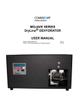
MT050A SERIES
DEHYDRATOR
USER MANUAL
Bulletin AE01B-A0527-001
© 2008 CommScope, Inc. All rights reserved.
Rev: A
(8/08)
MT050A SERIES DEHYDRATOR USER MANUAL
Table of Contents
Section 1
General Information . . . . . . . . . . . . . . . . . . . . . . . . . . . . . . . . . . . . . . . . . . . . 4
1.1
Introduction . . . . . . . . . . . . . . . . . . . . . . . . . . . . . . . . . . . . . . . . . . . . . 4
1.2
Description . . . . . . . . . . . . . . . . . . . . . . . . . . . . . . . . . . . . . . . . . . . . . 4
1.3
Operation . . . . . . . . . . . . . . . . . . . . . . . . . . . . . . . . . . . . . . . . . . . . . . 4
1.4
Alarms . . . . . . . . . . . . . . . . . . . . . . . . . . . . . . . . . . . . . . . . . . . . . . . 5
1.4.1 Multiple Alarm Option . . . . . . . . . . . . . . . . . . . . . . . . . . . . . . . . . . . . . . . 5
1.5
Figure 1 Alarm Terminal Strip(s) . . . . . . . . . . . . . . . . . . . . . . . . . . . . . . . . . . . . . . . . .5
Alarm Definitions . . . . . . . . . . . . . . . . . . . . . . . . . . . . . . . . . . . . . . . . . . 5
Changing Alarm Outputs . . . . . . . . . . . . . . . . . . . . . . . . . . . . . . . . . . . . . 5
Figure 2 Alarm Board . . . . . . . . . . . . . . . . . . . . . . . . . . . . . . . . . . . . . . . . . . . . . . . .6
Specifications MT050A Dehydrator . . . . . . . . . . . . . . . . . . . . . . . . . . . . . . . . 6
Section 2
Installation . . . . . . . . . . . . . . . . . . . . . . . . . . . . . . . . . . . . . . . . . . . . . . . . . . 7
2.1
Unpacking and Inspection . . . . . . . . . . . . . . . . . . . . . . . . . . . . . . . . . . . . 7
2.2
Controls and Displays . . . . . . . . . . . . . . . . . . . . . . . . . . . . . . . . . . . . . . . 7
2.3
Installing the Dehydrator . . . . . . . . . . . . . . . . . . . . . . . . . . . . . . . . . . . . . 8
2.3.1 19” Rack Mounting or set on shelf . . . . . . . . . . . . . . . . . . . . . . . . . . . . . . . . 8
2.4
Power Connections . . . . . . . . . . . . . . . . . . . . . . . . . . . . . . . . . . . . . . . . 8
2.4.1 AC Power . . . . . . . . . . . . . . . . . . . . . . . . . . . . . . . . . . . . . . . . . . . . . 8
Test the Dehydrator . . . . . . . . . . . . . . . . . . . . . . . . . . . . . . . . . . . . . . . . 8
2.5
Connecting the Alarm Outputs . . . . . . . . . . . . . . . . . . . . . . . . . . . . . . . . . . 8
2.6
Connecting Dehydrator to the Transmission Line . . . . . . . . . . . . . . . . . . . . . . . . 8
2.7
Purging the Transmission Line . . . . . . . . . . . . . . . . . . . . . . . . . . . . . . . . . . 9
Section 3
Maintenance . . . . . . . . . . . . . . . . . . . . . . . . . . . . . . . . . . . . . . . . . . . . . . . . 10
3.0
Maintenance . . . . . . . . . . . . . . . . . . . . . . . . . . . . . . . . . . . . . . . . . . . 10
3.1
Preventive Maintenance . . . . . . . . . . . . . . . . . . . . . . . . . . . . . . . . . . . . . 10
3.2
Dehydrator Filter Element Replacement . . . . . . . . . . . . . . . . . . . . . . . . . . . . 10
3.3
Annual Inspection . . . . . . . . . . . . . . . . . . . . . . . . . . . . . . . . . . . . . . . . 10
Check the electrical connections. . . . . . . . . . . . . . . . . . . . . . . . . . . . . . . . . 11
Check the ground wire. . . . . . . . . . . . . . . . . . . . . . . . . . . . . . . . . . . . . . . 11
Check the hour meter . . . . . . . . . . . . . . . . . . . . . . . . . . . . . . . . . . . . . . . 11
3.4
Parts Replacement and Dehydrator Overhaul . . . . . . . . . . . . . . . . . . . . . . . . . . 11
Tools . . . . . . . . . . . . . . . . . . . . . . . . . . . . . . . . . . . . . . . . . . . . . . . . 11
Overhaul Procedure . . . . . . . . . . . . . . . . . . . . . . . . . . . . . . . . . . . . . . . 12
Unit Shutdown and Removal . . . . . . . . . . . . . . . . . . . . . . . . . . . . . . . . . . 12
3.5
Service Restoration . . . . . . . . . . . . . . . . . . . . . . . . . . . . . . . . . . . . . . . 12
MT050A SERIES DEHYDRATOR USER MANUAL
Table of Contents continued
Section 4
Troubleshooting . . . . . . . . . . . . . . . . . . . . . . . . . . . . . . . . . . . . . . . . . . . . .
Section 5
Replacement Parts . . . . . . . . . . . . . . . . . . . . . . . . . . . . . . . . . . . . . . . . . . . 17
Section 6
Customer Service . . . . . . . . . . . . . . . . . . . . . . . . . . . . . . . . . . . . . . . . . . . . 17
6.0
Introduction . . . . . . . . . . . . . . . . . . . . . . . . . . . . . . . . . . . . . . . . . . . . 17
6.1
In Case of Trouble . . . . . . . . . . . . . . . . . . . . . . . . . . . . . . . . . . . . . . . . 17
6.2
Initial Steps by Andrew . . . . . . . . . . . . . . . . . . . . . . . . . . . . . . . . . . . . . 18
6.3
Return Goods Instructions . . . . . . . . . . . . . . . . . . . . . . . . . . . . . . . . . . . . 18
6.4
Repair Center Process . . . . . . . . . . . . . . . . . . . . . . . . . . . . . . . . . . . . . 18
6.5
Loaner Units . . . . . . . . . . . . . . . . . . . . . . . . . . . . . . . . . . . . . . . . . . . 18
13
SCHEMATIC WITH ALL OPTIONS (-81315) . . . . . . . . . . . . . . . . . . . . . . . . . . . . . . . 15
Low Pressure Alarm Harness (-81015) . . . . . . . . . . . . . . . . . . . . . . . . . . . . . . . . . . . 16
Warranty . . . . . . . . . . . . . . . . . . . . . . . . . . . . . . . . . . . . . . . . . . . . . . . . . . . . . . . 19
MT050A SERIES DEHYDRATOR USER MANUAL
1.3
General Information
Section 1
1.1
MT050A Theory of operation.
Introduction
The MT050A series of DryLine® dehydrators,
while similar in moisture removal technology,
operates differently than some of the DryLine®
series of dehydrators. In order to provide a
constant supply of dry air to small air volume
systems, and to maintain an acceptable dryness
level in the product air stream, a high-pressure
reservoir tank is utilized. This reservoir tank is
connected to a pressure regulator and orifice to
yield a regulated output pressure of 5.0 psi and
a nominal flow rate of 0.2 SCFM. In addition
to supplying the output air, the reservoir tank
also provides the dry air for the feedback loop.
The feedback loop is necessary to maintain the
dryness of the membrane cartridge.
This manual contains the information you need
to install, operate and maintain your MT050A
Series DryLine® dehydrator. Please take the
time to read this manual before attempting to
operate or service the unit.
1.2
Operation
During normal operation, the bleed air in the
feedback loop will cause the pressure to slowly
drop in the internal reservoir tank, and the
MT050A compressor will cycle automatically.
These cycles will take place regardless of the
system volume or condition of the transmission
line the dehydrator is connected to. The rate of
these cycles, however, will vary.
Description
MT050A Series dehydrators provide dry air for
pressurizing small (up to 60 cubic feet, or 1700
liters, in volume) antenna and transmission line
systems. The dehydrators produce -50ºF (-45ºC)
dewpoint dry air at nominal rate of 0.2 standard
cubic feet (1.4 liters) per minute (SCFM).
When connected to a very tight system, or
the output is capped, the dehydrator will
cycle approximately every 60 minutes and
maintain 5.0 psi system pressure. When
open to atmosphere, the dehydrator will cycle
approximately every 3 minutes while providing
close to 0.2 SCFM of dry air. A typlical system
will have a cycle time somewhere in between,
depending on the severity of the leaks.
Each dehydrator consists of an electricallydriven air compressor, a membrane dryer
assembly, an automatic transmission line
pressure sensing system, and alarm outputs
housed in a rigid metal chassis. It is designed to
mount directly to the rack or as a free-standing
unit. The front panel features a control interface
with display for alarms and pressure. For
easy serviceability, power connections, alarm
output connections, and all filter elements are
accessible from the outside or through easy to
access service panels.
The MT050A maintains transmission line
pressures at 5.0 lb/in2 (34 kPa). It is intended
for standard microwave antenna applications
and any other transmission line pressurization
requirement that supports a medium pressure
limit.
The display will also reflect a pressure between
0 and 5.0 psi while the output flow is between 0
and 0.2 SCFM. The pressure sensor measures
pressure beyond the flow control orifice and will
show the actual pressure in the transmission
lines (or to the distribution manifold).
During the initial pressurization of the
transmission line, the dehydrator will cycle every
2 to 4 minutes with the system at 0 psi pressure.
As the dehydrator pressurizes the system, the
cycle times will increase and the pressure will
rise until the dehydrator output is balanced with
the system leak, at which point the cycle times
will stabilize.
MT050A SERIES DEHYDRATOR USER MANUAL
1.4
1.4.1
Alarms
Alarm Definitions:
The MT050A offers Low Pressure and Excess
Run alarms as a standard feature. Alarm
conditions are indicated on the display. Alarms
are output as a common summary alarm, with
a form C dry contact. The alarm is set for
continuity on alarm.
Power Fail:
Activates open when power is
removed from the dehydrator. This
includes turning the power off at the
switch.
High Humidity:
Activates when system or
dehydrator output humidity rise
above 7.5% relative humidity. At
initial installation, this alarm will
continue to alarm until the system
has been properly purged.
Excess Run:
Factory strapped run time set in
accordance with the normal run
time for the dehydrator application.
Selectable times are 10, 30, 120
and 240 minutes, with the 10 minute
selection used on the MT050A.
Low Pressure:
If system pressure falls below the
low-pressure trigger point, the lowpressure alarm sensor will activate
an alarm contact. This alarm is an
indication of a significant system
leak or a dehydrator failure.
Multiple Alarm Option
This optional assembly is designed to provide
the additional High Humidity alarm to Andrew
Dehydrators. All alarms are Form C dry contacts
and are factory set for continuity at alarm (mains
power fail alarm opens at alarm).
This optional assembly will also indicate discrete
alarms on the display, and provide individual
contacts and connections for discrete alarms.
The external alarm monitoring system (supplied
by others) is connected to the terminal strip
located on the rear of the cabinet. A small
slotted screwdriver is necessary to make the
connections.
The connection to the alarm strip is as follows,
refer to Figure 1 for correct locations and colors
of the wires on the terminal strip.
Changing Alarm Outputs:
Alarm
Factory setting
Where To Reset Summary
Alarm
Normally Open (N.O.)
TB3 on Control
Board
Multiple Alarms
Figure 1
Term.
1
2
3
4
5
6
7
8
Function
Power Fail Com
Power Fail Alarm
Humidity Com
Humidity Alarm
Excess Run Com
Excess Run Alarm
Low Press. Com.
Low Press. Alarm
Wire Color
Black
Red
Green
Brown
Blue
White
Gray
Orange
Alarm
Factory setting
Where To Reset
Low Pressure
Mains (Power)
Normally Open (N.O.)
A-B
Normally
Closed (N.C.)
B-C
Low Pressure jumper JP4 on
alarm PCB
Excess
Run
Normally
Open (N.O.)
A-B
Jumper JP1 on
Run Alarm
PCB
High Humidity
Normally
Open (N.O.)
A-B
Jumper JP2 on
Alarm PCB
Power Fail
Jumper JP3 on
Alarm PCB
MT050A SERIES DEHYDRATOR USER MANUAL
J2
Press. Switch
PS2
J4
Humidity Sensor
J5
Main Power
JP2
Power Selector
Input
AC - (A-B)
DC - (B-C)
JP1
Compressor
Excess Alarm
Timer (10 min.)
J3
Timer Connection
JP3
Compressor
Voltage Timer
Set (120v)
JP4
Aux (A-B) N.O.
J1
Press. Switch
PS1
FUSE
5 amp, 250V
Figure 2
1.5
Specifications MT050A Dehydrator
Output Pressure
Constant
5.0 PSI (35kPa)
Output capacity
12.0 SCFH (340liters/h)
(total, approx.) 0.12 SCFM
(3.4 liters/m)
Output Dew Point,
-50°F (-45°C) or better
Operating Temperature
Range
33° to +104° F
(1° to +40° C)
Low Pressure Alarm
1.0 lb/in2 (6.9 kPa)
Electrical Input 115/230 Vac, 50/60 Hz (auto
switching)
Output Connector
3/8” polytube, compression
Dimensions
17” W x 7” H x 17” D
432mm H x 178mm W x
432mm D
Weight
36 1/2 lbs 16.55 kg
Optional Alarms
High Humidity Alarm
Set Point 7.5% RH, factory set
Excess Run Alarm
Set Point
10 minutes, factory set
Power Fail Alarm
loss of input power
MT050A SERIES DEHYDRATOR USER MANUAL
Installation
Section 2
2.1
Unpacking and Inspection
Open carton.
Mode 1:
Displays pressure and total run hours.
Mode 2:
Displays pressure and total run hours,
flashes current condition.
Mode 3:
Displays last ON and last OFF times.
Remove the top piece of closed-cell foam packaging. Carefully remove the installation accessories and
manual and dehydrator. Check the dehydrator for
shipping damage such as dents or loose parts.
2.2
Controls and Displays
Familiarize yourself with the controls and
displays prior to installing or testing the
dehydrator.
ON/OFF
Switch
MODE
Switch
ON/OFF SwitchToggles unit condition ON and OFF.
Mode Switch
Toggles between display modes.
MT050A SERIES DEHYDRATOR USER MANUAL
2.3
Installing the Dehydrator
2.3.1
19” Rack Mounting or set on shelf
2.4
Power Connections
Test the Dehydrator
Turn the dehydrator ON and check the output
port on the rear of the unit to make sure air is
flowing.
Confirm your dehydrator electrical input matches
the available power.
2.5
To connect the alarms, locate the terminal block
(TB-1) on the rear of the unit.
115 Vac/230 Vac, 50/60 Hz
(auto switching)
MT050A-81015
MT050A-81315
24/48 Vdc options are available with appropriate
inverter kit
2.4.1
Connecting the Alarm Outputs
AC Power
AC units can be connected into a standard 15
Amp power receptacle of the proper voltage.
Make sure the power circuit is properly
grounded.
Two power cords are supplied, one 115 Vac
American and one 230 Vac International.
Place alarm connection wires in proper terminals
and tighten the screw on the terminal block.
The relay contacts are rated at 2 A (noninductive), 30 Vdc.
Optional alarms (if purchased) will also be
located on this terminal (see section 1.4 for
terminal numbers).
CAUTION:
Proper electrical connection is required.
It is suggested a licensed electrician be
contracted to connect the AC wiring to the
unit, if it is connected directly to the mains.
Failure to properly connect the power wires
could result in a dangerous electrical shock
hazard.
2.6
Connecting Dehydrator to the Transmission Line
CAUTION:
Check the antenna and transmission line
system pressure rating before connecting
the dehydrator to the system.
Insert one end of the 3/8” polytube feed line
tubing into the compression fitting on the
dehydrator output port. Tighten securely with
a 9/16” wrench. Be careful not to over tighten. Connect the other end of the polytube to the
transmission line.
MT050A SERIES DEHYDRATOR USER MANUAL
Note:
If the transmission lines have not been purged,
continue with section 2.7. Otherwise proceed to
section 3.
2.7
Purging the Transmission Line
Air in the transmission line system must be
replaced with dry air to ensure satisfactory
operation of the transmitted signal.
1.
Determine the total system volume.
2.
Divide the system volume by the flow
rate of the dehydrator (12 CFH) to
determine the number of hours needed
for the purge cycle.
3.
Open the far end of the transmission line.
4.
Operate the dehydrator for three purge
cycles.
If it is not possible to open the far end of the
transmission line, follow these steps:
1.
Connect the dehydrator to the
transmission line and pressurize the
system. The system pressure should
reach 5.0 PSI.
2.
Wait 15 minutes while the air absorbs
moisture in the system, then disconnect
the dehydrator from the transmission
line and allow the air to vent.
3.
Repeat steps 1 and 2 twelve times to
purge the system.
MT050A SERIES DEHYDRATOR USER MANUAL
CAUTION:
Do not apply oil or other chemicals to the
filter element.
Maintenance
Section 3
3.0
Maintenance
Make sure the element is seated completely in
the housing and then replace the cover. Discard
the old element.
The MT050A Dehydrator requires relatively
little maintenance to ensure satisfactory
operation over long periods of time. This section
outlines the recommended annual preventive
maintenance for the unit and the suggested
overhaul for every 6000 hours of compressor
operation.
3.1
3.3
Warning:
Electrical Hazard! Unplug power cord before
servicing unit.
Preventive Maintenance
Inspection includes checking for loose
or damaged hoses, fittings and electrical
connections. Open the top cover and front door
and verify that there is no water build-up in the
two filter bowls located inside the front cover of
the dehydrator. There may be some droplets
of water in the filter bowels (the lower portion
of each bowl), but there should be only a small
amount of liquid in either bowl.
The annual maintenance of a MT050A consists
of a preventative maintenance inspection of the
dehydrator and cleaning (or replacement) of the
foam air intake filter.
These tasks can easily be performed in the field
with the unit connected to the transmission line
system and with only the front and side access
doors opened for maintenance.
In addition to the annual inspection, a complete
overhaul is recommended every 6000 hours or
sooner if local conditions warrant.
3.2
Annual Inspection
Dehydrator Filter Element Replacement
Clean/replace the air intake filter
The air intake filter protects the compressor from
contamination and dust. Periodic replacement
extends the life of the compressor.
To gain access to the element, push in on the
cover and rotate the house approximately 1/4
turn CCW..
The filter is made of a fibrous material. It should
be replaced once a year (or more frequently, if
the operating environment is very dusty.)
10
MT050A SERIES DEHYDRATOR USER MANUAL
Check the hour meter
Check the hour meter on the front panel to
determine the duty cycle of the dehydrator.
If the dehydrator has been running for more
than 20% of its installed time, check the systems
for leaks. Also check the time on the meter to
determine if it is time to perform the 6000-hour
overhaul.
3.4
Parts Replacement and Dehydrator Overhaul
Andrew MT050A Dehydrators are designed
to give many years of trouble-free service
and require very minimal maintenance. The
dehydrator contains, as a standard feature, an
hour meter that records compressor run hours. To ensure continuous and reliable operation,
the dehydrator must be overhauled every 6000
hours of compressor operation. The kits, shown
in Section 5, contain all of the necessary parts to
perform this overhaul. The dehydrator overhaul
kit includes parts to overhaul the compressor
and critical components in the dehydrator that
often become worn over time.
If there is excessive water, refer to the
troubleshooting section. Replacement of the
filter elements in the water filter and coalescing
filter is covered in the overhaul section of this
manual.
Check the electrical connections.
Check the screw at the power input connector
to ensure that the AC power cord is securely
terminated. Check the screw-in alarm terminals
to ensure that all wire connections are tight.
IN CASE OF DIFFICULTY: If the dehydrator is
not operating, refer to Section 2 on Installation
and Section 4 on Troubleshooting the unit.
A loose or damaged connection may result in
erratic operation and unnecessary downtime.
Refer to the troubleshooting section if an
electrical problem is encountered.
Tools
Check the ground wire.
The following tools are used in the maintenance
and overhaul procedures.
Check that an electrical safety ground is
installed on the stud on the rear of the
dehydrator. This connection point is to adjacent
the power input connector. (It is intended to be
customer installed in the field.)
11
Adjustable open-end wrench
Allen wrench 5/32
#2 Phillips screwdriver
Small flat-blade screw-driver
MT050A SERIES DEHYDRATOR USER MANUAL
Overhaul Procedure
When the MT050A compressor run time reaches
6000 hours (or a multiple of 6000 hours) it is
time to replace certain items in the compressor
and the air path of the dehydrator. These
include the piston cups, piston seals and head
gaskets of the compressor, the filter elements
in the water and coalescing filters, and the tube
section connecting the compressor output to the
water filter input.
Unit Shutdown and Removal
Follow the instructions included in the
compressor overhaul kit. When the overhaul is
complete, reinstall.
In order to perform an overhaul on the MT050A,
the unit must be turned off and removed from
service. As this is being done, the low pressure
alarm may activate through a reporting alarm
system. Personnel monitoring such an alarm
should be notified in advance so that they are
aware of the fact that service is being performed. It is also necessary to disconnect the dehydrator
dry air output from the waveguide system during
the overhaul.
3.5
RECOMMENDATION:
If the dehydrator overhaul process has taken
more than a few hours, it is recommended that
the unit be run for one hour into the room, to
purge the membrane dryer and tank of any
acquired moisture, before reconnecting to the
transmission line system.
Remove the chassis top and side panels for
overhaul.
1.
Unplug the unit from the power supply.
2
Follow the instructions included in
the compressor overhaul kit. When
the overhaul is complete, reinstall. Complete overhaul can be done without
removing the compressor from the
chassis. The compressor head, air filter,
output port and relief valve can all be
removed though side panel.
Service Restoration
12
MT050A SERIES DEHYDRATOR USER MANUAL
Troubleshooting
Section 4
If you experience difficulty with your dehydrator, use the troubleshooting procedures described below.
Caution:Electrical troubleshooting requires access to potentially dangerous voltages and should
only be performed by a licensed electrician.
Problem/Condition
Solution
If the display light fails to light, make sure the unit is
plugged in and power outlet is operating.
Dehydrator display does not light, unit does not run.
If you still have no light, unplug the unit, remove the unit
cover and check for loose connections. Refer to the wiring
diagram for proper connections.
Check to assure that the fuse is OK.
Check to assure that proper AC voltage is being supplied
to the input.
Plug the unit output with finger and observe pressure
gauge. The pressure gauge line should read
approximately 5.0 psi and the alarm should clear. If alarm
does not clear, remove cover and verify tubing and wiring
connections are secure.
Low-pressure alarm activated.
If the pressure does not remain constant after plugging
the output, apply leak detector to isolate the leak in the
dehydrator (exercise care when applying solution not to
wet wiring or electronics).
With dehydrator isolated from transmission line, observe
pressure in transmission line. If pressure drops, use a leak
detector solution to locate leaks in the transmission line. Repair leaks if possible.
If the problem persists contact Andrew Customer Service.
Compressor does not turn OFF.
Check the display on the controller. Toggle the ON/OFF
switch (left of the display).
Check input power polarity and voltage per wiring diagram.
Filter bowls show excessive water.
Ensure that the drain line tubing (exiting the bottom of the
unit) is not clogged. When the compressor cycles off, air
and moisture should flow out of the drain line (into drain
pan).
13
MT050A SERIES DEHYDRATOR USER MANUAL
NOTES:
14
15
ORANGE
GRAY
WHITE
BLUE
BROWN
GREEN
RED
BLACK
GREEN
EMPTYSLOT
J3
TB4
TB3
J1
J4
RED
BLACK
TB1
WHITE
BLACK
BLACK
WHITE
GREEN/
YELLOW
GROUND
BLACK
WHITE
WHITE
GREEN/YELLOW
SCHEMATIC WITH ALL OPTIONS (-81315)
J2
TB2
BLACK
GREEN/YELLOW
WHITE
BLACK
SV1
MT050A SERIES DEHYDRATOR USER MANUAL
Low Pressure Alarm Harness (-81015)
MT050A SERIES DEHYDRATOR USER MANUAL
16
MT050A SERIES DEHYDRATOR USER MANUAL
Replacement Parts
Section 5
Customer Service
Section 6
The following is a list of the replacement kits for the
MT050A Series dehydrators:
Check website for latest updates to manual and
parts list.
6.0
Introduction
Andrew provides in-warranty and out-of-warranty
repairs as well as dehydrator and compressor
overhauls from several Repair Centers. Coordination of these services is provided
through the nearest Sales Office or Customer
Service Center. The Center is also prepared to
help you with the following:
Overhaul Kit
MT050A-KIT-OVRHL
6.1
Technical Assistance
Troubleshooting
Repairs
Loaner Units
Spare Parts
Installation Materials
System Accessories.
In Case of Trouble
The first step you should take if trouble
develops using a dehydrator is to read the
operators manual and follow the trouble isolating
procedures given in it.
Filter Element Replacement Kit
MT050A-KIT-ELMNT
If the steps in the manual do not identify and
remedy the problem, then contact an Andrew
Customer Service Center for 24-hour telephone
assistance. Record the Model Number (e.g.
MT050A) and Serial Number from the product
label, as you will be asked for these when you
call. Two main locations are currently available
to help:
Filter Bowl Assemble Replacement Kit
MT050A-KIT-FLTRS
in North America
Telephone: 1-800-255-1479
Fax (U.S.A.): 1-800-349-5444
in Europe
Telephone: +44 1592 782612
Fax Number: +44 1592 782380
Filter Bowl Assemble and Dryer Tube Replacement Kit
MT050A-KIT-DRYER
International
Telephone: +1-779-435-6500
Fax Number: +1-779-435-8579
Web Access
Internet: www.commscope.com
Email: #[email protected]
Solenoid Replacement
Kit MT050A-KIT-SOLND
17
MT050A SERIES DEHYDRATOR USER MANUAL
6.2
Initial Steps by Andrew
If you have saved the original packaging
that came with the unit, use it to return the
dehydrator for repair. If a loaner unit (of the
same type) was supplied by Andrew, use the
loaner unit box to return the original dehydrator.
When your call or fax communication is
received, the Andrew staff will work with you to
pinpoint the possible cause of trouble. If the
pressurization equipment is suspect, they will:
6.3
*
ask for your unit Model Number and
Serial Number
*
check the warranty status of the unit
*
advise the availability of a loaner unit
*
provide of the cost for inspection and
repairs, if the unit is out-of-warranty
*
fax a Return Goods Authorization Sheet
to you.
6.4
The Andrew Dehydrator Repair Center will
receive your unit and inspect it for any transport
damage. The unit will then be analyzed for
troubles using the description you have supplied
and the specialized experience the Repair
Center staff have with dehydrators.
If the unit is in-warranty, repairs are made at no
charge and the unit will be returned to you by
the same mode of transport as it was received.
If the unit is in-warranty, but no problems are
found, the unit will be thoroughly tested before
being returned to you. A nominal inspection fee
will be charged for this service.
Return Goods Instructions
After you have contacted Andrew and received a
Return Goods Authorization Number (RGN), you
will need to take the following steps to send the
faulty unit to a Repair Center:
*
If your unit is out-of-warranty, it will be inspected
and repaired for the quoted fee.
6.5
make a copy of the Return Goods
Authorization Sheet that was faxed to
you
*
write a brief description of the trouble
you are encountering and attach this to
the copy of the sheet
*
pack the unit (with at least 4-inches of
protective packaging on all sides)
*
enclose the authorization sheet and
trouble description within the box
*
enclose a purchase order or other
method of payment for non warranty
repairs.
*
mark the outside of the box with the
RGN
*
return the box to the Repair Center
address listed on the authorization
sheet.
Repair Center Process
Loaner Units
The Andrew dehydrator Repair Centers stock
a limited number of “loaner” dehydrator units of
both current and discontinued products. These
units, while not new, are still in excellent working
order.
Loaners are available on a first-come firstserved basis. They are issued in conjunction
with the original RGN and are invoiced at a
nominal price. You will need to request a
second RGN to return the loaner unit. A credit
memo is issued by the Repair Center when a
loaner is returned
18
MT050A SERIES DEHYDRATOR USER MANUAL
19
MT050A SERIES DEHYDRATOR USER MANUAL
This page was left blank.
20