1
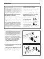
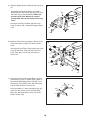
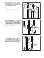
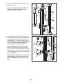
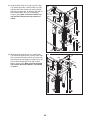
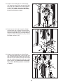
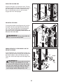
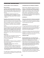
37. Wrap the Arm Cable (145) over a “V”-pulley (75).
Attach the “V”-pulley, a Large Cable Trap (77),
and two Full Pulley Guards (76) to the other side
of the bracket on the Center Upright (13) with an
M10 x 60mm Bolt (133) and an M10 Nylon
Locknut (153). Make sure that the Cable Trap is
oriented to hold the Cable in the groove of the
“V”-pulley.
37
133
76
75
77
145
76
153
13
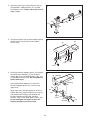
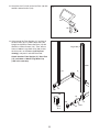
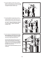
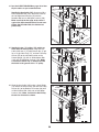
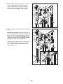
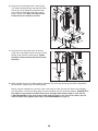
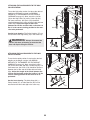
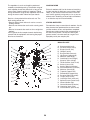
38. Grease an M8 x 22mm Shoulder Bolt (143).
Attach the Arm Cable (145) to the Right
Adjustment Bracket (24) with the Shoulder Bolt
and an M8 Nylon Locknut (170). See the inset
drawing. Make sure that the flat edge of the
cable is against the Adjustment Bracket. Do
not overtighten the Shoulder Bolt; the Cable
must pivot easily.
38
Grease
143
145
24
170
143
145
24
170
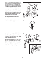
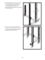
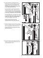
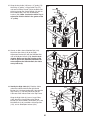
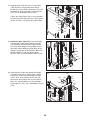
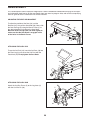
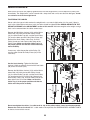
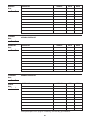
39. Identify the High Cable (81). Feed the Cable
under the indicated rod into the right Swivel
Bracket (31). Continue feeding the Cable into the
Top Frame (17), and then pull the end of the
Cable out of the indicated slot in the Top Frame.
39
Slot
127
17
148
31
151
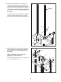
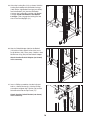
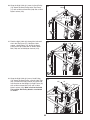
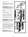
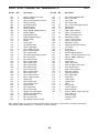
Wrap the High Cable (81) over a Large Pulley
(165). Attach the Large Pulley to the Swivel
Bracket (31) with an M10 x 55mm Bolt (127), two
M10 Washers (148), two M10 x 6.5mm Spacers
(151), and an M10 Nylon Locknut (153).
Rod
165
81
Ball
21
153
151 148