1
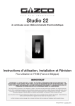
Riva 53/67
Inset Convector Fire - Balanced Flue
With Upgradeable Control Valve
Instructions for Use, Installation & Servicing
For use in GB & IE (Great Britain & Republic of Ireland).
IMPORTANT
THE OUTER CASING, FRONT AND GLASS PANEL BECOME EXTREMELY HOT DURING OPERATION AND
WILL RESULT IN SERIOUS INJURY AND BURNS IF TOUCHED. IT IS THEREFORE RECOMMENDED THAT A
FIREGUARD COMPLYING WITH BS 8423:2002 IS USED IN THE PRESENCE OF YOUNG CHILDREN, THE
ELDERLY OR INFIRM.
This product contains a heat resistant glass panel. This panel should be checked during Installation and at each servicing interval. If any
damage is observed on the front face of the glass panel (scratches, scores, cracks or other surface defects), the glass panel must be
replaced and the appliance must not be used until a replacement is installed. Under no circumstances should the appliance be used if any
damage is observed, the glass panel is removed or broken.
It is essential that ALL of the screws that retain the glass frame are replaced and tightened correctly. Under no circumstances should the
appliance be operated if any of these screws are loose or missing.
These Instructions must be left with the appliance for future reference and for consultation when servicing the appliance. Please make the
customer aware of the correct operation of the appliance before leaving these instructions with them.
The commissioning sheet found on Page 3 of this Instruction manual must be completed by the Installer prior to leaving the premises.
PR0639 Issue 12 (February 2014)
Contents
Riva 53/67 - Balanced Flue
Covering the following models:
Gas Type
Nat. Gas
LPG
RIVA 53
RIVA 67
8592
8595LUC
P8592
P8595LUC
Appliance Commissioning Checklist.......................3
User Instructions........................................................4
Installation Instructions...........................................10
Technical Specifications ........................................................... 10
Site Requirements..................................................................... 12
Installation................................................................................. 18
Commissioning.......................................................................... 25
Servicing Instructions..............................................26
Fault Finding.............................................................................. 26
How to Replace Parts............................................................... 28
Basic Spare Parts List............................................................... 33
Service Records........................................................................ 34
2
To receive your Extended Warranty your Gazco appliance must have
been purchased from our Expert Retailer Network and registered within
one month of purchase or installation. Please note that all warranties
are effective from the date of purchase. Any Gazco product purchased
outside of our Extended Retailer Network, or not registered within the
stated time will carry a standard 12 month warranty.
It is a condition of the Extended Warranty that the installation
complies with the relevant Building Regulations and is carried out
by a suitably trained and qualified individual (GasSafe in the UK or
equivalent in other countries) with the certificate of installation and the
Commissioning Report on Page 3 completed and retained by the end
user.
Full terms and conditions are detailed in the Warranty Statement on
the Gazco website www.gazco.com. In the event of any conflict of
information the wording on the website shall prevail.
Important Note: Should any problems be experienced with your
product, claims must first be submitted to the Expert Retailer where
the appliance was purchased from who will offer immediate assistance
or contact Gazco on your behalf.
Appliance Commissioning Checklist
To assist us in any guarantee claim please complete the following information:-
IMPORTANT NOTICE
Explain the operation of the appliance to the end user, hand the completed instructions to them for safe keeping,
as the information will be required when making any guaranteed claims.
FLUE CHECK
PASS
FAIL
1. Flue Is correct for appliance
2. Flue flow Test
3. Spillage Test
GAS CHECK
1. Gas soundness & let by test
2. Standing gas pressure
mb
3. Appliance working pressure (on High Setting
mb
4. Gas rate
m3/h
NB All other gas appliances must be operating on full
5. Does Ventilation meet appliance requirements N/A
SAFETY CHECK
1. Glass checked to ensure no damage, scratches, scores or cracks.
2. Glass frame secured correctly and all screws replaced
RETAILER AND INSTALLER INFORMATION
Retailer. . . . . . . . . . . . . . . . . . . . . . . . . . . . . . . . . . . . . . . . . . . . . . . Installation Company. . . . . . . . . . . . . . . . . . . . . . . . . . . . . . . . . . . . . . . . . . . . . . . . . . . . . . . . . . . . . . . . . . . . . . . . . . . . . . . . . . . . . . . . . . . . . . . . . . . . . . . . . . . . . . . . . . . . . . . . . . . . . . . . . . . . . . . . . . . . . . . . . . . . . . . . . . . . . . . . . . . . . . . . . . . . . . . . . . . . . . . . . . . . . . . . . . . . . . . . . . . . . . . . . . . . . . . . . . . . . . . . . . . . . . . . . . . . . . . . . . . . . . . . . . Contact No.. . . . . . . . . . . . . . . . . . . . . . . . . . . . . . . . . . . . . . . . . . . Engineer. . . . . . . . . . . . . . . . . . . . . . . . . . . . . . . . . . . . . . . . . . . . .
Date of Purchase. . . . . . . . . . . . . . . . . . . . . . . . . . . . . . . . . . . . . Contact No.. . . . . . . . . . . . . . . . . . . . . . . . . . . . . . . . . . . . . . . . . . Model No. . . . . . . . . . . . . . . . . . . . . . . . . . . . . . . . . . . . . . . . . . . . . Gas Safe Reg No. . . . . . . . . . . . . . . . . . . . . . . . . . . . . . . . . . . . Serial No.. . . . . . . . . . . . . . . . . . . . . . . . . . . . . . . . . . . . . . . . . . . . . Date of Installation. . . . . . . . . . . . . . . . . . . . . . . . . . . . . . . . . . Gas Type. . . . . . . . . . . . . . . . . . . . . . . . . . . . . . . . . . . . . . . . . . . . . 3
User Instructions
Welcome
Congratulations on purchasing your Riva fire, if installed
correctly Gazco hope it will give you many years of warmth
and pleasure for which it was designed.
The purpose of this manual is to familiarise you with your
appliance, and give guidelines for its installation, operation and
maintenance. If, after reading, you need further information,
please do not hesitate to contact your Gazco retailer.
WARNING
In the event of a gas escape or if you can smell
gas, please take the following steps:
• Immediately turn off the gas supply at the
meter/emergency control valve
• Extinguish all sources of ignition
• Do not smoke
• Do not operate any electrical light or power
switches (On or Off)
• Ventilate the building(s) by opening doors
and windows
• Ensure access to the premises can be made
Please report the incident immediately to the
National Gas Emergency Service Call Centre
on 0800 111 999 (England, Scotland and Wales)
, 0800 002 001 (N. Ireland) or in the case of
LPG, the gas supplier whose details can be
found on the bulk storage vessel or cylinder.
The gas supply must not be used until
remedial action has been taken to correct the
defect and the installation has been
recommissioned by a competent person.
1. General
1.1
Installation and servicing must only be carried out by a
competent person whose name appears on the Gas Safe
register. To ensure the engineer is registered with Gas Safe
they should possess an ID Card carrying the following logo:
1.3
Do not place curtains above the appliance:
You must have 300mm (1’) clearance between the appliance
and any curtains at either side.
1.4
No furnishings or other objects should be placed within
1 metre of the front of the appliance.
1.5
If a shelf is fitted, a distance of 150mm above the appliance
is required.
1.6
If any cracks appear in the glass panel do not use the
appliance until the panel has been replaced.
1.7
If, for any reason, the flue has to be removed from the
appliance, the seals must be replaced in the inner spigot.
1.8
Do not obstruct the flue terminal in any way, i.e. by planting
flowers, trees, shrubs etc. in the near vicinity, or by leaning
objects against the terminal guard.
1.9
Do not put any objects on the terminal guard; it will lose its
shape.
1.10 If you use a garden sprinkler, do not let quantities of water
into the flue terminal.
1.11 In the unlikely event the appliance is receiving interference
from other electronic devices, the handset/Control box can
be reprogrammed. Please consult your retailer if you think
this may be the case.
1.12 This product is guaranteed for 5 years from the date of
installation, as set out in the terms and conditions of sale
between Gazco and your local Gazco retailer. Please
consult with your local Gazco retailer if you have any
questions. In all correspondence always quote the Model
Number and Serial Number.
2. Operating the Appliance
2.1
The control valve is at the foot on the right-hand side of the
appliance. It has two controls, Diagram 1:
1. The right-hand knob controls the pilot ignition
2. The left-hand knob controls the main burner
2.2
Refer to separate instructions if your appliance is upgraded
to include battery remote control. The instructions below
apply whether or not you have the remote upgrade.
Lighting the Pilot
2.3
1
1.2
4
In all correspondence, please quote the appliance type
and serial number, which can be found on the data badge
located on a plate attached to the lower slotted trim.
To start the left-hand and right-hand control knobs must
both point to off ( ):
User Instructions
2.4
Press in the right-hand control knob and rotate anticlockwise until a click is heard. Continue to press in. The
knob points to the pilot ( ).
The pilot is lit
Standard Remote Control
(PART NUMBER 8455)
4.3
This remote control can control the gas appliance after
the pilot has been lit. It can turn the main burner on and
regulate it from low through to high and back again.
It can turn the main burner off leaving the pilot burning.
2.5
Keep the knob depressed for 10 seconds before releasing.
The pilot remains lit.
Repeat the above steps if the pilot does not stay lit
NOTE: If the pilot goes out, the Interlock system
prevents you lighting again for a short period
2.6
If, after repeating the above steps the pilot does not light,
contact your Retailer or Installer.
4.4
2.7
Turn the right-hand knob to the left to main burner setting
(
)
MANUAL MODE
Adjusting the Flame height
2.8
You can now adjust the flame height and temperature using
the left-hand control knob.
2.9
Turn the left-hand knob anti-clockwise to increase the
flame height
Thermostatic and Timer Remote Control
(PART NUMBER 8456)
Can be used to turn the main burner on and manually
regulate it from low through to high and back again. It can
also be used to turn the main burner off leaving the pilot
burning.
AUTO MODE
Will automatically regulate the room to a pre-set
temperature.
2.10 Turn clockwise to decrease the height
IMPORTANT: YELLOW FLAMES TYPICALLY
APPEAR WHEN THE APPLIANCE HAS REACHED
NORMAL OPERATING TEMPERATURE. THIS CAN
TAKE UP TO 30 MINUTES.
WARNING: IF THE APPLIANCE FAILS TO LIGHT OR
BECOMES EXTINGUISHED IN USE, WAIT 3
MINUTES BEFORE ATTEMPTING TO RELIGHT.
3. Turning OFF the Appliance
3.1
To turn the main burner off turn the left-hand knob until it
points to off ( ).Just the pilot remains lit.
3.2
Press in and turn the right-hand knob until it points to off
( ). The pilot goes out.
This remote control can control the gas appliance after the
pilot has been lit.
TIMER MODE
Will turn the appliance on and off according to a pre-set
programme and automatically regulate the room
temperature during the two on periods.
5. Cleaning the Appliance
ENSURE THE APPLIANCE IS COLD BEFORE PROCEEDING
5.1
Remove the Profil frame from the appliance by removing the
2 concealed screws behind the lower access door, see
Diagram 2. Pull the frame forward at the bottom then lift
clear of the top fixing lugs.
2
4. Upgrading the Appliance
4.1
4.2
The appliance is fitted with a control valve that can easily be
upgraded to battery powered remote control.
There are two versions of this control which can be obtained
through your local Gazco stockist.
There is no requirement for this upgrade to be carried out by
an approved Gas engineer. However Gazco recommend
that this task is undertaken by a suitably competent person.
This upgrade can be fitted before or after installation but if
side clearances are limited then it will be easier to upgrade
the appliance before installation. Full instructions are
included with the kit.
Note: If the appliance is fitted with an alternative Gazco
Riva front, please refer to the separate instructions
supplied with the front.
5
User Instructions
5.2
Remove the glass door by unscrewing the screws, see
Diagram 3, arrow A.
6. Arrangement of Fuel Bed
3
Advice on handling and disposal
of fire ceramics
5.3
Remove the ceramic logs and granules, and place them on
a dry, clean surface.
5.4
The logs should not require cleaning. Do not use a vacuum
cleaner or brush to clean the logs, any large pieces of debris
may be removed by hand.
5.5
Ensure any debris is removed from the burner ports.
5.6
Replace the ceramics by referring to Section 6.
5.7
Use a damp cloth to clean the outer casing of the appliance.
5.8
To clean the glass surface, Gazco recommends you use a
ceramic glass product generally sold for cleaning ceramic hobs.
NEVER OPERATE THE APPLIANCE WHEN THE GLASS
FRAME IS REMOVED OR BROKEN.
5.9
Replace ALL of the securing screws ensuring that a screw is
present in all fixing slots.
UNDER NO CIRCUMSTANCES SHOULD THE
APPLIANCE BE USED IF ANY OF THE GLASS
FRAME RETAINING SCREWS ARE LOOSE OR
MISSING
5.10 Replace the decorative front by referring to the separate
instructions supplied with the front.
6
NOTE: ENSURE THAT THE LOGS ARE POSITIONED
CORRECTLY, SEE SECTION 6. ONLY USE THE CORRECT
AMOUNT OF LOGS AS SPECIFIED IN THE DIAGRAMS.
The fuel effect and side panels in this
appliance are made from Refractory Ceramic
Fibre (RCF), a material which is commonly
used for this application.
Protective clothing is not required when
handling these articles, but we recommend you
follow normal hygiene rules of not smoking,
eating or drinking in the work area and always
wash your hands before eating or drinking.
To ensure that the release of RCF fibres are
kept to a minimum, during installation and
servicing a HEPA filtered vacuum is
recommended to remove any dust
accumulated in and around the appliance
before and after working on it. When servicing
the appliance it is recommended that the
replaced items are not broken up, but are
sealed within heavy duty polythene bags and
labelled as RCF waste.
RCF waste is classed as stable, non-reactive
hazardous waste and may be disposed of at a
licensed landfill site.
Excessive exposure to these materials may
cause temporary irritation to eyes, skin and
respiratory tract; wash hands thoroughly after
handling the material.
Riva 67 Layout
THE BAG OF GRANULES CONTAINED IN THE LOG SET
IS TO SIMULATE AN ASH EFFECT. THIS IS NOT TO BE
PLACED ON THE BURNER.
6.1
Place some of the granules around the rear and sides of the
burner tray. ENSURE NO GRANULES FALL ON THE
BURNER, see Diagram 4.
4
User Instructions
6.2
Place log 1 (large black log) on the burner. Ensure the rear
of the log touches the rear of the burner, see Diagram 5.
8
5
6.6
CENTRALISE THE LOG BETWEEN THE BURNER
PORTS AT EITHER END.
ALL THE REMAINING LOGS EXCEPT FOR THE
SMALLEST ONE HAVE LOCATION HOLES ON THE
UNDERSIDE, THESE LOCATE ON THE STUDS AT THE
FRONT OF THE APPLIANCE.
6.3
Place log 5 on top of log 4 and ensure the two large
locations engage. Locate the front of the log on to the far
right-hand stud, see Diagram 9.
9
Place log 2 on the centre and locate the rear of the log on
the large flat area of log 1, see Diagram 6.
6
6.7
Place log 6 on the remaining stud and lean the log on to log
1 between logs 2 and 3. There is a notch to locate the log,
see Diagram 10.
10
6.4
Place log 3 on the far left-hand stud. The recess on the
underside of the log should locate on the top of log 1 on the
far left-hand side, see Diagram 7.
7
6.5
Place log 4 on the right-hand side of the centre log. There is
a large recess on the underside of the log, which is located
on log 1, see Diagram 8.
6.8
Place log 7 at the front of the appliance between logs 4 and
5. DO NOT PLACE THIS LOG ON THE BURNER. IT IS
ONLY TO FILL THE GAP BETWEEN LOGS 4 AND 5. The
charred effect should face the rear of the appliance.
Place the remaining granules between the logs so that they
cover the front metal ledge, see Diagram 11.
ENSURE NO GRANULES FALL ON THE BURNER.
7
User Instructions
14
11
Riva 53 Layout
6.9
6.12 Place log B on the first stud. The recess on the underside of the log should locate on the top of log C, see Diagram 15.
15
Place log A on to the burner. Ensure the rear of the log
touches the rear burner, see Diagram 12.
12
6.13 Place log E on the last stud. The recess on the underside of the log should locate on to the top of log D, see Diagram 16.
16
CENTRALISE THE LOG BETWEEN THE BURNER
PORTS AT EITHER END.
Four of the remaining logs have location holes on the underside.
These locate on the studs at the front of the appliance
6.10 Place log D on the third stud from the left and resting at the rear on log A, see Diagram 13.
13
6.14 Place log F on the rear tray and leaning forward to locate in the recess in log E, see Diagram 17.
17
6.11 Place log C on the second stud resting at the rear on log A.,
see Diagram 14.
8
User Instructions
6.15 Place log G at the front of the appliance between logs D and E.
DO NOT PLACE THIS LOG ON THE BURNER. IT IS ONLY TO FILL THE GAP BETWEEN LOGS D AND E.
The charred effect should face the rear of the appliance,
see Diagram 18.
8. Running In
8.1
During initial use of a new Gazco appliance a strong odour
will be encountered as various surface coatings become hot
for the first time. Although these odours are harmless it is
recommended that the appliance is operated on maximum
for 4 to 8 hours in order to fully burn off these coatings. After
this period the odours should then disappear.
If the odours persists, please contact your installer for advice.
8.2
During the first few hours of burning there may be
discolouration of the flames. This will also disappear after a
short period of use.
18
9. Servicing
9.1
6.16 With the granules fill the front compartment around the logs evenly. ENSURE NO GRANULES FALL ON THE BURNER, see Diagram 19.
The appliance must be serviced every 12 months by a
qualified Gas Engineer. In all correspondence always quote
the Model number and the Serial number which may be
found on the data badge.
10. Ventilation
19
10.1 Any purpose provided ventilation should be checked
periodically to ensure that it is free from obstruction.
11. Installation Details
11.1 Your installer should have completed the commissioning
sheet at the front of this book. This records the essential
installation details of the appliance. In all correspondence
always quote the Model number and Serial number.
6.17 Ensure that the fibreglass seal on the back of the glass
frame is intact then hook the location tabs over the hooks
on the top of the firebox. Replace the six screws working
from the top down. Tighten the screws evenly.
DO NOT OVER TIGHTEN.
NEVER OPERATE THE APPLIANCE WHEN THE GLASS
PANEL IS REMOVED OR BROKEN.
6.18 Replace the Profil frame by hooking the top over the
location lugs on top of the flanges, replace the two fixing
screws., see Diagram 2, Section 5 'Cleaning the Appliance'.
Note: If the appliance is fitted with an alternative Gazco Riva
front, please refer to the separate leaflet supplied with the
front.
7.1
12. Hot Surfaces
12.1 Parts of this appliance become hot during normal use.
12.2 Regard all parts of the appliance as a working surface.
12.3 Provide a suitable fire guard to protect young children and the infirm.
12.4 If frames other than the Profil are being fitted, refer to their
instructions.
20
NOTE: ENSURE THAT THE LOGS ARE POSITIONED AS
ABOVE. ONLY USE THE CORRECT AMOUNT OF LOGS
AS SPECIFIED IN THE DIAGRAMS.
7. Flame Failure Device
= Hot
Surface
This is a safety feature incorporated on this appliance which
automatically switches off the gas supply if the pilot goes out
and fails to heat the thermocouple.
IF THIS OCCURS DO NOT ATTEMPT TO RELIGHT THE
APPLIANCE FOR 3 MINUTES.
9
Installation Instructions
Technical Specification
Covering the following models:
Gas Type
RIVA 53
RIVA 67
Nat. Gas
8592
8595LUC
P8592
P8595LUC
LPG
Model
Gas
CAT.
Riva 53
I2H
Riva 53
I3+
Riva 67
I2H
Riva 67
I3+
Gas Type
Working
Pressure
Aeration
Natural (G20)
20mb
Butane (G30)
29mb
15 x 17
Propane (G31)
37mb
BLANK
Natural (G20)
20mb
Butane (G30)
29mb
14 x 16
Propane (G31)
37mb
6x6
Injector
14mm 16mm
Open
1 side
15mm x 17mm
Open
1 side
*LPG models. The appliance is factory set
to run on butane G30. If it is intended to
be used on propane G31 the aeration plate
supplied must be fitted.
To change aeration plate refer to section replacing parts 9.
Gas Rate
m3/h
530
Input kW
(Gross)
0.648
0.180
200
0.237
410
0.581
0.166
185
0.218
High
Low
6.8
3.25
GB, IE
6.3
3.25
GB, IE
6.1
3.0
GB, IE
5.8
3.0
GB, IE
Efficiency Class 2
Flue Outlet Size 100 Ø / 152mm Ø
Gas Inlet Connection Size 8mm Ø
RESTRICTOR REQUIREMENT
VERTICAL & HORIZONTAL FLUE SPECIFICATION
Vertical flue height from top of appliance
Horizontal length
Restrictor size
200 x 500mm
Up to 500mm
No Restrictor
500mm x 1000mm
Up to 1000mm
No Restrictor
1000mm x 1490mm
Up to 1000mm
70mm Ø
1500mm x 1990mm
Up to 5000mm
70mm Ø
2000mm x 3000mm
Up to 5000mm
60mm Ø
TOP EXIT-VERTICAL ONLY INCLUDING OFFSET
10
Country
Vertical flue height from top of appliance
Restrictor size
3000mm x 4990mm
52mm Ø
5000mm x 10000mm
47mm Ø
Installation Instructions
Technical Specification
This appliance has been certified for use in countries other than
those stated. To install this appliance in these countries, it is
essential to obtain the translated instructions and in some cases
the appliance will require modification. Contact Gazco for further
information.
NOTE: All dimensions refer to the Riva 53 & Riva 67 when
fitted with the Profil front.
Please refer to the separate Installation leaflet supplied with any
alternative Gazco Riva front for applicable dimensions.
PACKING CHECKLIST
Qty Description
Fixing Kit containing:
1 x Cassette and burner
assembly
1 x Decorative frame
1 x Ceramic back panel *
1 x Ceramic LH side panel *
1 x Ceramic RH side panel *
1 x Log set (7 logs)
1 x Bag of granules
1
1
4
4
1
2
x
x
x
x
x
x
Fixing kit containing:
Instruction manual
Woodscrews
Rawlplugs
Self adhesive foam strip
Frame retaining screws
* Fitted in appliance
RIVA 53 DV
24
118
705
41
24
565
660
30
339
398
82
534
RIVA 67 DV
24
659
41
24
570
339
30
525
83
524
118
692
11
Installation Instructions
Site Requirements
1. Flue & Chimney Requirements
NOTE: This appliance can only be installed in
conjunction with the flue supplied.
1.1
The flue must be sited in accordance with BS5440: Part 1
(latest edition) (see Diagram below).
1.2
Any terminal which is less than 2 metres above any access
(level ground, balcony or above a flat roof to which people
have access) is to be fitted with a guard.
1.3
All vertical and horizontal flues must be securely fixed and
fire precautions followed in accordance with local and
national codes of practice.
1
12
1.4
A restrictor may be required, see Technical Specifications on
page 15.
1.5
Two types of flue terminals are available, horizontal and
vertical. For a horizontal terminal, decide on the terminal
position and measure the height from the top of the
appliance to the centre of the required hole. For minimum
and maximum flue dimensions, see Diagram 1A/1B.
1.6
Access must be left either above or at the side of the
installation to allow the flue to be assembled on top of the
appliance. When a horizontal terminal is used, the vertical
sections are assembled first, then the 90-degree elbow and
finally the horizontal section including the terminal. If a
masonry installation is to be built, a suitable lintel must be
used to support the opening.
1.7
Only the horizontal terminal section can be reduced in size.
Installation Instructions
Site Requirements
2. Flue Options
1C
1A
Start of bend to centre line of horizontal flue 170mm.
Centre line of vertical flue to end of bend 220mm.
1B
2.1
TOP FLUE UP & OUT KIT (8534/8534AN)
Vertical from the top of the appliance then horizontally out.
see diagram 1A. The basic kit comprises:
1 x 200mm vertical length
1 x 500mm terminal length (cut to length on site)
1 x 90 degree elbow
1 x wall plate
1 x 70mm restrictor
1 x 60mm restrictor fixing screws
The kit may be used on its own. (Note – with a 200mm rise
only the 500mm terminal length can be used). Extra lengths
may be added to the vertical and horizontal, see Section 2.5.
2.2
TOP FLUE UP & OUT WITH ADDITIONAL BEND
Any additional bend may be used on the horizontal section
(either 45° or 90°), but the overall horizontal flue run will be
reduced. Refer to diagram 1B.
2.3
TOP FLUE VERTICAL KIT (8524/8524AN)
Vertical from the top of the appliance, see Diagram 1C.
A minimum vertical rise 3m (9’10") to a maximum 10m
(32’10"). The basic kit comprises:
2 x 1m lengths
1 x 1m terminal length
1 x 52mm restrictor
1 x 47mm restrictor
Extra lengths may be added, see Section 2.5.
13
Installation Instructions
Site Requirements
2.4
TOP FLUE VERTICAL OFFSET KIT (8530/8530AN)
3.5
Used with kit 8524. A minimum rise of 500mm (191/2) is
required to the first bend, see Diagram 1C.
All supply gas pipes must be purged of any debris that may
have entered, prior to connection to the appliance.
3.6
2.5
EXTRA FLUE LENGTHS
The gas supply enters through the silicone panel located on
the RH side of the outer box; this will need to be slit with a
sharp knife prior to passing the supply pipe through.
All flue components are 150mm diameter (6")
Nominal
Length
Actual
Length
Stainless
Finish
4. Ventilation
Anthracite
Finish
200mm
140mm
8527
8527AN
500mm
440mm
8528
8528AN
1000mm
940mm
8529
8529AN
40° Bend
N/A
8507
8507AN
90° Bend
N/A
8508
8508AN
4.1
This appliance requires no additional ventilation.
5. Appliance Location
5.1
This appliance must stand on a non-combustible hearth that
is at least 12mm thick; the minimum opening dimensions
are shown in Diagram 2a.
2a
NOTE: The following areas need careful consideration.
a)Terminal positions
b)Flue supports
c)Weatherproofing
d)Fire precautions
For all the above options, local and national codes of
practice must be adhered to.
3. Gas Supply
3.1
3.2
3.3
Before installation, ensure that the local distribution
conditions (identification of the type of gas and pressure)
and the adjustment of the appliance are compatible.
Ensure that the gas supply is capable of delivering the
required amount of gas and is in accordance with the rules
in force.
3.4
14
This appliance is supplied complete with a factory fitted
isolation device incorporated into the inlet connection, no
further isolation device is required.
Riva 53
Riva 67
A
540mm
668mm
B
350mm
350mm
C
665mm
530mm
5.2
NOTE: If this appliance is fitted less than 150mm from
the floor then it will require a hearth to protect the floor.
It should have minimum dimensions of 12mm thick
projecting 300mm in front and 150mm either side of the
appliance.
5.3
This appliance is not suitable for installation onto a
combustible wall; all combustible materials must be removed
from the area shown in Diagrams 2B & 2C.
5.4
NOTE: If using natural materials for the back panel of
the fireplace, it is recommended that you construct it
from three or more sections to prevent cracking.
Resin-based materials may not be suitable.
This appliance is an effective heat producer and
attention must be paid to the construction and finish
of the fireplace.
Soft copper tubing can be used to install the appliance. Soft
soldered joints can be used externally of the appliance but
must be restricted to the area shown in Diagram 2.
2
Dimensions
Installation Instructions
Site Requirements
2B
Riva 53
855
3B
RIVA 67
700
900
200
MINIMUM
COMBUSTIBLE MATERIAL
CLEARANCES FOR RIVA 67
150
2C
555
Riva 67
560
710
150
980
150
3A
Do not pack the void around or above the appliance with
insulation materials such as mineral wool.
5.7
The void into which the cassette is fitted must be ventilated
to prevent a build up of heat. If the void is sealed then it will
be necessary to fit vents at both low and high levels of
approximately 50cm2 each. These vents should take cold air
from the room and return warm air back into the room.
5.8
A removable access hatch must be left in the side of the
chimney breast for future servicing and inspection of the
appliance.
5.9
Build the studwork chimney breast to the desired size.
Ensure that the clearances to combustible materials is
maintained, decide upon and cut the hole for the flue exit
(see Site Requirements, Section 2). It is recommended to
line the aperture for the cassette with 12mm thick noncombustible material as shown. Provide gas and electric
services (if required) into the enclosure, see Diagram 4.
680
STUDWORK INSTALLATION
5.5
5.6
Combustible parts of the studwork must not be any closer
than the minimum dimensions, see Diagrams 3A &B. These
dimensions need to be maintained even if the frame work is
protected by non-combustible material.
RIVA 53
MINIMUM
COMBUSTIBLE MATERIAL
CLEARANCES FOR RIVA 53
4
15
Installation Instructions
Site Requirements
5.10 Place the cassette into position and fit a non-combustible
panel above the cassette as shown, see Diagram 5. Ensure
the void is adequately ventilated.
7
5
5.13 A removable access hatch must be left in the side of the
chimney breast for future servicing and inspection of the
appliance.
5.11 With the cassette forward of its final position apply
plasterboard to the front of the chimney breast and apply
plaster finish. In order to prevent possible plaster cracks, it
is recommended to cover the face of the wall immediately
above the cassette with non-combustible material such as
marble or granite, see Diagram 6.
6
MASONRY INSTALLATION
5.14 If it is necessary to install this appliance into a noncombustible e.g. masonry or brickwork, minimal clearances
are required, however due to the flue spigot protruding from
the top of the appliance, the following method is
recommended.
5.15 Mark out the following:
A. Cassette position
B. Extra room below the cassette
C. Lintel position
D. Flue installation access
NOTE: The position of the flue installation access will
depend on the route and length of flue to be installed. A hole
will be required to gain access to each joint and the exit
through the wall. These holes are ideally in the side of the
chimney breast, see Diagram 8.
8
5.12 Push the cassette back into its final position and connect the
flue system, gas and electric services using the openings in
the side of the chimney breast for access. Following
commissioning complete the sides of the chimney breast,
see Diagram 7.
16
Installation Instructions
Site Requirements
5.16 Cut out all holes and fit lintel, see Diagram 9.
9
5.19 Raise the cassette into its final position and support it on
12mm thick non-combustible material, see Diagram 12.
12
5.17 Apply plaster finishing around the aperture that the cassette
will fit into, see Diagram 10.
10
5.20 Connect the flue system through the access holes, see
Diagram 13.
13
NOTE: In order to prevent possible plaster cracks, it is
recommended to cover the immediate area above the
cassette with non-combustible material such as marble or
granite.
5.18 Place the cassette into the opening, see Diagram 11.
5.21 After fully commissioning the appliance, make good all of
the access holes, see Diagram 14.
NOTE: It is recommended to cover some of these
access holes with removable panels to assist in future
servicing, see Diagram 14.
11
14
17
Installation Instructions
1. Safety Precautions
1.1
For your own and other’s safety, you must install this fire
according to local and national codes of practice. Failure to
install the fire correctly could lead to prosecution. Read these
instructions before installing and using this appliance.
1.2
These instructions must be left intact with the user.
1.3
Do not attempt to burn rubbish on this appliance.
1.4
Keep all plastic bags away from young children.
1.5
Do not place any object on or near to the appliance and
allow adequate clearance above the appliance.
IF THE APPLIANCE IS EXTINGUISHED OR GOES OUT
IN USE, WAIT 3 MINUTES BEFORE ATTEMPTING TO
RELIGHT THE APPLIANCE.
IMPORTANT: REFER TO DATA BADGE AND
TECHNICAL SPECIFICATION AT THE FRONT OF
THE MANUAL TO ENSURE THE APPLIANCE IS
CORRECTLY ADJUSTED FOR THE GAS TYPE
AND CATEGORY APPLICABLE IN THE COUNTRY
OF USE. LPG MODELS: THE APPLIANCE IS FACTORY SET
TO RUN ON BUTANE (G30). IF IT IS INTENDED
TO BE USED ON PROPANE (G31) THE AERATION
PLATE SUPPLIED MUST BE FITTED.
TO CHANGE AERATION PLATE REFER TO
SECTION 9, REPLACING PARTS.
Standard Remote Control
(PART NUMBER 8455)
2.3
Thermostatic and Timer Remote Control
(PART NUMBER 8456)
2.4
Can be used to turn the main burner on and manually
regulate it from low through to high and back again. It can
also be used to turn the main burner off leaving the pilot
burning.
AUTO MODE
Will automatically regulate the room to a pre-set
temperature.
TIMER MODE
Will turn the appliance on and off according to a pre-set
programme and automatically regulate the room
temperature during the two on periods.
3. Installation of the Appliance
NOTE: THERE IS AN OPTIONAL CONVECTION FAN
KIT AVAILABLE CODE No. 8576 (53) AND 8571 (67).
THIS CAN BE FITTED EITHER DURING OR AFTER
INSTALLATION, BUT PROVISION FOR A POWER
SUPPLY MUST BE MADE PRIOR TO INSTALLATION
OF THE APPLIANCE. ALSO THERE IS A DUCT KIT,
CODE No. 8572 WHICH MUST BE INSTALLED AT
THE SAME TIME AS THE APPLIANCE
INSTALLATION.
Unpacking
Remove the appliance from its packaging, and check that it
is complete and undamaged.
Put the loose ceramic parts to one side so that they are not
damaged during installation.
1.7
If you have purchased a Profil decorative front, this will be
located inside the cardboard fitment situated in front of the
Riva cassette, remove from packing and place to one side
until required.
2. Upgrading the Appliance
2.1
2.2
18
The appliance is fitted with a control valve that can easily be
upgraded to battery powered remote control.
There are two versions of this control which can be obtained
through your local Gazco stockist.
There is no requirement for this upgrade to be carried out by
an approved Gas engineer. However Gazco recommend
that this task is undertaken by a suitably competent person.
This upgrade can be fitted before or after installation but if
side clearances are limited then it will be easier to upgrade
the appliance before installation. Full instructions are
included with the kit.
This remote control can control the gas appliance after the
pilot has been lit.
MANUAL MODE
FOR DETAILS OF CHANGING BETWEEN GAS
TYPES REFER TO SERVICING, SECTION 10,
REPLACING PARTS.
1.6
This remote control can control the gas appliance after
the pilot has been lit. It can turn the main burner on and
regulate it from low through to high and back again.
It can turn the main burner off leaving the pilot burning.
3.1
1
Remove the glass door by unscrewing the 9 x retaining
screws, see Diagram 1. Carefully remove the box containing
the logs from the firebox. Place to one side as these are
fragile. The ceramic brick effect is factory fitted, take care
not to damage these components.
Installation Instructions
3.2
The gas supply enters through the silicone panel located on
the RH side of the outer box; this will need to be slit with a
sharp knife prior to passing the supply pipe through.
3.3
Two types of flue terminals are available, horizontal and
vertical. For a horizontal terminal, decide on the terminal
position and measure the height from the top of the
appliance to the centre of the required hole. For minimum
and maximum flue dimensions, see Diagram 2.
TAKE CARE WHEN MARKING OUT FOR THE FLUE AS
IT IS DIFFICULT TO MOVE AFTER INSTALLATION. IF A
RESTRICTOR IS REQUIRED FIT THIS BETWEEN THE
SMALL OUTLET SPIGOT AND THE AIRDUCT SEE
DIAGRAM 3. REFER TO TECHNICAL SPECIFICATIONS
FOR RESTRICTOR SIZE.
3
2
3.4
3.5
A 152mm (6") diameter hole is required to install the flue.
This can be achieved by either:
a) Core drill
b) Hammer and chisel.
It is advisable to drill small holes around the circumference
when using method b. Make good both ends of the hole.
Remove the backing paper from the silicone foam strip
supplied in the fixing kit and fix to the back of the outer
flanges of the appliance, ensure that it is located below the
frame location lugs on the top flange. Foam strip may need
cutting to length.
RESTRICTOR REQUIREMENT
VERTICAL & HORIZONTAL FLUE SPECIFICATION
Vertical flue height from top of appliance
Horizontal length
Restrictor size
200mm x 500mm
Up to 500mm
No Restrictor
500mm x 1000mm
Up to 1000mm
No Restrictor
1000mm x 1490mm
Up to 1000mm
70mm Ø
1500mm x 1990mm
Up to 5000mm
70mm Ø
2000mm x 3000mm
Up to 5000mm
60mm Ø
TOP EXIT-VERTICAL ONLY INCLUDING OFFSET
Vertical flue height from top of appliance
Restrictor size
3000mm x 4990mm
52mm Ø
5000mm x 10000mm
47mm Ø
19
Installation Instructions
3.6
When installing the appliance into a combustible
enclosure, ensure all the clearances are observed. It is
advisable to use a marble slip or similar material
between the appliance and the plasterboard, see Site
Requirements Diagram 3A and 3B.
3.9
There is a cardboard fitment in the terminal. This is to
support the flue whilst it is cut to length. REMOVE THE
REMAINDER OF THE CARDBOARD AFTER CUTTING TO
SIZE, see Diagram 6.
6
Secure the appliance through the four fixing holes using the
screws provided, see Diagram 4.
4
3.7
Access must be left either above or at the side of the
installation to allow the flue to be assembled on top of the
appliance. When a horizontal terminal is used, the vertical
sections are assembled first, then the 90-degree elbow and
finally the horizontal section including the terminal. If a
masonry installation is to be built, a suitable lintel must be
used to support the opening.
3.8
Only the horizontal terminal section can be reduced in size.
To determine the length, measure from the outside of the
wall to the stop on the 90-degree elbow. Measuring from the
slots on the outer flue furthest away from the outlet, add
10mm onto the required measured length and mark around
the flue, see Diagram 5.
A wall plate is supplied to secure the flue to the wall. Bend
the tab to 90 . Assemble the plate onto the flue but only
secure to the wall and flue when the flue is fully assembled,
see Diagram 5.
3.10 Remove the compression elbow from the appliance and
connect it to the gas supply pipe. As the appliance is located
into the enclosure, pass the elbow and supply pipe through
the silicone panel on the RH side. PURGE THE SUPPLY
PIPE. This is essential to expel any debris that may block
the gas controls.
Connect the elbow to the appliance inlet pipe, see Diagram 7.
7
5
4. Gas Soundness Pressure Check
4.1
20
Connect a suitable pressure gauge to the test point located
on the inlet fitting and turn the gas supply on. Light the
appliance and check all gas joints for possible leaks. Turn
the appliance to maximum and check that the supply
pressure is as stated on the databadge. Turn the gas off
and replace the test point screw, turn the gas on and check
the test point for leaks.
Installation Instructions
5. Arrangement of Fuel Bed
5.2
9
Advice on handling and disposal
of fire ceramics
Place log 1 (large black log) on the burner. Ensure the rear
of the log touches the rear of the burner, see Diagram 9.
The fuel effect and side panels in this
appliance are made from Refractory Ceramic
Fibre (RCF), a material which is commonly
used for this application.
Protective clothing is not required when
handling these articles, but we recommend you
follow normal hygiene rules of not smoking,
eating or drinking in the work area and always
wash your hands before eating or drinking.
To ensure that the release of RCF fibres are
kept to a minimum, during installation and
servicing a HEPA filtered vacuum is
recommended to remove any dust
accumulated in and around the appliance
before and after working on it. When servicing
the appliance it is recommended that the
replaced items are not broken up, but are
sealed within heavy duty polythene bags and
labelled as RCF waste.
RCF waste is classed as stable, non-reactive
hazardous waste and may be disposed of at a
licensed landfill site.
Excessive exposure to these materials may
cause temporary irritation to eyes, skin and
respiratory tract; wash hands thoroughly after
handling the material.
CENTRALISE THE LOG BETWEEN THE BURNER
PORTS AT EITHER END.
ALL THE REMAINING LOGS EXCEPT FOR THE
SMALLEST ONE HAVE LOCATION HOLES ON THE
UNDERSIDE, THESE LOCATE ON THE STUDS AT THE
FRONT OF THE APPLIANCE.
5.3
Place log 2 on the centre and locate the rear of the log on
the large flat area of log 1, see Diagram 10.
10
Riva 67 Layout
THE BAG OF GRANULES CONTAINED IN THE LOG SET
IS TO SIMULATE AN ASH EFFECT. THIS IS NOT TO BE
PLACED ON THE BURNER.
5.1
Place some of the granules around the rear and sides of the
burner tray. ENSURE NO GRANULES FALL ON THE
BURNER, see Diagram 9.
8
5.4
Place log 3 on the far left-hand stud. The recess on the
underside of the log should locate on the top of log 1 on the
far left-hand side, see Diagram 11.
11
21
Installation Instructions
5.5
Place log 4 on the right-hand side of the centre log. There is
a large recess on the underside of the log, which is located
on log 1, see Diagram 12.
12
5.6
Place the remaining granules between the logs so that they
cover the front metal ledge, see Diagram 15.
ENSURE NO GRANULES FALL ON THE BURNER.
15
Place log 5 on top of log 4 and ensure the two large
locations engage. Locate the front of the log on to the far
right-hand stud, see Diagram 13.
13
Riva 53 Layout
5.9
Place log A on to the burner. Ensure the rear of the log
touches the rear burner, see Diagram 16.
16
5.7
Place log 6 on the remaining stud and lean the log on to log
1 between logs 2 and 3. There is a notch to locate the log,
see Diagram 14.
14
CENTRALISE THE LOG BETWEEN THE BURNER
PORTS AT EITHER END.
Four of the remaining logs have location holes on the underside.
These locate on the studs at the front of the appliance
5.10 Place log D on the third stud from the left and resting at the rear on log A, see Diagram 17.
17
5.8
22
Place log 7 at the front of the appliance between logs 4 and
5. DO NOT PLACE THIS LOG ON THE BURNER. IT IS
ONLY TO FILL THE GAP BETWEEN LOGS 4 AND 5. The
charred effect should face the rear of the appliance.
Installation Instructions
5.11 Place log C on the second stud resting at the rear on log A.,
see Diagram 18.
18
5.12 Place log B on the first stud. The recess on the underside of the log should locate on the top of log C, see Diagram
19.
19
5.14 Place log F on the rear tray and leaning forward to locate in the recess in log E, see Diagram 21.
21
5.15 Place log G at the front of the appliance between logs D and E.
DO NOT PLACE THIS LOG ON THE BURNER. IT IS ONLY TO FILL THE GAP BETWEEN LOGS D AND E.
The charred effect should face the rear of the appliance,
see Diagram 22.
22
5.13 Place log E on the last stud. The recess on the underside of the log should locate on to the top of log D, see Diagram
20.
20
5.16 With the granules fill the front compartment around the logs evenly. ENSURE NO GRANULES FALL ON THE BURNER, see Diagram 23.
23
23
Installation Instructions
6. Fitting the Door
6.1
6.2
Ensure that the fibreglass seal on the back of the glass
frame is intact then hook the location tabs over the hooks on
the top of the firebox. Replace the nine screws working from
the top down. Tighten the screws evenly. DO NOT OVER
TIGHTEN. See diagram 2, Section 5 'Cleaning the Riva'.
NEVER OPERATE THE APPLIANCE WHEN THE GLASS
PANEL IS REMOVED OR BROKEN.
Replace the decorative frame by hooking the top over the
location lugs on top of the flanges, replace the two fixing
screws, see diagram 1 in the User’s Section 5 of this
manual 'Cleaning the Riva'.
NOTE: If the appliance is fitted with an alternative Gazco
Riva front, please refer to the separate leaflet supplied with
the front.
NEVER OPERATE THE APPLIANCE WHEN THE GLASS
PANEL IS REMOVED OR BROKEN.
6.3
Replace ALL of the securing screws ensuring that a screw is
present in all fixing slots.
UNDER NO CIRCUMSTANCES SHOULD THE
APPLIANCE BE USED IF ANY OF THE GLASS
FRAME RETAINING SCREWS ARE LOOSE OR
MISSING
6.4
Replace the decorative front by referring to the separate
leaflet supplied with the front.
NOTE: ENSURE THAT THE LOGS ARE POSITIONED AS
ABOVE. ONLY USE THE CORRECT AMOUNT OF LOGS
AS SPECIFIED IN THE DIAGRAMS.
7. Operating the Appliance
7.1
The control valve is at the foot on the right-hand side of the
appliance. It has two controls, Diagram 1:
1. The right-hand knob controls the pilot ignition
2. The left-hand knob controls the main burner
7.2
Refer to separate instructions if your appliance is upgraded
to include battery remote control. The instructions below
apply whether or not you have the remote upgrade.
Lighting the Pilot
7.3
24
24
To start the left-hand and right-hand control knobs must
both point to off ( ):
7.4
Press in the right-hand control knob and rotate anticlockwise until a click is heard. Continue to press in. The
knob points to the pilot ( ).
The pilot is lit
7.5
Keep the knob depressed for 10 seconds before releasing.
The pilot remains lit.
Repeat the above steps if the pilot does not stay lit
NOTE: If the pilot goes out, the Interlock system
prevents you lighting again for a short period
7.6
If, after repeating the above steps the pilot does not light,
contact your Retailer or Installer.
7.7
Turn the right-hand knob to the left to main burner setting
(
)
Adjusting the Flame height
7.8
You can now adjust the flame height and temperature using
the left-hand control knob.
7.9
Turn the left-hand knob anti-clockwise to increase the
flame height
7.10 Turn clockwise to decrease the height
YELLOW FLAMES APPEAR WHEN THE APPLIANCE HAS
REACHED SUFFICIENT HEAT – (10 TO 20 MINUTES).
IF THE APPLIANCE IS EXTINGUISHED OR GOES OUT IN
USE, WAIT 3 MINUTES BEFORE TRYING TO RELIGHT.
Commissioning
1. Commissioning
1.1
Complete the Commissioning Checklist at the front of this
manual covering:
— Flue checks
— Gas checks
— Log/fuel effect layout - flame picture
For working pressure test, use the access panel at the gas
connection ensuring the burner is in position. Refer to
Installation Section 4.
1.2
Upon completion of the commissioning and testing of the
installation and correct operation of the appliance, the
installer must instruct the user how to operate the appliance.
1.3
Guide the user through the User Instructions paying
particular attention to:
a) Regular servicing (Section 9 of the User Instructions).
b) Ventilation (Section 10 of the User Instructions) - point out
the ventilation positions where applicable.
c) Hot surfaces (Section 12 of the User Instructions).
25
Servicing Instructions
Servicing/Fault Finding Charts
1. Servicing Requirements
IMPORTANT – The glass panel on this appliance should be
checked for any signs of damage (scratches, scores, cracks
or other surface defects). If damage is observed, the glass
panel must be replaced and the appliance must not be used
until a replacement is installed. Under no circumstances
should the appliance be used if any damage is observed.
Please isolate the appliance until a replacement glass panel
has been obtained and installed. Replacement glass panels
can be purchased from Gazco via the retailer from which the
appliance was purchased or any other Gazco distributor.
This appliance must be serviced at least once a year by a
competent person.
Before Testing:
—Conduct a gas soundness test for the property ensuring
there are no leaks before servicing.
—Check the operation of the appliance before testing.
1.2
Special checks:
—Clean the burner using a vacuum cleaner with a soft brush attachment. Ensure all debris is removed from the burner ports.
—Clean away lint or fluff from the pilot.
—Clean away lint or fluff from under the burner.
—Check the spark gap on the pilot is correct.
— Ensure that the glass frame is secured correctly and that all retaining screws are in place.
1.3
Correct any faults found during the initial test.
1.4
Re-commission the appliance in accordance with
Commissioning Procedures of these instructions.
1.5
Advise the customer of any remedial work undertaken.
26
SYSTEM OK
GO TO THE NEXT
CHART IGNITION
FUNCTIONAL CHECK 2
No
There is a blockage in the system, check the inlet test point,
the mag seating and valve. Check thermocouple leads for correct
orientation, condition and connection
Has the system got
any air in it?
Yes
Purge the gas pipes and
retry.
Yes
Is the gas pressure correct?
No
Correct and
retry.
Yes
Is the gas turned on to the
appliance?
No
Check isolation tap and
gas meter, retry.
No
Will the pilot light
with a match?
Yes
Check alignment of pilot
burner head. Change the
ignition lead,
see Replacing Parts,
Section 4.
Yes
Is the control being
operated correctly?
No
Consult User
Instructions and retry.
No
Does the pilot light?
Yes
Operate the valve
control system in the
manual mode via the
touch pad or remote. Is
there a spark?
No
Ensure there is no debris around the pilot assembly,
(e.g. soot, etc.) which could short the spark, clean the area.
PILOT WILL NOT LIGHT
Ignition Functional Check 1
Yes
All tests must be carried out in accordance with the current Gas
Safe recommendations.
1.1
Replace the lead, retry.
No
Has the ignition lead
become detached from the
control box?
No
Replace the electrode
Yes
Correct and retry.
Check the tab on the pilot
burner is not damaged.
Either repair tab or replace
pilot burner and retry.
Is the control system being
operated correctly?
Check handset batteries are OK.
Replace if required. Check handset
is on manual. Check if handset lock
is off. Check batteries to the control
unit. Replace if required. Retry with
handset and touch pad.
Replace the ignition
lead and retry.
Yes
Yes
No
No
Remove the ignition lead
from electrode. With insulated
pliers. Hold the tip 4.0mm from the
pilot pipe work, is there a spark
when the system is operated?
No
Has ignition lead
become detached or is
connection poor?
Yes
Is the gap between
electrode and
thermocouple 4.0mm?
Yes
From Ignition Fault
Finding Chart 1
Consult the users
instructions, retry. Yes
Change the
pilot unit.
No
Is the pilot flame of the
correct length? Is the
thermocouple in its
correct position in the
pilot bracket. See
Replacing Parts,
Section 3
Yes
No
Yes
With the pilot
running is the gas
pressure as stated on
No
the data badge?
No
SYSTEM OK
Change mag
unit.
No
Will pilot
stay alight?
No
No
No
Yes
Yes
Replace pilot unit.
Yes
Is thermocouple
connection good
in back of valve?
Problem is with the
pipe work or
fittings which lead
to the appliance.
Correct
and retry.
Will pilot
stay alight?
Yes
Run for 3 mins, turn
off, time interval until
mag unit shuts with a
click. Is this greater
than 7 seconds?
Tighten the
connection and retry.
Run for 3 mins,
turn off, time interval
until mag unit shuts
with a click. Is this
greater than 7
seconds?
Yes
With the appliance
running on full is the
gas at
the pressure stated
on the data badge?
Light the pilot using either the handset or the touch pad
Ensure there is no debris around the pilot assembly,
(e.g. soot etc.) Check for fluff in the pilot aeration hole.
See the Diagram in the Replacing Parts section.
PILOT WILL NOT STAY LIT OR FIRE GOES OUT IN USE
NO SPARK
Ensure there is no debris around the pilot assembly,
(e.g. soot etc.) which could short the spark, clean the area.
Flame Failure Functional Check 3
Ignition Functional Check 2
No
Yes
Is the flue
working?
Rectify flue
Yes
Servicing Instructions
Fault Finding Charts
27
Servicing Instructions - Replacing Parts
1. General
1.1
1.2
All principal components can be replaced without removing
the appliance from its installation, although it is essential
that the gas supply to the appliance is turned off at the
isolation device before proceeding further.
2.4
Remove the logs and granules, and place carefully to one
side.
2.5
Carefully slide the side panels forward and store safely. (These are very fragile), see Diagram 3.
3
If for any reason the flue has to be removed from the
appliance, the seal must be replaced in the inner spigot.
2. Burner Module
2.1
Turn the gas supply off at the isolation device.
2.2
Remove the Profil frame from the appliance by removing the
2 concealed screws behind the lower access door, see
Diagram 1. Pull the frame forward at the bottom then lift
clear of the top fixing lugs.
1
Riva 67
Riva 53
2.6
The glass frame must be refitted to the appliance following
cleaning or servicing. Hold in position and secure with the
screws
2.7
Replace ALL of the securing screws ensuring that a screw is
present in all fixing slots.
UNDER NO CIRCUMSTANCES SHOULD THE
APPLIANCE BE USED IF ANY OF THE GLASS
FRAME RETAINING SCREWS ARE LOOSE OR
MISSING
Note: If the appliance is fitted with an alternative Gazco
Riva front, please refer to the separate instructions
supplied with the front.
2.3
Remove the glass door by unscrewing the 9 screws, see
Diagram 2.
2
28
HAVE YOU ISOLATED THE GAS SUPPLY?
2.8
Disconnect the isolating device from the appliance inlet pipe
so as to leave the gas supply isolated.
2.9
If the appliance has been upgraded to a remote control,
disconnect the leads from the top left hand corner of the gas
valve, see Diagram 4.
4
Servicing Instructions - Replacing Parts
2.10 Remove the screws from the log support. The feed pipe nut
is now visible between the burner and the angled base of
the firebox, see Diagram 5, arrow A.
5
3b Pilot Injector
3.3
Undo the compression nut on the pilot feed pipe and
withdraw the injector, which will be hooked onto the olive.
When replacing the injector always ensure it is hooked onto
the olive before inserting it into the pilot burner, see Diagram
7, arrow A.
7
B
A
C
D
2.11 Undo the feed pipe nut and the four screws holding the
burner to the tray, see Diagram 4, arrow B. The burner,
complete with the feed pipe, can now be removed.
2.12 To replace the burner, locate the feed pipe onto the brass
fitting and loosely fit the nut. DO NOT TIGHTEN THE NUT
AT THIS STAGE. Replace the four burner fixing screws,
tighten the feed pipe nut.
2.13 Light the appliance and check for leaks.
3. Pilot Unit
The pilot assembly consists of four components, which can
be individually replaced:
3a) Pilot burner bracket.
3b) Pilot injector
3c) Electrode
3d) Thermocouple.
3.1
Turn off the gas supply at the isolating device, remove the
outer frame, glass door and the logs. The granules can be
moved away from pilot cover to allow access; they do not
need to be completely removed.
3a Pilot Burner Bracket
3.2
Remove the two screws securing the pilot burner to the pilot
cover and the two screws securing the cover to the tray, see
Diagram 6. The pilot components can now be individually
removed.
3c Electrode
3.4
Undo the retaining nut, withdraw the electrode from the pilot
burner and disconnect the ignition lead.
When replacing the electrode ensure the ignition lead is
connected with the terminal pointing downwards, see
Diagram 7, arrow B.
3d Thermocouple
3.5
To remove the thermocouple it will be necessary to remove
the main burner, logs, vermiculite and log support, see
Servicing Section 2.
WHEN REMOVING THE THERMOCOUPLE DO NOT
DESTROY THE COMPONENT AS IT WILL BE
NECESSARY TO PREFORM THE NEW COMPONENT TO
THE SAME SHAPE. THIS WILL ASSIST WHEN FITTING
THE NEW PART.
3.6
Once the main burner and pilot cover have been removed,
there is a cover plate beneath the pilot assembly. Remove
the screw and plate. This has been sealed with silicone to
ensure no air enters the firebox, see Diagram 7, arrow C.
3.7
Undo the thermocouple retaining nut from the pilot burner,
see Diagram 7, arrow D.
3.8
Disconnect the inlet pipe at the pressure test point, see
Diagram 8.
6
29
Servicing Instructions - Replacing Parts
3.15 Connect the thermocouple at the gas valve, do not over
tighten the nut.
8
3.16 Assemble the gas valve bracket on to the firebox base and
all pipes to the valve and fittings.
3.17 Insert the tip of the thermocouple into the pilot burner and
tighten the nut. Replace the silicone around the
thermocouple and ignition lead. Screw the plate into
position, replace the pilot cover, log support and replace the
ceramics.
4. Ignition Lead
3.9
Disconnect the external pilot pipe from the brass fitting, see
Diagram 9, arrow A.
9
4.1
Remove the front cover from the control valve by removing
the retaining screw, Diagram 11 and gently levering clear
with a flat bladed screwdriver, Diagram 12,
NOTE: There is a small cylindrical metal spacer inside
the cover, this must be kept and replaced on the fixing
screw on re-assembly
11
3.10 Remove the external feed pipe from the brass fitting, see
Diagram 9 arrow B.
12
3.11 Remove the 2 screws fixing the valve bracket to the base of
the appliance.
3.12 Gently slide the gas valve and bracket forward and
disconnect the thermocouple from the rear of the gas valve,
see Diagram 10, arrow A.
10
3.13 Push the thermocouple down through the hole in the base of
the firebox and remove the component.
3.14 When fitting the new component after it has been shaped to
the old thermocouple, push the tip (pilot end) through the
hole from under the firebox floor. Do not insert the tip into
the pilot burner at this stage.
30
4.2
Disconnect the ignition lead from the piezo. Remove the
burner, see Section 2, pilot cover and plate, see Section 3.
4.3
Disconnect the ignition lead from the electrode and push the
lead complete with the vidaflex through the base of the
appliance.
4.4
Cut the cable tie and remove the vidaflex sleeve. THIS MUST
BE KEPT AND ASSEMBLED ON THE NEW LEAD. A CABLE
TIE MUST ALSO BE USED TO RETAIN THE SLEEVE.
4.5
Replace with a new ignition lead following the same route
as the old one.
4.6
When replacing the cover plate ensure silicone sealant is
used to seal the aperture.
Servicing Instructions - Replacing Parts
5. Piezo
5.1
The piezo assembly used on this appliance is not
serviceable and is unlikely to fail.
5.2
If a new piezo is required it will be necessary to change the
gas valve, see Section 6.
6. Gas Valve
6.1
Turn the gas supply off at the isolation elbow, and
disconnect from the inlet pipe on the appliance.
6.2
Disconnect the feed pipe and pilot pipe from the brass
fittings, see Diagram 13.
7. Magnetic Safety Device
7.1
Remove the gas valve, see Section 6.
7.2
Undo the magnetic valve retaining nut at the back of the
control valve. Gently tap out the mag valve and replace with
a new unit, see Diagram 15.
Replace in reverse order.
15
13
8. Main Injector
6.3
Remove the 2 screws retaining the valve bracket, see
Diagram 14.
8.1
Remove the burner module, see Servicing section 2.
8.2
Disconnect the pipe from the injector and the gas valve, see
Diagram 16.
14
16
6.4
Remove the ignition lead, see Section 4.
6.5
The valve should now be able to be eased forward so the
pipes and thermocouple can be removed from the rear of
the valve.
6.6
Undo the 2 screws retaining the valve to the bracket.
6.7
Replace in reverse order.
6.8
Check all joints for gas leaks, check the operation of the
thermocouple and ignition lead.
8.3
Rotate the injector until it is fully removed, and install the
correct replacement injector. Re-assemble and turn the gas
supply on, check for any leaks.
9. Primary Aeration Plate
NOTE: Not all models have aeration plates. Please refer
to note at beginning of installation instructions.
9.1
Remove the burner module, see Servicing Section 2.
9.2
Remove the fixing screw and slide the plate off the venturi.
9.3
Replace with the correct size plate and secure with the
screw. Ensure the lower edge of the plate is located over
the venturi flange, see Diagram 17.
31
Servicing Instructions - Replacing Parts
17
10. Changing Between Gas Types
In order to change between gas types, it will be necessary
to change the following items:
Burner Unit
Pilot Unit
Control Valve
Injector
Aeration Plate (if required)
Databadge
A kit of parts is available for this, always quote the Model
number and Serial number when ordering any spare parts.
NOTE: THE CONTROL VALVE IS FACTORY PRESET
FOR THE CORRECT GAS TYPE AND MODEL, A NEW
UNIT WILL NEED TO BE ORDERED WHEN CHANGING
BETWEEN GAS TYPES.
11. Control Upgrade
32
See Installation Instructions, Section 2.
Servicing Instructions - Replacing Parts
12. Short Spares List
COMPONENT
Riva 53
Riva 67
NG
LPG
NG
LPG
PILOT
PI0026
PI0015
PI0026
PI0015
INJECTOR
IN0029
IN0051
IN0035
IN0040
GZ3122
GZ3123
BURNER UNIT
AERATION PLATE
N/A
G20
GZ2025
G25
GZ3966
G30
GZ3865
G31
GZ2003
G20
GZ3865
GAS VALVE*
GC0088
THERMOCOUPLE
PI0063
MAG UNIT
GC0092
IGNITION LEAD
GC0090
STANDARD UPGRADE KIT
8455
TIMER/THERMO. UPGRADE KIT
8456
CONVECTION FAN KIT
8576
DUCT KIT
WINDOW FRAME ASSEMBLY
G25
GZ3866
G30
GZ2025
G31
GZ3270
8571
8572
GZ3991
SPARK ELECTRODE
GZ3747
PI0053
CERAMIC LINERS
BRICK EFFECT
BLACK RIBBED
REAR CERAMIC PANEL
CE0388
CE0326
CE0345
L/H CERAMIC PANEL
CE0386
CE0327
CE0346
R/H CERAMIC PANEL
CE0387
CE0328
CE0347
GRANULES
CE0423
CE0424
LOG SET
CE0415
CE0306
LOG 1
CE0416
CE0307
LOG 2
CE0417
CE0308
LOG 3
CE0418
CE0309
LOG 4
CE0419
CE0310
LOG 5
CE0420
CE0311
LOG 6
CE0421
CE0312
LOG 7
CE0422
CE0313
* Gas Valve is pre-set for the appliance
33
Service Records
1ST SERVICE
2ND SERVICE
Date of Service:..........................................................................
Date of Service:..........................................................................
Next Service Due:......................................................................
Next Service Due:......................................................................
Signed:.......................................................................................
Signed:.......................................................................................
Retailer's Stamp/Gas Safe Registration Number
Retailer's Stamp/Gas Safe Registration Number
3RD SERVICE
4TH SERVICE
Date of Service:..........................................................................
Date of Service:..........................................................................
Next Service Due:......................................................................
Next Service Due:......................................................................
Signed:.......................................................................................
Signed:.......................................................................................
Retailer's Stamp/Gas Safe Registration Number
Retailer's Stamp/Gas Safe Registration Number
5TH SERVICE
6TH SERVICE
Date of Service:..........................................................................
Date of Service:..........................................................................
Next Service Due:......................................................................
Next Service Due:......................................................................
Signed:.......................................................................................
Signed:.......................................................................................
Retailer's Stamp/Gas Safe Registration Number
Retailer's Stamp/Gas Safe Registration Number
7TH SERVICE
8TH SERVICE
Date of Service:..........................................................................
Date of Service:..........................................................................
Next Service Due:......................................................................
Next Service Due:......................................................................
Signed:.......................................................................................
Signed:.......................................................................................
Retailer's Stamp/Gas Safe Registration Number
Retailer's Stamp/Gas Safe Registration Number
9TH SERVICE
10TH SERVICE
Date of Service:..........................................................................
Date of Service:..........................................................................
Next Service Due:......................................................................
Next Service Due:......................................................................
Signed:.......................................................................................
Signed:.......................................................................................
Retailer's Stamp/Gas Safe Registration Number
Retailer's Stamp/Gas Safe Registration Number
34
Gazco Limited, Osprey Road, Sowton Industrial Estate, Exeter, Devon, England EX2 7JG
Technical Customer Services: (01392) 261950 Fax: (01392) 261951
E-mail: [email protected]
A member of the Stovax Group
E&OE