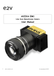
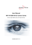
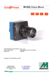
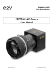
1
DIVIINA® LM1 Line Scan Camera DIVIINA LM1 Camera User Manual 1 1042B -Diviina LM1 11/10 e2v semiconductors SAS 2010 DIVIINA® LM1 Line Scan Camera Summary 1 2 3 CAMERA OVERVIEW ............................................................................4 1.1 1.2 1.3 1.4 1.5 Features ....................................................................................................................................4 Key Specifications ....................................................................................................................4 Description ................................................................................................................................5 Typical Applications ..................................................................................................................5 Models & Part numbers.............................................................................................................5 IMAGE SENSOR .................................................................................6 2.1 2.2 Sensor Structure......................................................................................................................6 Response of the sensors...........................................................................................................6 CAMERA HARDWARE INTERFACE..............................................................7 3.1 3.2 3.3 3.3.1 Mechanical Drawings.................................................................................................................7 Sensor alignment.......................................................................................................................7 Input/output Connectors and LED ...........................................................................................8 Power Connector .................................................................................................................................................................... 8 3.3.2 3.3.3 4 5 6 Camera control connector ................................................................................................................................................... 9 Gigabit Ethernet Connector ............................................................................................................................................... 9 STANDARD CONFORMITY.................................................................... 10 4.1 4.2 4.3 4.4 4.5 CE Conformity .........................................................................................................................10 RoHs Conformity .....................................................................................................................10 GigE Vision Conformity ...........................................................................................................10 GenICam Standard..................................................................................................................10 Standard Features Naming Convention (SFNC) ....................................................................10 GETTING STARTED ........................................................................... 11 5.1 5.2 Out of the box ...........................................................................................................................11 Setting up in the system ...........................................................................................................12 CAMERA SOFTWARE INTERFACE............................................................ 13 6.1 GigE Vision concepts ...............................................................................................................13 6.1.1 6.1.2 6.1.3 6.2 GenICam..................................................................................................................................................................................13 GenICam Standard ...............................................................................................................................................................13 SFNC ........................................................................................................................................................................................13 Getting started with GigE Vision interface...........................................................................13 6.2.1 6.2.2 6.2.3 2 Network setup.......................................................................................................................................................................13 Software installation...........................................................................................................................................................14 Interactive camera control................................................................................................................................................15 1042B -Diviina LM1 11/10 e2v semiconductors SAS 2010 DIVIINA® LM1 Line Scan Camera 6.2.4 6.3 Camera first power on.........................................................................................................................................................18 IP address policy tips .............................................................................................................18 7 More ............................................................................................ 18 8 Camera Commands ............................................................................. 19 8.1 8.2 8.3 Device Information .................................................................................................................19 Image size control ..................................................................................................................21 Acquisition and trigger controls.............................................................................................25 8.3.1 8.3.2 8.4 8.5 8.6 8.7 8.8 9 Camera Trigger synoptics..................................................................................................................................................25 Acquisition and Trigger modes.........................................................................................................................................25 Counters and timers controls .................................................................................................29 Event generation .....................................................................................................................30 Analog controls........................................................................................................................31 GigE vision transport layer .....................................................................................................33 User Sets ................................................................................................................................35 APPENDIX A: Test Patterns ................................................................. 36 9.1 9.2 9.3 1024 Pixels Camera .................................................................................................................36 2048 Pixels Camera.................................................................................................................36 4096 Pixels Camera.................................................................................................................36 10 APPENDIX B: Optical Mounts available ................................................... 37 11 APPENDIX C : LINE TRIGGER MODE .................................................... 39 12 APPENDIX D : Camera Features .......................................................... 43 13 APPENDIX E : TROUBLESHOOTING ..................................................... 45 14 APPENDIX F: Revision History............................................................. 46 10.1 10.2 F-Mount ...................................................................................................................................37 C-Mount ...................................................................................................................................38 3 1042B -Diviina LM1 11/10 e2v semiconductors SAS 2010 DIVIINA® LM1 Line Scan Camera 1 1.1 1.2 CAMERA OVERVIEW Features Sensor: 1024 to 4096 pixels, 10 or 14 µm square Data Rate : 40MPixels on two channels Line Rate Up to 35,5 KHz Bit Depth : 8 bits Gigabit Interface (Base) Dimensions: 60 x 60 x 65 (w, h, l) Anti-blooming Cost effective and easy to use. Fully configurable with GEVPlayer software. Key Specifications Feature/Specification Value Unit Camera Characteristics Resolution pixel size (square) Max line rate 1024 2048 4096 Pixels 10 or 14 10 or 14 10 µm 35.7 18.1 9.5 kHz Bit depth 8 Bits Radiometric Performance at Maximum Pixel Rate and minimum camera gain Typical Max Peak Response (14µm pixel size) 12.5 - LSB/(nJ/cm²) 8bits Peak Response (10µm pixel size) 5.8 - LSB/(nJ/cm²) 8bits Response non linearity 1 2 % PRNU 5 10 % 58 - Dynamic range dB 8bits Functionality (Programmable via Control Interface) Gain Up to 30,8 dB Offset Up to 255 LSB Mechanical and Electrical Interface Size (w x h x l) Weight Lens Mount 4 1042B -Diviina LM1 11/10 60 x 60 x 42 210 g (without mount) mm g M42 x 1 (by default) F (Nikon) or C optional mounts e2v semiconductors SAS 2010 DIVIINA® LM1 Line Scan Camera Sensor alignment Sensor flatness Power supply ±200 µm ±30 µm Single 12 to 24 V 7 (max) W Power dissipation General Features Operating temperature 0 to 65 (front face) °C Storage temperature -40 to 70 °C CE and RoHS compliant, GigEVision 1.1 Regulatory GenICam 1.0 SFNC 1.3 1.3 Description DiViiNA LM1 is a cost efficient CCD line scan camera family with GigE Vision interface. Featuring e2v’s own high performance linear CCD sensors from 1024 pixels up to 4096 pixels, as used in the world recognized AViiVA cameras; DiViiNA LM1 cameras offer high image quality with user-friendly simplicity. DiViiNA LM1 is the perfect candidate for mid range machine vision applications. 1.4 1.5 Typical Applications • Web Inspection (Wood, Paper, Metallurgy) • Part inspection and sorting (Cotton, Rice, Food) • General Machine Vision Inspection Models & Part numbers Table 5-1. Ordering Code Part Number Sensor type (Resolution, Pixels size) Description Camera EV50YLM1GE1010-BA0 1024 pixels, 10µm size DIViiNA LM1 GE 1010 EV50YLM1GE2010-BA0 2048 pixels, 10µm size DIViiNA LM1 GE 2010 EV50YLM1GE4010-BA0 4096 pixels, 10µm size DIViiNA LM1 GE 4010 EV50YLM1GE1014-BA0 1024 pixels, 14µm size DIViiNA LM1 GE 1014 EV50YLM1GE2014-BA0 2048 pixels, 14µm size DIViiNA LM1 GE 2014 Accessories 5 EV50-MOUNT-F F-Mount (Nikon) EV50-MOUNT-C C-Mount 1042B -Diviina LM1 11/10 e2v semiconductors SAS 2010 DIVIINA® LM1 2 IMAGE SENSOR 2.1 Sensor Structure The sensor has a odd/even structure in two taps as following : Note: In GEVPLayer, Odd pixels are equivalent to Tap1 and Even pixels are equivalent to Tap2. 2.2 Response of the sensors 6 1042B -Diviina LM1 11/10 e2v semiconductors SAS 2010 DIVIINA® LM1 3 3.1 CAMERA HARDWARE INTERFACE Mechanical Drawings Reference mounting plane 65 Mechanical reference point 60 52 12 Y= 30±0.05 15 Sensor 60 52 1st pixel 15 Reference mounting plane Reference mounting plane x 4 x M3 thru (refer to the table below) 4 x 2 holes M4 (on the 4 sides) 8mm deep M42 x 1 6 z = 10.18 Optical sensor plane to front face X axis X,Y plan Y axis 3.2 Z axis All dimensions in millimeters Sensor alignment Sensor size (pixels #) x with 14µm sensor (mm) x with 10µm sensor (mm) 7 1042B -Diviina LM1 11/10 1024 20.83 22.88 2048 13.66 17.76 4096 7.52 e2v semiconductors SAS 2010 DIVIINA® LM1 3.3 Input/output Connectors and LED Trigger Connector Green Power on LED Ethernet Connector With its 2 x LEDs Power Connector : Hirose 6pts 12v to 24v 3.3.1 Power Connector Camera connector type: Hirose HR10A-7R-6PB (male) Cable connector type: Hirose HR10A-7P-6S (female) Signal PWR PWR PWR GND GND GND Camera side description 8 1042B -Diviina LM1 11/10 Pin 1 2 3 4 5 6 Power supply from 12v to 24v e2v semiconductors SAS 2010 DIVIINA® LM1 3.3.2 Camera control connector Camera connector type: Cable connector type: Hirose HR10A-7R-5SB Hirose HR10A-7P-5P (male) Signal LVDS IN1+ / TTL IN1 LVDS IN1LVDS IN2+ / TTL IN2 LVDS IN2GND Pin 1 2 3 4 5 1 4 5 2 3 Receptacle viewed from camera back IN1 is connected on Line0 and allows to control external line trigger mode. IN2 is connected on Line1 and allows to control external frame trigger mode. 3.3.3 Gigabit Ethernet Connector Camera connector type: RJ45 8pin female Signal MDI_0+ MDI_0MDI_1+ MDI_2+ MDI_2MDI_1MDI_3+ MDI_3- 9 1042B -Diviina LM1 11/10 Pin 1 2 3 4 5 6 7 8 e2v semiconductors SAS 2010 DIVIINA® LM1 4 STANDARD CONFORMITY The DIVIINA cameras have been tested using the following equipment: ¾ A shielded power supply cable ¾ A Ethernet straight cable cat. 6. e2v recommends using the same configuration to ensure the compliance with the following standards. 4.1 CE Conformity The DIVIINA cameras comply with the requirements of the EMC (European) directive 89/336/CEE (EN 50081-2, EN 61000-6-2). 4.2 RoHs Conformity DIVIINA cameras comply with the requirements of the RoHS directive 4.3 GigE Vision Conformity DIVIINA LM1 cameras comply with the requirement of GigE Vision 1.1 standard. 4.4 GenICam Standard DIVIINA LM1 cameras comply with the requirement of GenICam 1.0 standard. 4.5 Standard Features Naming Convention (SFNC) DIVIINA LM1 cameras comply with the requirement of SFNC 1.3 standard. Warning: Changes or modifications to this unit not expressly approved by the party responsible for compliance could void the user's authority to operate this equipment. 10 1042B -Diviina LM1 11/10 e2v semiconductors SAS 2010 DIVIINA® LM1 5 GETTING STARTED 5.1 Out of the box The contains of the Camera box is the following : There is no CDROM delivered with the Camera : Both User Manual (this document) and GevPlayer control software have to be downloaded from the web site : This ensure you to have an up-todate version. Main Camera page : www.e2v.com/cameras On the appropriate Camera Page (LM1) you’ll find a download link first version of GevPlayer compliant is indicated in the last Chapter GEVEPlayer download requires a login/password : ¾ Login : pleora ¾ Password : vercors 11 1042B -Diviina LM1 11/10 e2v semiconductors SAS 2010 DIVIINA® LM1 5.2 Setting up in the system Vocabulary : w = size of the sensor line (40,96mm for the 4k 10µm) FOV = Field Of View (width of the web inspected by the sensor line) in mm. L = Working distance (from the Lens to the Web) in mm. f = focal distance of the lens in mm. S = Speed of the web in mm/s We have : w FOV = f L The ratio M = w/FOV is called Magnification. w The FOV is grabbed by 4096 pixels in the width. CCD Plan f In order to get a ratio of 1 :1 in your image, at the web speed of S, your line rate has to be set : Focal Plan Line Rate = (S/FOV) x 4096 Ex : if the FOV = 11 cm (110mm) and the speed of the web is S= 0,3 m/s (300mm/s) the line rate will be : Line Rate = (300 /110) x 4096 = 11170 Lines/s. If you use a 60mm lens, the working distance will be : L = (60 x 110) / 40,96 = 161mm. L s FOV This will certainly require a macro lens. 12 1042B -Diviina LM1 11/10 e2v semiconductors SAS 2010 DIVIINA® LM1 6 CAMERA SOFTWARE INTERFACE 6.1 GigE Vision concepts Camera interface is compliant with "Gigabit Ethernet Vision" (GigE Vision) or (GEV). GEV normalizes image transport and camera control communications over usual IP networks. Physical GEV carrier has a bandwidth of one gigabit per second (1Gbit/s). GEV is widely used by camera manufacturers and imaging software suppliers. 6.1.1 GenICam Camera interface is compliant with "Generic Interface for Cameras" (GenICam). GenICam normalizes the camera control interface with software application. The target is to have a single application controlling cameras from any model and brand the same way. It introduces the concept of user manual, not for humans but to software application. Application reads this user manual to control cameras. GenICam has 2 parts, "GenICam Standard" and "GenICam Standard Features Naming Convention" (SFNC) 6.1.2 GenICam Standard It normalizes the camera control rules. It can be considered as the grammar of the user manual. From programmer's point of view, all cameras are controlled with the same way by a single Software Developer’s Kit (SDK). 6.1.3 SFNC From vision point of view, camera feature names are standardized by SFNC. It can be considered as the vocabulary of the user manual. 6.2 Getting started with GigE Vision interface This chapter shows how to connect a GEV camera for the first time. Refer to TBD for more details on GEV interfacing. 6.2.1 Network setup The following is the simplest example of a Gigabit IP network. A single Ethernet cable is connected in RG45 receptacles of GEV camera and PC. Select a "CAT6" shielded twisted pair quality to get a reliable 1Gbit/s. This cable is available at any computer shop. Recent PC have a gigabit RG45 plug on the motherboard. Factory setup has set the camera to the default IP subnet169.254.X.X. The PC interface is set to this default IP subnet as follows: Open the Network interface properties. Settings are shown on Windows XP. 13 1042B -Diviina LM1 11/10 e2v semiconductors SAS 2010 DIVIINA® LM1 Set TCP-IP v4 interface properties to IP address 169.254.0.101 and subnet mask to 255.255.0.0 6.2.2 Software installation A GigE Vision software is required. Use your own or install PureGEV, downloadable from www.e2v.com site. A PureGEV license is included in camera package. Refer to PureGEV installation manual for instructions. The following assumes Pleora's PureGEV is installed. To keep things simple, the firewall should be temporarly turned off. 14 1042B -Diviina LM1 11/10 e2v semiconductors SAS 2010 DIVIINA® LM1 6.2.3 Interactive camera control PureGEV Player is used to control camera interactively and display images. : ¾ Click "Communication Control" button and in "Communication Control" window, set the "AnswerTimeout" feature to 4000 "Select / Connect" button opens the GEV Device Selection window. GigE cameras appears. 15 1042B -Diviina LM1 11/10 e2v semiconductors SAS 2010 DIVIINA® LM1 Click on camera and check "License" value id "Valid" and click OK. In GEV Player window, "Gev Device control" and "Play" are now active. Once connected to the Camera you have an easy access to all its features when you click on “GEV DeviceControl”. The visibility of these features can be associated to three types of users: Beginner, Expert or Guru. Then you can make life easy for simple users. Set Features alphabetically Set Features inside several items 16 1042B -Diviina LM1 11/10 e2v semiconductors SAS 2010 DIVIINA® LM1 Beginner :The number of features with “Beginner ” visibility should be limited to all basics features of the device, and easy to use. Expert : features that require a more in-depth knowledge of the camera functionality. This is the preferred visibility level for all advance features in the camera. Guru : Advanced feature that might bring the camera into a state where it will not work properly anymore if it is set incorrectly for the current mode operation. Click "Play" to start grab. Check camera image on display. 17 1042B -Diviina LM1 11/10 e2v semiconductors SAS 2010 DIVIINA® LM1 6.2.4 Camera first power on At the power on of Diviina LM1 camera, controls are generated inside the camera and images are generated without triggers configuration (like in mode free run for a Camera Link camera). The Acquisition mode is continuous; camera take continuous frame of 100 lines (value by default of Height feature). Each line is acquired in Continuous mode with Exposure time and acquisition line period defined as the minimum Line period of each sensor. 6.3 IP address policy tips Camera IP address is defined by one of the following policies : LLA, DHCP and fixed IP. LLA policy is recommended for dedicated GEV links, as no configuration is required except the default subnet setting in PC Ethernet interface. Default subnet is 169.254.X.X. DHCP policy is recommended when GEV is shared with other Ethernet traffic or when PC/cameras are moved frequently. DHCP can set a dedicated IP address to a given camera. Fixed IP policy is a simple policy, but not recommended, as address consistency is not insured in time. 7 More To get further, refer to the following documents, available from http://www.e2v.com/cameras "iPort PureGEV Quick Start Guide" has more details on network and player. Frequently Asked Questions (FAQ) are available in our knowledge database. Reader's comment and customer request are sent to mailto:[email protected]. Copyright e2v, this paper can be reproduced freely, including this notice. It cannot be sold without written approval. 18 1042B -Diviina LM1 11/10 e2v semiconductors SAS 2010 DIVIINA® LM1 8 Camera Commands 8.1 Device Information These values allow identifying the Camera. They can be accessed through the GEVPlayer software in the “GevDeviceControl” button. Information of the camera are separated in two parts : • At the beginning of the list with the section Device information for the information of the e2v camera • At the end of the list with information relative to the NXT mini All these values are fixed in factory except the Camera User ID which can be fixed by the Customer: • • • 19 DeviceVendorName “e2v” Ö Interface : IString Ö Can not be written Ö Visibility : Beginner DeviceModelName: “DiviinaLM1GE” Ö Interface : IString Ö Can not be written Ö Visibility : Beginner DeviceManufacturerInfo : Part number of the camera ex: “EV50YLM1GE4010-BA0” Ö Interface: IString Ö Can not be written Ö Visibility : Beginner 1042B -Diviina LM1 11/10 e2v semiconductors SAS 2010 DIVIINA® LM1 • DeviceID : serial number of the Camera ex : 0908P0001-AB with : • “09” : Year of manufacturing • “08” : week in the year • “P” as Proto, “M” as Manual, “A” as automatic : type of testing • “0001” : Identification number AB: Fab indice. Ö Interface : IString Ö Can not be written Ö Visibility : Expert • DeviceUserID: Can be set by the Customer to identify his Camera Ö Interface : IString Ö Can be written Ö Visibility : Expert • DeviceScanType: This feature specifies the scan type of the sensor. Ö Interface : IEnumeration Choice : “Linescan” is the factory value Choice : “Areascan” is used when customer wants to trig the frame with the Programmable Logic Controleur (PLC) of the camera. Ö Can be written Ö Visibility : Beginner • DeviceFirmwareVersionMajor : Can be get by the Customer to identify the Major Version of the Firmware Camera. Ö Interface : IString Ö Can not be written Ö Visibility : Beginner • DeviceFirmwareVersionMinor: Can be get by the Customer to identify the Minor Version of the Firmware Camera. Ö Interface : IString Ö Can not be written Ö Visibility : Beginner • DeviceFirmwareVersionSubMinor: Can be get by the Customer to identify the SubMinor Version of the Firmware Camera. Ö Interface : IString Ö Can not be written Ö Visibility : Beginner Note : Some additional information are available at the end of the GEVDeviceControl windows relative to the Pleora IP engine. 20 1042B -Diviina LM1 11/10 e2v semiconductors SAS 2010 DIVIINA® LM1 8.2 Image size control • 21 SensorWidth: Gives the maximum effective width of the sensor. For exemple a 4k sensor has a sensor width of 4096 pixels. Ö Interface : IInteger Ö Unit : pixels Ö Can not be written Ö Visibility : Expert 1042B -Diviina LM1 11/10 e2v semiconductors SAS 2010 DIVIINA® LM1 22 • SensorHeight : gives the maximum effective height of the sensor. A linescan camera has only one line. Ö Interface : IInterger Ö Unit : pixels Ö Can not be written Ö Visibility : Expert • SensorDigitalisationTaps : Gives the number of tap of the camera sensor. LM1 Camera has 2 taps. Ö Interface: IEnumeration Ö Can not be written Ö Visibility : Expert • Width : this feature represents the actual image width expelled by the camera. It can be defined from 1 to the maximal sensor width. Ö Interface: IInteger Ö Unit : pixels Ö Values available: From 1 to SensorWidth Ö Can be written Ö Visibility : Beginner • Height : this feature represents the actual image height expelled by the camera. Ö Interface: IInteger Ö Unit : pixels Ö Values available : From 1 to 16384 Ö Can be written Ö Visibility : Beginner • OffsetX: this feature represents the horizontal offset from the origin of the AOI (Area Of Interest). It can be defined from 1 to the maximal sensor width. Ö Interface: IInteger Ö Unit : pixels Ö Values available: From 1 to SensorWidth Ö Can be written Ö Visibility : Beginner • BinningHorizontal : this feature represents the horizontal photo sensitive cells that must be combined together. A value of one indicates that no horizontal binning is performed by the camera. Ö Interface: IInteger Ö Can not be written Ö Visibility : Expert • DecimationHorizontal: this feature allows horizontal sub-sampling of the image. A value of one indicates that the camera performs no horizontal decimation. Ö Interface: IInteger Ö Can not be written Ö Visibility : Expert • DecimationVertical :this feature allows vertical sub-sampling of the image. A value of one indicates that the camera performs no horizontal decimation. 1042B -Diviina LM1 11/10 e2v semiconductors SAS 2010 DIVIINA® LM1 Ö Interface: IInteger Ö Can not be written Ö Visibility : Expert • PixelFormat: this feature indicates the format of the pixel to use during the acquisition. LM1 camera is a 8 bit camera so the available format is Mono8. Ö Interface : IEnumeration Ö Can not be written Ö Visibility : Beginner • PixelCoding : this feature indicates the coding of the pixel in the image. LM1 camera is a 8 bit camera so the available pixel coding is Mono. Ö Interface : IEnumeration Ö Can not be written Ö Visibility : Expert • PixelSize: this feature indicates the total size in bits of a pixel of the image. LM1 camera has a bit depth of 8 bits. Ö Interface : IEnumeration Ö Can not be written Ö Visibility : Expert • PixelColorFilter : this feature indicates the type of color filter that is applied to the image. LM1 camera is a black and white linescan camera whitout color filter. Ö Interface : IEnumeration Ö Can not be written Ö Visibility : Expert • TestImageSelector : Defines if the data comes from the Sensor or the FPGA (test Pattern). This command is available in “Image Size Control” section of the GEV Device Control : Ö Interface : IEnumeration 23 1042B -Diviina LM1 11/10 e2v semiconductors SAS 2010 Choice “Off” to switch to CCD image sensor Choice “IPEngineTestPattern” to switch to Test Pattern. Ö Can be written Ö Visibility : Expert DIVIINA® LM1 The Test pattern is a single ramp. The test pattern is generated in the FPGA: It’s used to point out any interface problem with the application. The test pattern is a 8bit width pattern composed with several ramps from 0 to 255 all along the whole Camera definition. Then the number of ramps depends on the number of pixels of the Camera Test patterns are detailed in Appendix A. 24 1042B -Diviina LM1 11/10 e2v semiconductors SAS 2010 DIVIINA® LM1 8.3 8.3.1 Acquisition and trigger controls Camera Trigger synoptics External triggers on receptacle pins are feeding PLC line1 and Line2. Q4 and Q5 are driving exposure triggers. Q12 is driving Frame trigger and Q14 is driving acquisition trigger. By convention, Pin1 has the exposure trigger, Pin2 is available for others triggers and data input. 8.3.2 Acquisition and Trigger modes Acquisition, Frame and Line can be triggered by internal or external signals. Genicam camera has 4 real time controls: Line, exposure, frame and acquisition. An acquisition is defined as the capture of a sequence of one or many frames witch is also a capture of one or many lines. For each line an exposure time and an acquisition line period are controlled. Acquisition Frame 1 2 3 4 5 6 7 8 9 10 11 Line and exposure Image output In the Ö Ö Ö Ö Ö Ö Ö example above. We have an acquisition of 2 lines – Frames. Trig 1 is not taken in account because the acquisition was not started. Trig2 is not taken in account because the Frame 1 is not yet valid. Trig3 & 4 are OK for the Frame 1 Trig5 is taken in an additional Frame 1 completed in 1 line because the Frame signal ends. Trig6 is not taken in account because Frame 2 is not yet valid Trig7 & 8 are OK for the Frame 2 Trig9 & 10 are OK for the Frame 3 : The Frame has started before the acquisition ends then the Frame has to be finished. Ö Trig 11 is not taken in account because the Frame and the acquisition are not valid. 25 1042B -Diviina LM1 11/10 e2v semiconductors SAS 2010 DIVIINA® LM1 26 • AcquisitionMode : this feature controls the acquisition mode of the device. Ö Interface : IEnumeration Choice : ”Continuous” : Frames are captured continuous from AcquisitionStart command until AcquisitionStop command. Choice : “Single Frame” to capture one frame Choice : “MultiFrame” the number of frames specified by AcquisitionFrameCount is captured Inside Diviina GigE a memory is available to record either one or many frame, the choice below allow customer to use this feature : Choice : “ContinuousRecording” : record continuously frame Choice : “ContinuousReadout” : gives the frame inside the memory continuously Choice : “SingleFrameRecording” : record one frame. Choice : “SingleFrameReadout” : gives the frame stocked inside memory Ö Can be written Ö Visibility : Beginner • AcquisitionStart: this command starts the acquisition of frame. 1042B -Diviina LM1 11/10 e2v semiconductors SAS 2010 Ö Interface : ICommand Ö Can be written Ö Visibility : Beginner DIVIINA® LM1 • AcquisitionStop: this command stops the acquisition of image(s) at the end of the current frame. Ö Interface : ICommand Ö Can be written Ö Visibility : Beginner • AcquisitionFrameCount : this feature gives the number of frames to be acquired in MultiFrame mode. Ö Interface : IInterger Ö Unit : frame Ö Values available: from 1 to 255 Ö Can be written Ö Visibility : Beginner • LineTriggerMode : this custom feature set pre-defined line acquisition mode. Those modes are the same as those well known of e2v camera link camera. Ö Interface : IEnumeration Choice : ”Continuous” is like “Free Run mode”, Exposure and Line period are set in the camera with features, Exposure and AcquisitionLinePeriod. Choice : “ExtTrigWith ExpTimeSet” : an external trigger starts exposure time and the value of Exposure feature gives the exposition time. Choice : “ExtETCwithOneTrig” : Both exposure time and line period are defined by a Trig signal. Choice : “PlcControlled” gives opportunity to use all Pleora GPIO possibilities available inside Diviina GigE camera. Ö Can be written Ö Visibility : Beginner Line trigger mode is detailed in Appendix C. 27 1042B -Diviina LM1 11/10 e2v semiconductors SAS 2010 DIVIINA® LM1 • ExposureTime : this feature fixes the exposure time when lineTriggerMode selected is Continuous, or ExtTrigWithExpTimeSet(otherwise it’s ignored). Ö Interface : IInteger Ö Unit : Microseconds Ö Values available : From 4 to 65534 Ö Can be written Ö Visibility : Beginner • AcquisitionLinePeriod : this feature fixes the line period when lineTriggerMode selected is Continuous (otherwise it’s ignored). Ö Interface : IInteger Ö The minimum of Line period depends of sensor width : 28µs for the 1K Pixels cameras (35,714kHz) 55µs for the 2K pixels cameras (18,182kHz) 105µs for the 4k pixels cameras (9,523 kHz) Ö The maximum line period is 65535. Ö Unit : Microseconds Ö Can be written Ö Visibility : Beginner The AcquisitionLinePeriod min value is not displayed in GevPlayer for each camera but any attempt to set to a lower value then this will be refused by the camera. In the same way, it’s impossible to set the line period at a lower value than the exposure time. Note that if the exposure time is increased and set at a lower value than the line period, this last one will be automatically adjusted at the value of the exposure time : This modification won’t appear in GevPlayer without disconnect/reconnect 28 1042B -Diviina LM1 11/10 e2v semiconductors SAS 2010 DIVIINA® LM1 8.4 Counters and timers controls All those parameters are allowed to control the 4 timers available inside the camera. Those timers are available when PlcControlled is selected into LineTriggerMode feature. To get further, refer to the following documents, available from http://www.e2v.com. "Programmable Logic Controller, Reference Guide" in section Enhanced Function Block has more details on those parameters. 29 1042B -Diviina LM1 11/10 e2v semiconductors SAS 2010 DIVIINA® LM1 8.5 Event generation This Pleora IPEngine is detailed in the "Programmable Logic Controller, Reference Guide". 30 1042B -Diviina LM1 11/10 e2v semiconductors SAS 2010 DIVIINA® LM1 8.6 31 Analog controls • GainSelector : this feature allows to choice the tap of the sensor where gain is applied : Ö Interface : IEnumeration Choice : “All” to modify in the same time gain of Tap1 and gain of Tap2 of the sensor. Choice : “Tap1” ” to modify only gain ofTap1 (Odd pixels) of the sensor. Choice : ”Tap2” to modify only gain ofTap2 (Even pixels) of the sensor. Ö Can be written Ö Visibility : Beginner • BlackLevelSelector : this feature allows to choice the tap of the sensor where offset is applied : Ö Interface : IEnumeration Choice : “All” to modify in the same time offset of Tap1 and gain of Tap2 of the sensor. Choice : “Tap1” ” to modify only offset ofTap1 of the sensor. Choice : ”Tap2” to modify only offset ofTap2 of the sensor. Ö Can be written Ö Visibility : Beginner • Gain : This feature controls the selected gain as an absolute physical value. Ö Values available from 0 to 880 corresponding to a Gain range of 0 to 31dB (by step of 0,0351dB) Ö Interface : IInteger Ö Unit : None Ö Can be written Ö Visibility : Beginner • BlackLevel : This feature controls the selected analog black level as an absolute physical value. Ö This represents a DC offset applied to the video signal. Ö Interface : IInteger Ö Values available are from 0 to 255 which is equivalent to 16 LSB by steps of 0,063 LSB (8 bits) Ö Unit : LSB Ö Can be written Ö Visibility : Beginner 1042B -Diviina LM1 11/10 e2v semiconductors SAS 2010 DIVIINA® LM1 • AdaptativeTapBalance : This custom feature enables the Adaptative Tap balance. Ö Interface : IBoolean Ö Can be written Ö Visibility : Beginner How works the Adaptative Tap Balance ? The Auto Tap Balance is a Laplace filter which is applied in the FPGA. It automatically solve any odd/even mismatch that can be visible in the image ¾ Whatever the action you may have on the Odd/even Tap Gains to increase the mismatch between the Taps, the filter will correct if enabled ¾ The filter has to be disabled if the inspection is done at Nyquist frequency : Then the tap balance has to be performed by using odd and even Tap Gains. The Camera is delivered with the Adaptative Tap Balance disabled by default. Gains Management and Auto Tap Balance The Selected Gain All is a “virtual” global command which affects both Odd and Even Gains in the same time. Each value set in the Selected Gain All erases Odd and Even Gain values. This gain has to be used when the Auto Tap balance is activated as a “friendly” mode to set quickly the gain level in the Camera without taking care of the Tap balance which is automatically done by the Laplace filter. ¾ The real values of gain applied on each Tap are those set in the odd and even Gain parameters. ¾ Whatever the action you may have on the Odd/even Tap Gains to increase the mismatch between the Taps, the filter will correct if enabled ¾ In CommCam the odd/gains Values are not refreshed after the setting of the Global gain command : You have to refresh them individually with a right click on the value. 32 1042B -Diviina LM1 11/10 e2v semiconductors SAS 2010 DIVIINA® LM1 8.7 GigE vision transport layer All Gigabit Ethernet Vision (GEV) features in this chapter are compliant with GEV version 1.1 and GenICam Standard Feature Naming Convention (SFNC) version 1.3. The 6 main GEV features described here are enough for successful network configuration. Please refer to SFNC document for more features. 33 1042B -Diviina LM1 11/10 e2v semiconductors SAS 2010 34 DIVIINA® LM1 • GevCurrentIPConfigurationDHCP : Controls DHCP search. This setting reduces boot time by 12s. Ö Interface : IBoolean • Choice : “True” only when a local DHCP server will handle camera IP settings. • Choice : “False” ” otherwise. Ö Can be written Ö Visibility : Beginner • GevCurrentIPConfigurationPersistentIP: Disables hard IP address setting. Camera is automatically set in default IP address subnet : 169.254.X.Y. This setting insures IP subnet consistency, prevents IP address conflicts and prevents camera discovery failure. Ö Interface : IBoolean Choice : “True” to enable Persistent IP Choice : “False” ” otherwise. Ö Can be written Ö Visibility : Beginner • GevSCDA: Defines the destination IP address of image stream. Default is the control PC address. Adjusts address when grabbing PC is separated from the control. Multicast and broadcast address ranges are available for distributed machine vision Ö Interface : IInteger Ö Can be written Ö Visibility : Guru • GevSCPHostPort: Destination Port of image stream. Adjusted to fit the grabbing PC port. Ö Interface : IInteger Ö Can be written Ö Visibility : Guru 1042B -Diviina LM1 11/10 e2v semiconductors SAS 2010 DIVIINA® LM1 8.8 User Sets The settings of the Camera can be saved in one User bank. The Factory default settings can be load from its dedicated memory bank. • • • UserSetSelector: This feature give choice of witch memory is selected. Ö Interface : IEnumeration Choice “Default” : selected for load the factory settings Choice”UserSet1” : selected for save and load customer settings Ö Can be written Ö Visibility : Beginner UserSetLoad : Load the User Set specified by “UserSetSelector” to the device and makes it active. Ö Interface : ICommand Ö Can be written Ö Visibility : Beginner UserSetSave : Save the User Set when UserSet1 is specified by “UserSetSelector” to the device. Ö Interface : ICommmand Ö Can be written Ö Visibility : Beginner A synthesis of all camera features is available on APPENDIX D. 35 1042B -Diviina LM1 11/10 e2v semiconductors SAS 2010 DIVIINA® LM1 9 APPENDIX A: Test Patterns 9.1 1024 Pixels Camera The test pattern is composed of 4 successive ramps from 0 to 255 LSB gray values : 9.2 2048 Pixels Camera The test pattern is composed of 8 successive ramps from 0 to 255 LSB gray values : 9.3 4096 Pixels Camera The test pattern is composed of 16 successive ramps from 0 to 255 LSB gray values : 36 1042B -Diviina LM1 11/10 e2v semiconductors SAS 2010 DIVIINA® LM1 10 10.1 APPENDIX B: Optical Mounts available F-Mount F Mount: (Part number EV50-MOUNT-F) Drawing for the additional part (except Nikon BR3) : 37 1042B -Diviina LM1 11/10 e2v semiconductors SAS 2010 DIVIINA® LM1 10.2 C-Mount C Mount : (Part number EV50-MOUNT-C) 38 1042B -Diviina LM1 11/10 e2v semiconductors SAS 2010 DIVIINA® LM1 11 APPENDIX C : LINE TRIGGER MODE This Appendix describes the custom feature of LM1 : LineTriggerMode. Feature allows to easier and quicker control camera. The 3 choices of feature are explained below, if you need more information about these, a FAQ on each mode is available with downloadable file from www.e2v.com site. Timing Specifications This table is for all the synchronization modes. Label • Description Value Td Q4 rising to integration period start delay 350ns Tdr Integration period stop to readout 1,8µs Th Q4 hold time (pulse high duration) 1,1µs td1 Q4/Q5 falling/rising to integration period start delay 350ns td2 Q4/Q5 rising to integration period stop delay 1,3µs Continuous This mode doesn’t require an external trigger. In this case, the line period can be defined in the Camera (see below) but the real line period of the camera depends also on the exposure time set: ¾ If ExposureTime > AcquisitionLinePeriod, the line period is equal to ExposureTime LINE PERIOD LINE PERIOD EXPOSURE N EXPOSURE N+1 READOUT N-1 READOUT N ExposureTime = AcquisitionLinePeriod tdr 39 1042B -Diviina LM1 11/10 e2v semiconductors SAS 2010 DIVIINA® LM1 ¾ If AcquisitionLinePeriod > ExposureTime, the line period is equal to Acquisition Line Period AcquisitionLinePeriod LINE PERIOD LINE PERIOD ExposureTime EXPOSURE N EXPOSURE N+1 READOUT N-1 READOUT N tdr • Ext Trig with integration time set in the camera This mode requires an external trigger ( via Q4) but the exposure time is the one defined in the Camera. td th Exposure Time Q4 Acquisition Line Period EXPOSURE N+1 EXPOSURE N READOUT N-1 READOUT N tdr If the line period of the Trig signal provided to the camera is smaller than the exposure time set in the camera, the “short trig pulses” will be ignored: The exposure set in the camera defines the minimum line period possible. ¾ Q4 is based on an external trigger, if trigger used is not completely the same as Q4 described above, the PLC allows to modify it in order to match input signal and Q4 signal needed. ¾ • 40 Ext Trig with Exposure Time Controlled (ETC) with one Trig 1042B -Diviina LM1 11/10 e2v semiconductors SAS 2010 DIVIINA® LM1 This mode requires an external trigger ( via Q4). Both exposure time and line period are defined by this Trig signal: ¾ The exposure time during the low level of the Trig Signal ¾ The line period between two rising edges of the Trig Signal td1 td2 Acquisition Line Period Q4 Exposure time EXPOSURE N EXPOSURE N+1 READOUT N-1 READOUT N tdr ¾ Q4 is based on an external trigger, if trigger used is not completely the same as Q4 described above, the PLC allows to modify it in order to match input signal and Q4 signal needed. PLC controlled • This mode requires two external triggers ( via Q4 and Q5): ¾ Q5 controls the starting of the exposure time ¾ Q4 controls the end of the exposure time. The line period is defined by the one of the Q5 Trig signal. td1 td2 Q5 Acquisition Lin Period Q4 Exposure Time EXPOSURE N EXPOSURE N+1 READOUT N-1 READOUT N tdr 41 1042B -Diviina LM1 11/10 e2v semiconductors SAS 2010 DIVIINA® LM1 Programmable Logic Controller (PLC) management Signals available at Q4 and Q5 of the PLC have to be as signals described above. To transform trigger like this, a PLC is available between trigger input and Q4 and Q5. ¾ At First power on, PLC is like a “wire” were input and Q4 are directly linked without any signal treatment inside PLC. ¾ Diviina camera has only 2 inputs: one for line trigger and the other for frame trigger; if the PlcControlled mode is used, a new signal has to be created from the line trigger input with PLC help. For more information please refer to the Pleora documentation: “Programmable Logic Controller, Reference Guide”. 42 1042B -Diviina LM1 11/10 e2v semiconductors SAS 2010 DIVIINA® LM1 12 APPENDIX D : Camera Features Feature name AcquisitionFrameCount AcquisitionLinePeriod R/W R/W AcquisitionMode R/W AcquisitionStart AcquisitionStop AdaptativeTapBalance W W R/W BinningHorizontal BlackLevel BlackLevelSelector RO R/W R/W DecimationHorizontal DecimationVertical DeviceFirmwareVersionMajor DeviceFirmwareVersionMinor DeviceFirmwareVersionSubMinor DeviceID DeviceManufacturerInfo DeviceModelName DeviceScanType RO RO RO RO RO RO RO RO R/W DeviceUserID DeviceVendorName ExposureTime Gain Gainselector W RO R/W R/W R/W Height LineTriggerMode R/W R/W OffsetX R/W PixelCoding PixelColorFilter PixelFormat 43 access 1042B -Diviina LM1 11/10 RO RO RO Value From 1 to 255 From minimum sensor value to 65535 Continuous SingleFrame MultiFrame ContinuousRecording ContinuousReadout SingleFrameRecording SingleFrameReadout Enable Disable 1 From 0 to 255 All Tap1 Tap2 1 1 1 0 0 DiviinaLM1 Linescan Areascan e2v From 4 to 65535 From 0 to 880 All Tap1 Tap2 From 1 to 16384 Continuous ExtTrigWithExpTimeSet ExtETCwithOneTrig PlcControlled From 1 to maximum sensor size Mono None Mono8 Interface IInteger IInteger IEnumeration ICommand ICommand IBoolean IInteger IInteger IEnumeration IInteger IInteger IString IString IString IString IString IString IString IString IString IInteger IInterger IEnumeration IInteger IEnumeration IInteger IEnumeration IEnumeration IEnumeration e2v semiconductors SAS 2010 PixelSize SensorDigitalisationTaps SensorHeight SensorWidth 44 RO RO RO RO TestImageSelector R/W UserSetLoad UserSetSave UserSetSelector W W R/W Width R/W 1042B -Diviina LM1 11/10 Bpp8 Two 1 Maximum size of the sensor Off IPEngineTestPattern Default UserSet1 From 1 to maximum pixel size DIVIINA® LM1 IEnumeration IEnumeration IInteger IInteger IEnumeration ICommand ICommand IEnumeration IInteger e2v semiconductors SAS 2010 DIVIINA® LM1 13 APPENDIX E : TROUBLESHOOTING Camera Power up 3s LED Color No LED If GEV Player connection possible : then the LED is HS, else : Check power supply And its characteristics Contact Hotline for RMA 45 1042B -Diviina LM1 11/10 Fixed Green Camera ready e2v semiconductors SAS 2010 DIVIINA® LM1 14 APPENDIX F: Revision History Doc. Revision Preliminary A B C 46 1042B -Diviina LM1 11/10 Comments / Details Camera Ref Preliminary release First Release Mount Drawing Correction “Out of the Box” chapter Firmware 1.0.0 Firmware 1.1.0 Firmware 5.0.0 Firmware 5.0.0 e2v semiconductors SAS 2010 DIVIINA® LM1 A AcquisitionFrameCount, 26 AcquisitionLinePeriod, 27 AcquisitionMode, 25 AcquisitionStart, 26 AcquisitionStop, 26 AdaptativeTapBalance, 31 H Height, 21 L LineTriggerMode, 26 O B BinningHorizontal, 21 BlackLevel, 30 BlackLevelSelector, 30 OffsetX, 21 P D DecimationHorizontal, 21 DecimationVertical, 22 Device Manufacturer info, 18 DeviceFirmwareVersionMajor, 19 DeviceFirmwareVersionMinor, 19 DeviceFirmwareVersionSubMinor, 19 DeviceID, 19 DeviceManufacturerInfo, 18 DeviceModelName, 18 DeviceScanType, 19 DeviceUserID, 19 DeviceVendorName, 18 E ExposureTime, 27 PixelCoding, 22 PixelColorFilter, 22 PixelFormat, 22 PixelSize, 22 S SensorDigitalisationTaps, 21 SensorHeight, 21 SensorWidth, 20 T TestImageSelector, 22 U UserSetLoad, 34 UserSetSave, 34 UserSetSelector, 34 W G Gain, 30 Gainselector, 30 47 1042B -Diviina LM1 11/10 Width, 21 e2v semiconductors SAS 2010 DIVIINA® LM1 How to reach us Home page: www.e2v.com Sales Office: Europe Regional sales office Americas e2v ltd e2v inc 106 Waterhouse Lane 520 White Plains Road Chelmsford Essex CM1 2QU Suite 450 Tarrytown, NY 10591 England USA Tel: +44 (0)1245 493493 Tel: +1 (914) 592 6050 or 1-800-342-5338, Fax: +44 (0)1245 492492 Fax: +1 (914) 592-5148 mailto: [email protected] mailto: [email protected] e2v sas 16 Burospace Asia Pacific e2v ltd F-91572 Bièvres Cedex 11/F., France Onfem Tower, Tel: +33 (0) 16019 5500 29 Wyndham Street, Fax: +33 (0) 16019 5529 Central, Hong Kong mailto: [email protected] Tel: +852 3679 364 8/9 Fax: +852 3583 1084 mailto: [email protected] e2v gmbh Industriestraße 29 82194 Gröbenzell Product Contact: Germany e2v Tel: +49 (0) 8142 41057-0 Avenue de Rochepleine Fax: +49 (0) 8142 284547 BP 123 - 38521 Saint-Egrève Cedex mailto: [email protected] France Tel: +33 (0)4 76 58 30 00 Hotline: mailto: [email protected] 48 1042B -Diviina LM1 11/10 e2v semiconductors SAS 2010