1
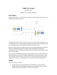
The speed of the motor is measured in revolutions (or rounds) per second (rps).
To determine the motor speed, we can use the shaft encoder. The encoder uses infra
red emitters and detectors that are placed fairly close to each other (about
half an inch or less). When there is a direct line of sight between them the detector is
“on”’ and produces a voltage (normally around 1 to 3 volts). When the line of sight is
blocked the detector doesn’t pick up any infra red light so is “off”, producing 0 volts.
Now, carefully examine the motor and shaft encoder on the AVR Microcontroller Board.
Can you identify the emitter and the detector? The emitter is active high and the detector
is active low (It will go low when it can see the signal).
Power up the AVR Microcontroller Board as from last lab, wire up the POT to the MOT
using the patch cables provided. As you turn the POT, the motor spins at different
speeds.
As you have already noticed, there are 4 holes on the motor, the combination of the
motor and shaft encoder enables you to measure the frequency of the motor by counting
the number of the holes the shaft encoder detects and dividing the number by 4.
4. Tasks
4.1
Task 1
Write an assembly program that receives a character typed in from the keypad and
prints it on the LCD. When the first line is full, the display goes to the next line. When the
two lines are all full, the display is cleared and ready to display a new set of characters.
Assemble your program using AVR Studio, and run it on the AVR Microcontroller Board.
Demonstrate your working program to the Laboratory assessor.
Check Point A:
Signature:
2